Foundation Design using SAFE
Aim: To model a isolated footing do analyse and design to it.
Software that i used---Safe
Step by step procedure
Open safe software
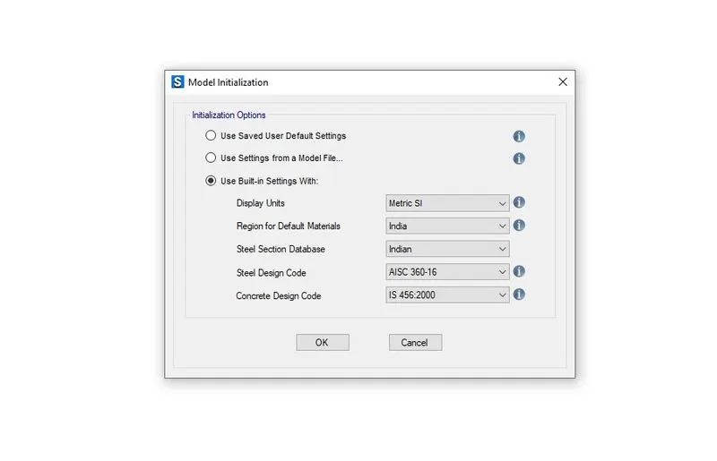
set the initial setting like this
diisplay units- metric
region for material -india
steel section database-Indian
concrete design code-Is 456-2000
set the grid data.
X-axis-2nos-3.2 spacing
y -axis -2nos-3.2 spacing
go to define tab
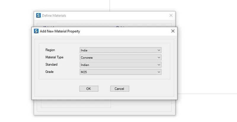
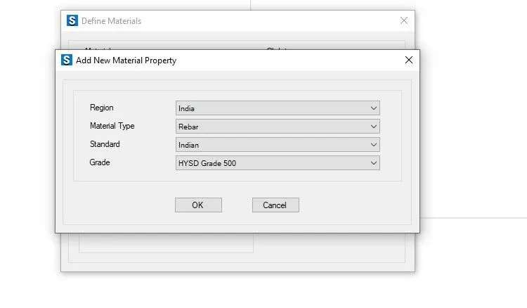
add new material property
concrete-M25
rebar-FE500
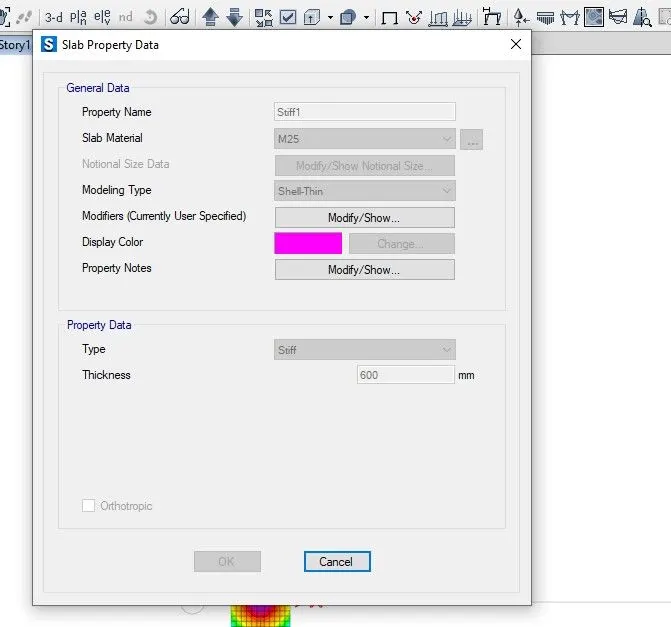
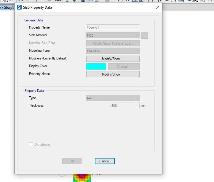
add section property
go to slab section
add new properties
footing slab-mat-600mm thickness -material property-M25.
column -stiff-600 mm thickness-material property-M25.
go to define-spring properties-area spring-add new property
specify the subgrade modulus (compression only)--9000kn/m/m2
subgrade modulus--(factor of ultimate*safe bearing capacity)/maximum settlement
for footing--25
for mat--50
combined-25 mm
subgrade modulus--(3*150)/0.05
-9000 kn/m/m2
now its time for modelling
take draw rectangular slab---set the section property-footing slab
draw the footing slab.
draw point on draw tab
place at the centre of the slab.
take draw area around point tool.
set the shape as rectangular.with dimension 400x400.
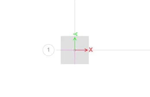
assign
select footing slab.
assign tab---shell---Area spring---select slab1 and assign it to footing slab.
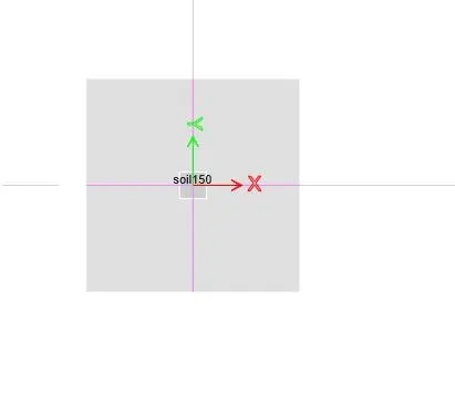
select column joint
assign tab-joint loads-point load.
dead load-666.65 kn
live load-666.65 kn(add to the previous load)
go to design tab
select slab design
set the view preference as per project details.
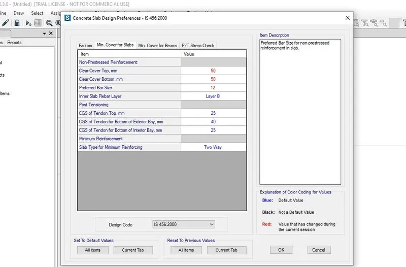
click view flexural design--set is FE 500.
go to define tab
load combination
set service load combination----1dead+1live load
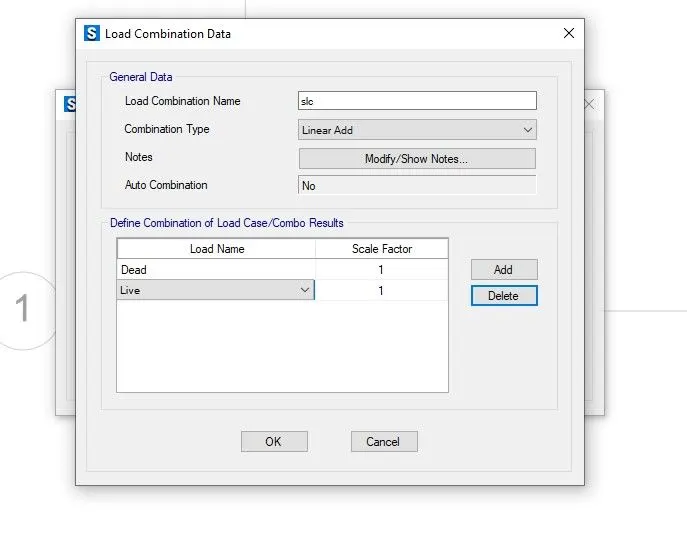
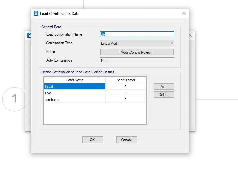
set ulimate load combination---1.5dead+1.5live load
go to design tab
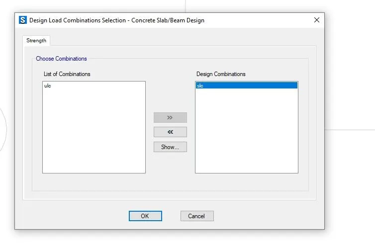
select two load combination into consider for design.
run analysis
go to display tab
click undeformed shape
view combo service
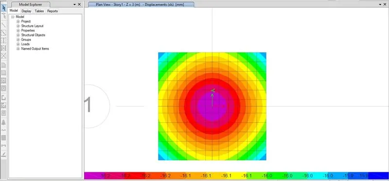
view load-dead
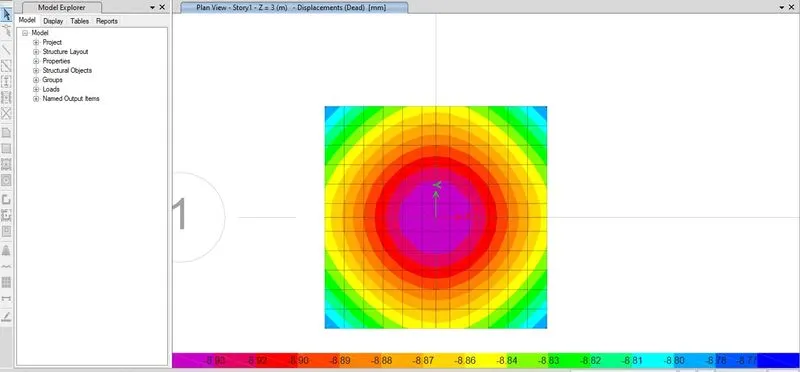
click force /stress diagram
click soil pressure
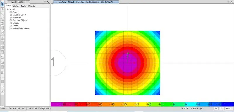
it should below 150
my model get 146
puching shear stress-0.761
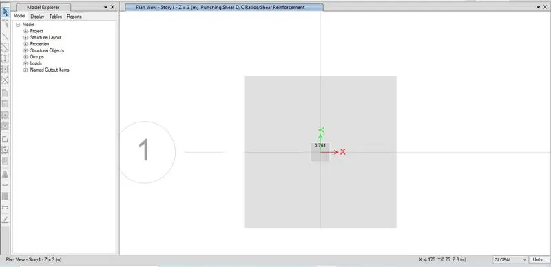
i added strip to the model and design slab.
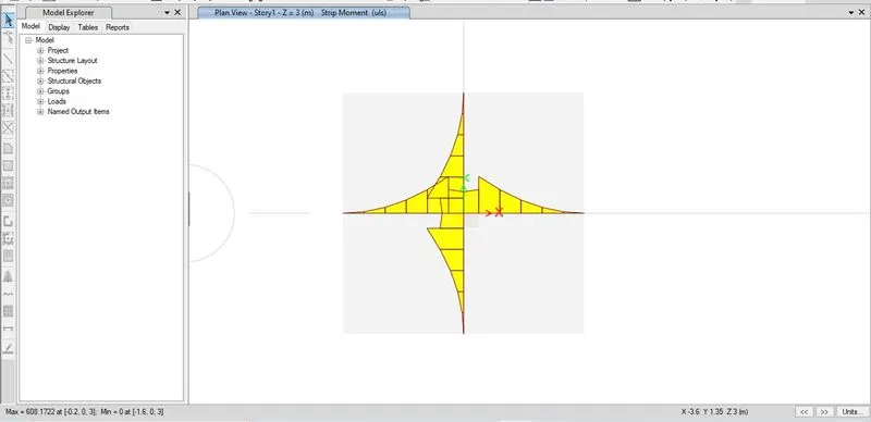
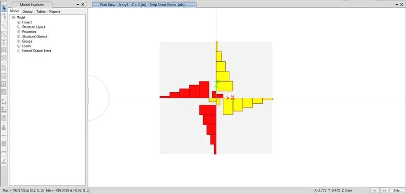
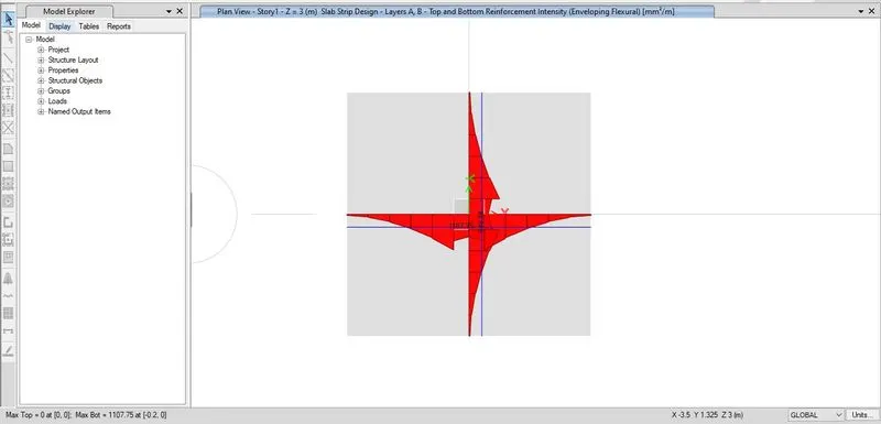
after taking flexural reinforrcement you need provide detailed footing sketch using auto cad
Result: i have modelled a isolated footing done analyse and design to it.
2.Aim: To model a pile foundation do analysis and design to it.
Software that i used---Safe
calucation part
unfactored load-1175kn
dead load-587.5 kn
live load-587.5 kn (split)
pile capacity each-200 kn/mm2
no of required-(1175*1.1)/200
-6.5
take no of pile-8
placed in symmetrical
centre to centre pile-2.5x d
2.5*500
1250
spacing at egdes-500.
Step by step procedure
Open safe software
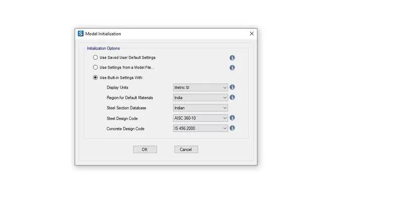
set the initial setting like this
diisplay units- metric
region for material -india
steel section database-Indian
concrete design code-Is 456-2000
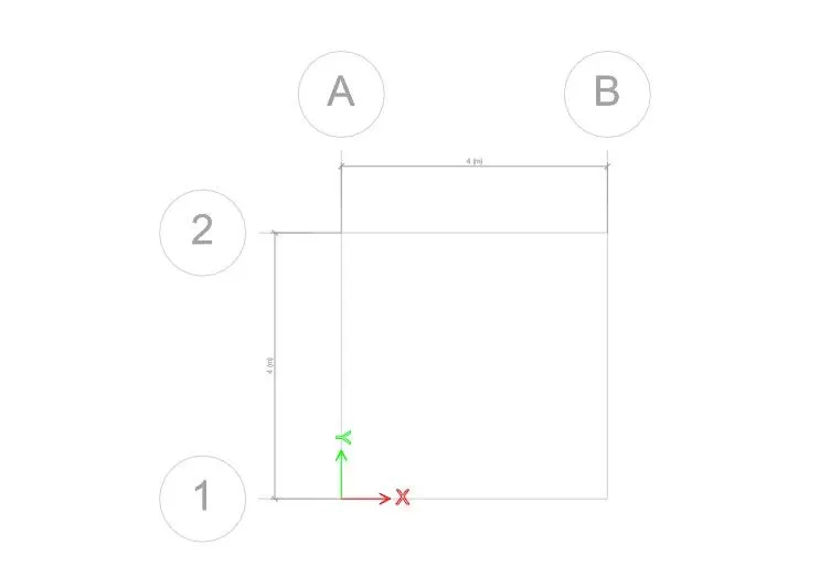
set the grid data.
X-axis-2nos-4 spacing
y -axis -2nos-4 spacing
go to define tab
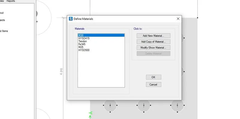
add new material property
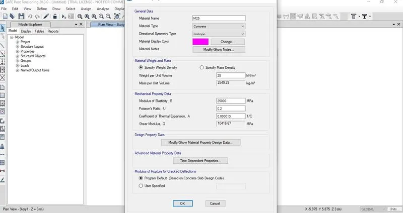
concrete-M25
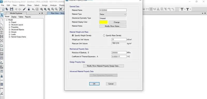
rebar-FE500
add section property
go to slab section
add new properties
footing slab-mat-800mm thickness -material property-M25.
column -stiff-800 mm thickness-material property-M25.
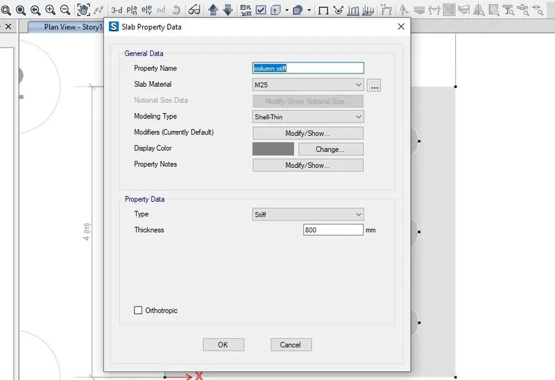
pile -mat -800 mm thickness-material property-M25.
go to define-spring properties-point spring-add new property
specify the translation Z (compression only)--306796kn/m
point spring of pile----EA/l
(25000*(3.14*0.25*500^2))/16000
-306.796kn/mm
-306796kn/m.
now its time for modelling
take draw rectangular slab---set the section property-footing slab
draw the footing slab.
take draw point on draw tab
specify points (750,750),(1250,0),(1250,0) repeat this 2 times above
take draw area around point tool.
select the section property-pile
set the shape as circular.with dimension 500.
for the middle point
select the section property as column stiff.
assign
select footing slab.
assign tab---joint---point spring---select a pile and assign it to all piles.
select column joint
assign tab-joint loads-point load.
dead load-587.5 kn
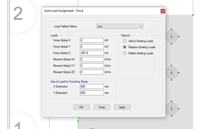
live load-587.5 kn(add to the previous load)
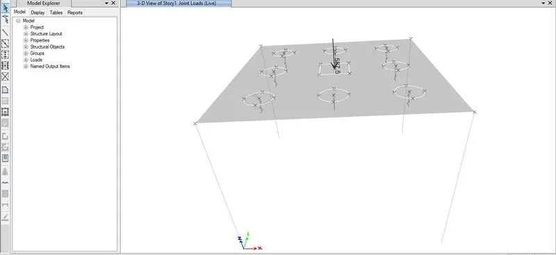
go to design tab
select slab design
set the view preference as per project details.
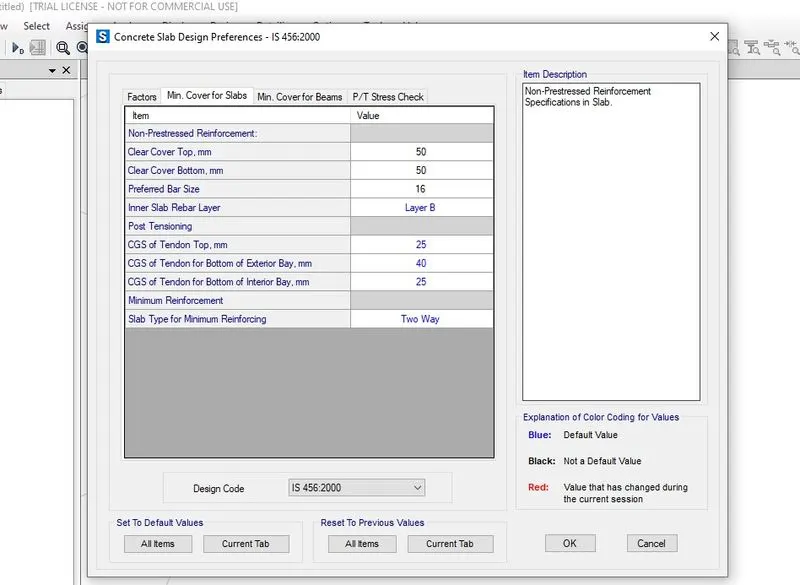
click view flexural design--set is FE 500.
go to define tab
load combination
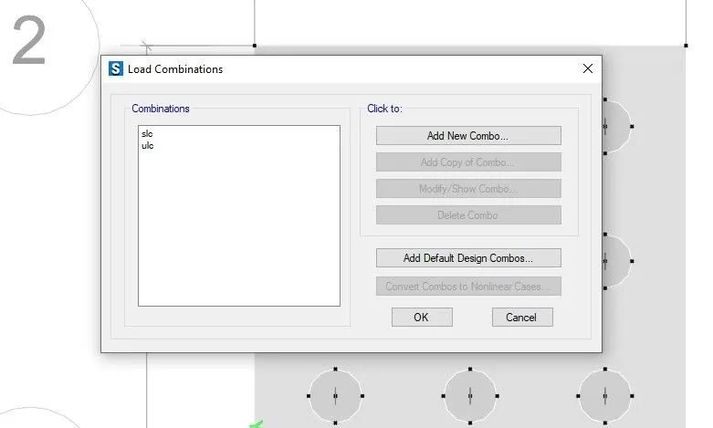
set service load combination----1dead+1live load
set ulimate load combination---1.5dead+1.5live load
go to design tab
select two load combination into consider for design.
run analysis
go to display tab
click undeformed shape
view combo service
click force /stress diagram
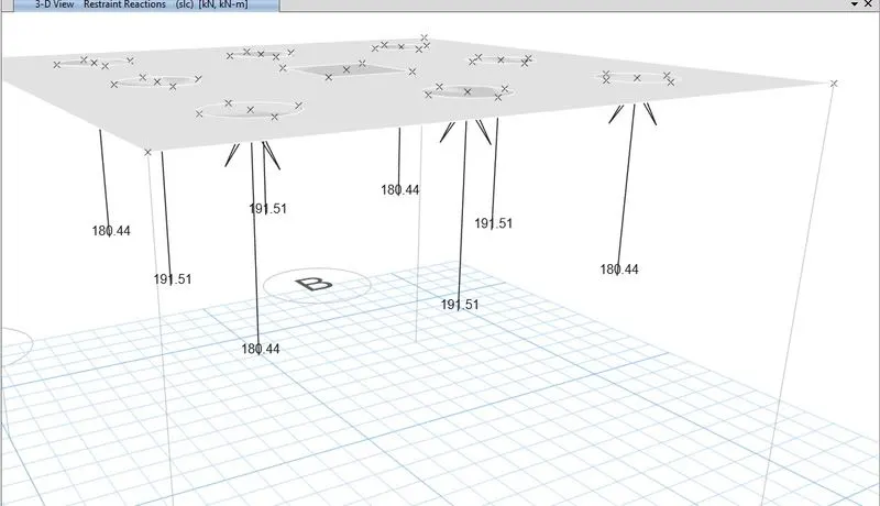
click sping reaction for combo-service
each pile should be less than 200 kn.
because maximum load it can be bear is 200kn.
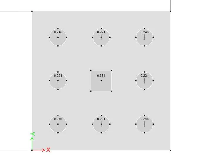
punching shear value is less than 1.
i added strip to the model and design slab.
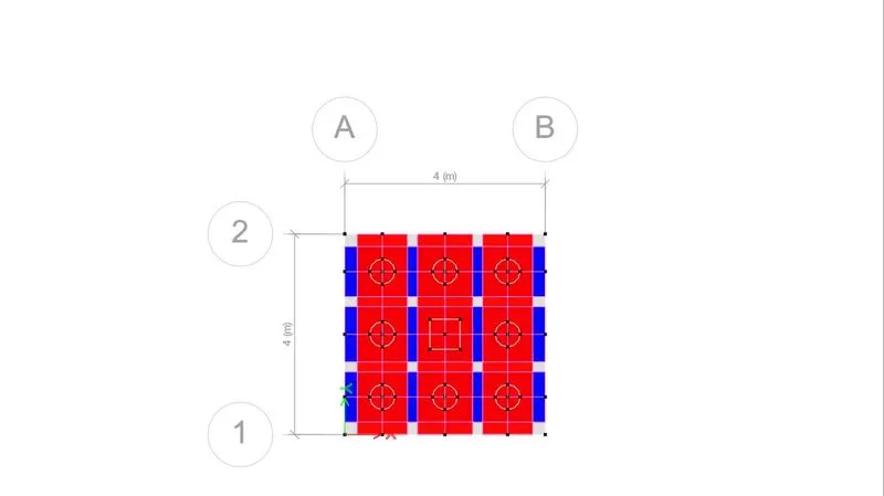
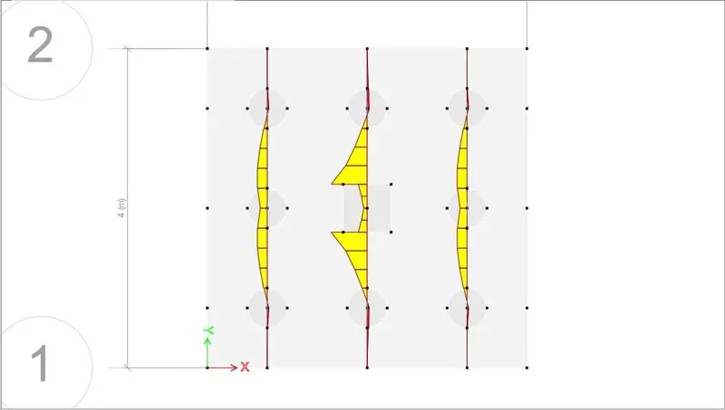
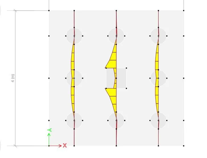
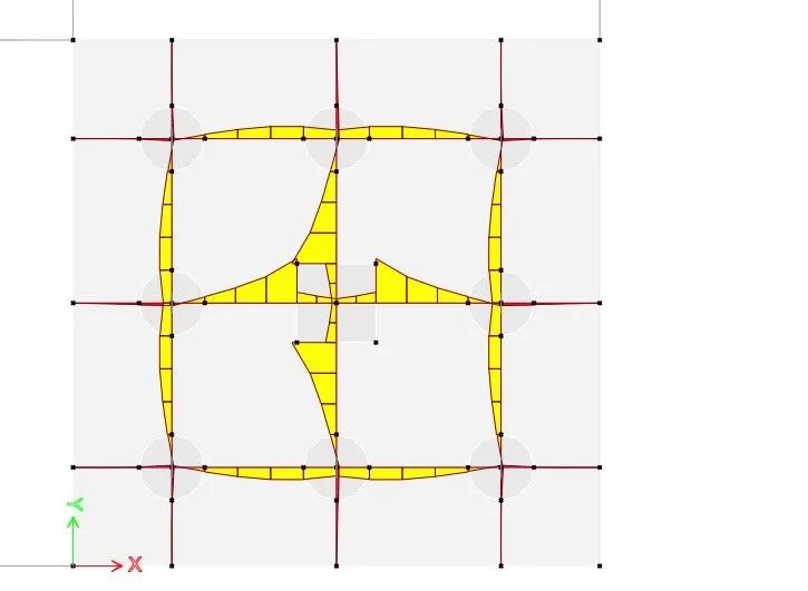
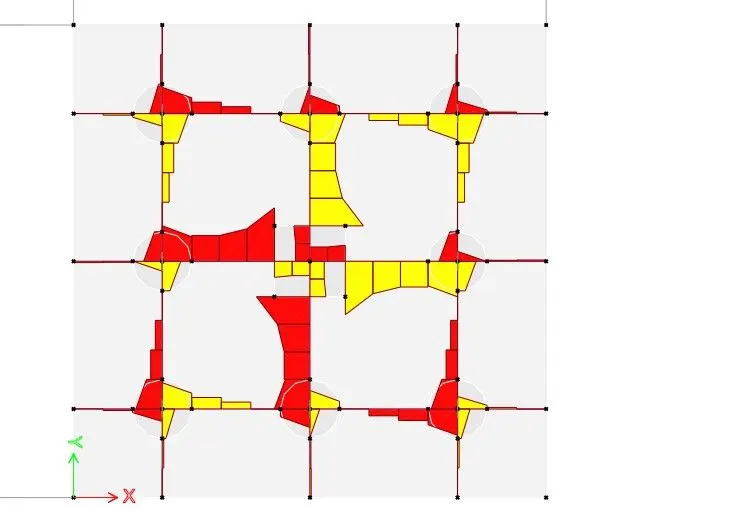
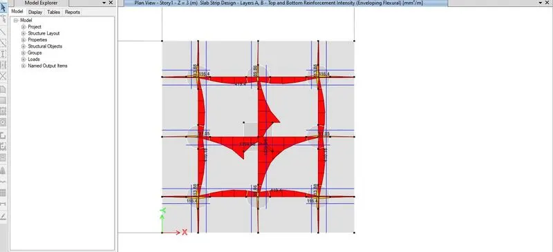
after taking flexural reinforrcement you need provide detailed pile footing sketch using auto cad
Result: i have modelled a pile footing done analyse and design to it.