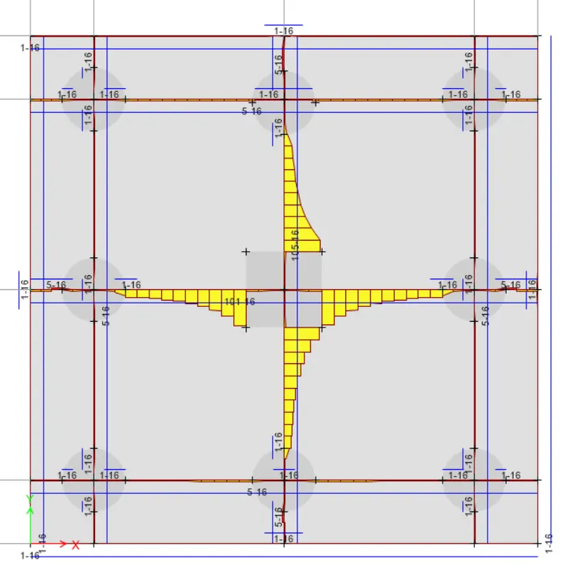
Foundation Design using SAFE
Q1]
AIM: -
Model the isolated footing provided in week 11 challenge on SAFE.
Analyze and design it to verify the size, depth and steel provided as per calculations.
PROCEDURE: -
GIVEN DATA
Column size- 400x400mm
Soil bearing capacity = 150KN/m2
Footing Size= 3.2*3.2m
Grade of concrete= M25
Let’s assume thickness of footing is 600mm
Soil subgrade modulus = (Soil bearing capacity x FOS) / Settlement
= (150x3)/0.05
= 9000 KN/m3
Factored Load = 1.5(D.L.+L.L) = 2000kN
Unfactored load = (2000/1.5) = 1333.33 kN
Dead load = (1333.33/2) = 666.7 kN
Live load = (1333.33/2) = 666.7 kN
Open the SAFE Application and select New Model
Model Initialization dialogue box opens
Display Units: Metric SI
Concrete Design Code: IS 456-2000
steel design code: BS-5950
Press O.K.
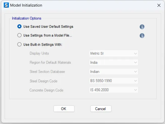
Press O.K.
New Model Quick template dialogue box opens
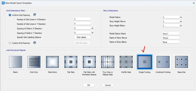
Select Single Footing option
Structural Geometry and properties for Single Footing dialogue box opens
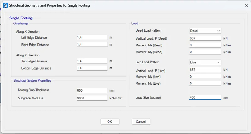
Enter the required data
press O.K.
Click on DESIGN TAB
Click on concrete slab/Beam Design
Select View/Revise Preferences option
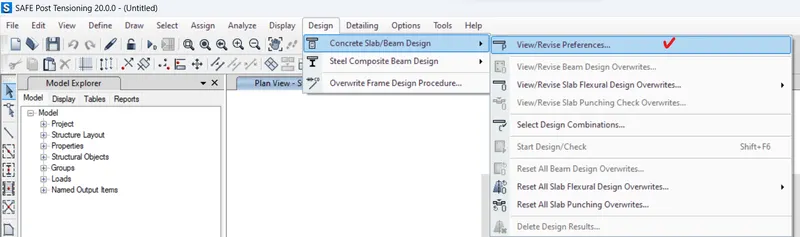
Concrete design Preferences dialogue box opens
Change the required data
Press O.K.
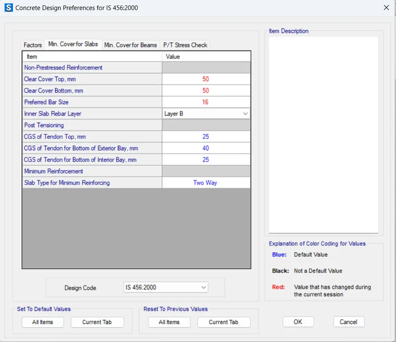
Click on the Define Tab
Select Material Properties
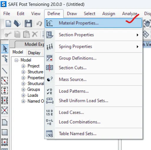
Define Materials dialogue box opens
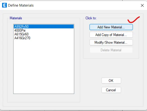
Click on Add New Material
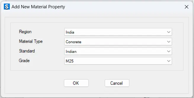
Add New Material Property dialogue box opens
Region: India
Material Type: Concrete
Standard: Indian
Grade: M25
After entering the data, press OK
Click on Add New Material
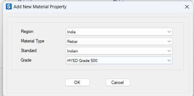
Add New Material Property dialogue box opens
Region: India
Material Type: Rebar
Standard: Indian
Grade: HYSD Grade 500
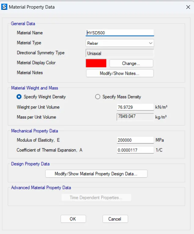
After entering the data, press OK
Click on the Define Tab
Click on Section Properties and select Slab Sections
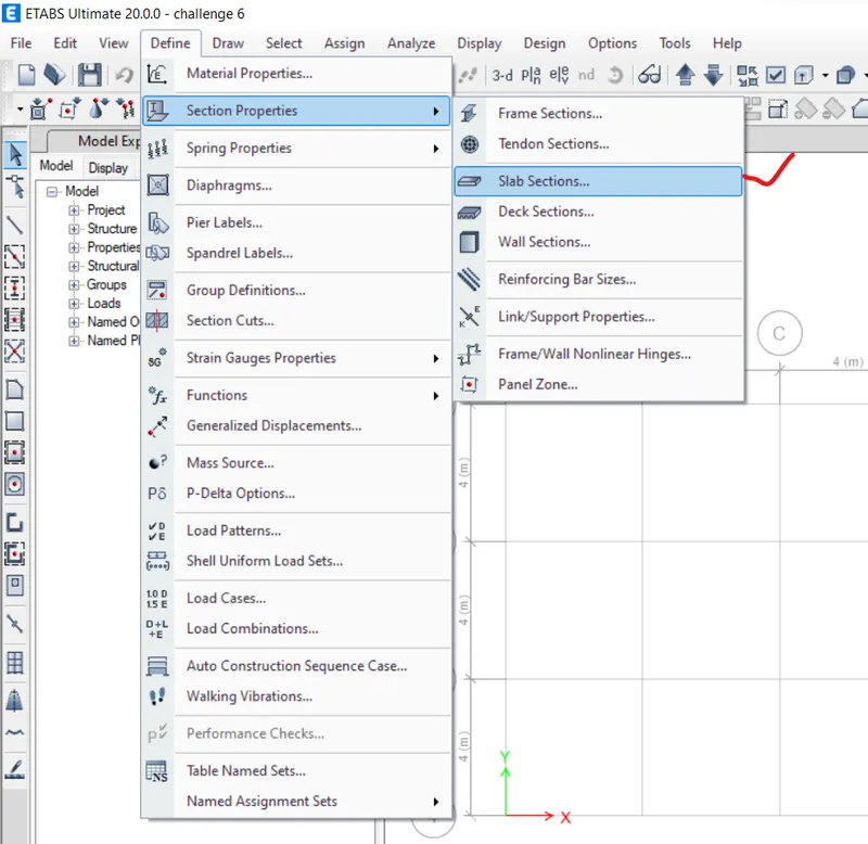
Slab Properties dialogue box opens
Click on Add New Property
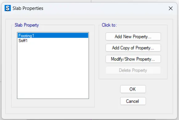
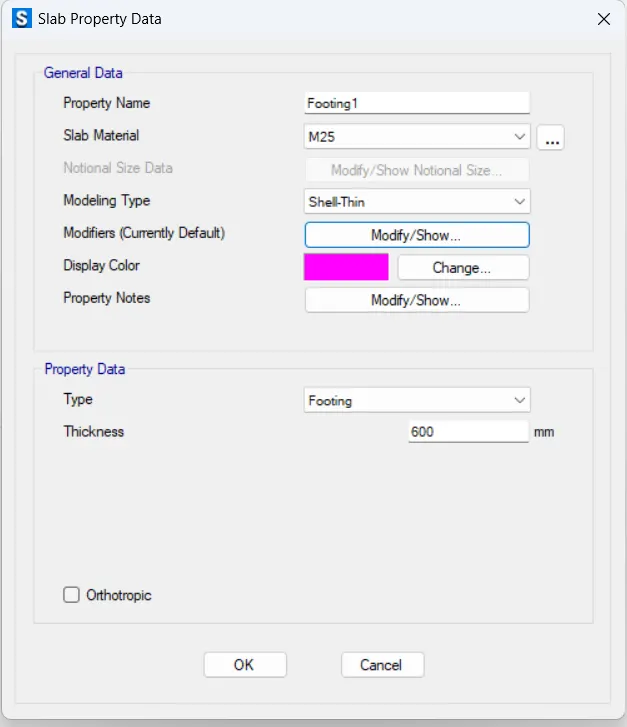
Slab property Data dialogue box opens
Propert name: footing1
Slab material: M25
Type: footing
Thickness: 600mm
Press O.K
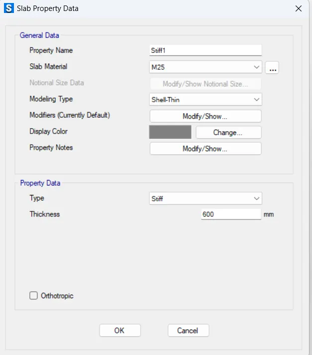
Click on Add New Property
Slab property Data dialogue box opens
Propert name: Stiff1
Slab material: M25
Type: Stiff
Thickness: 600mm
Press O.K
Click on the Define Tab
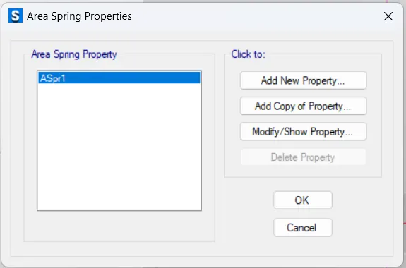
Click on Spring Properties and select Area Springs
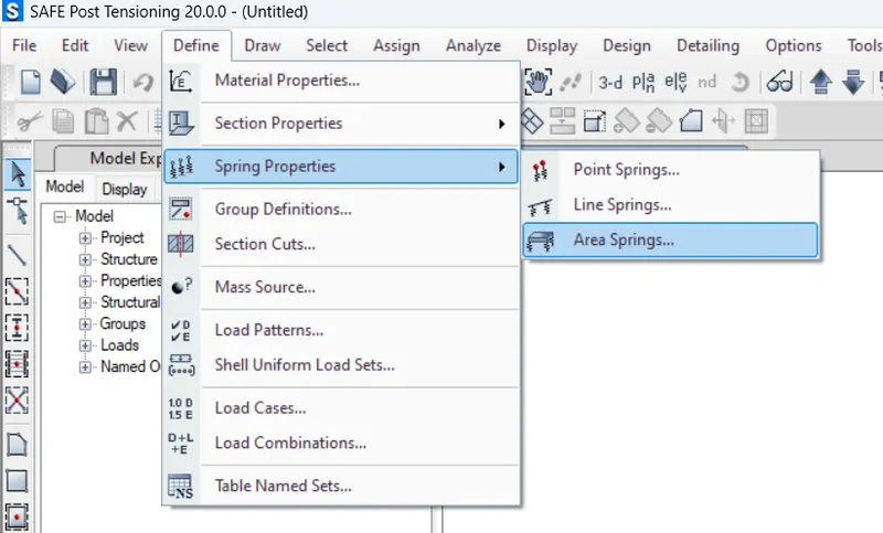
Area Spring Property dialogue box opens
Click on Add New Property
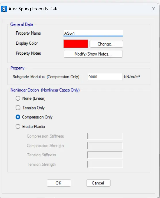
Area Spring Property Data dialogue box opens
Subgrade modulus: 9000kN/m3
Press OK
Select the Footing
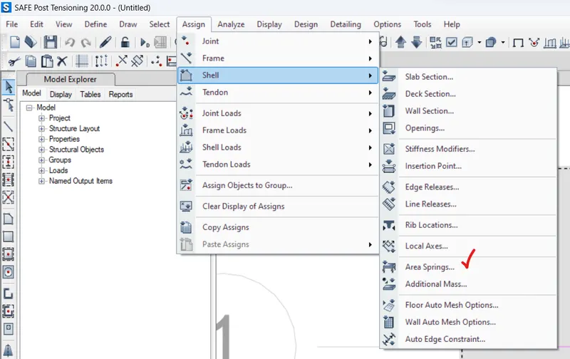
Click on ASSIGN TAB
Click on Shell
Select Area Springs
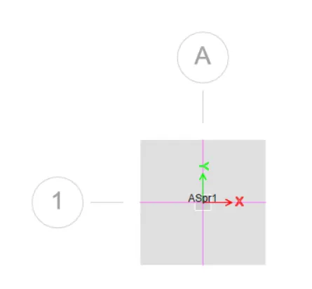
We assigned the Subgrade modulus to the Model.
Check whether loads are assigned.
Click on DISPLAY TAB
Click on Show Load Assign
Select Joint
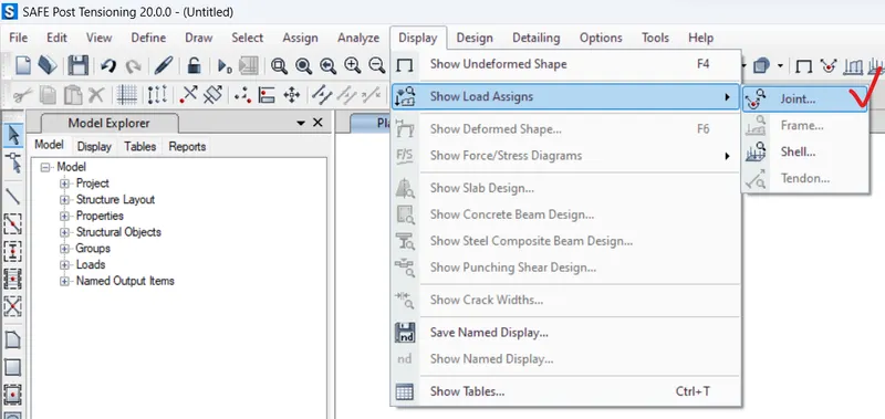
Show Joint Loads dialogue box opens
Load pattern: dead
Load Type: forces
Click on Apply
Press OK
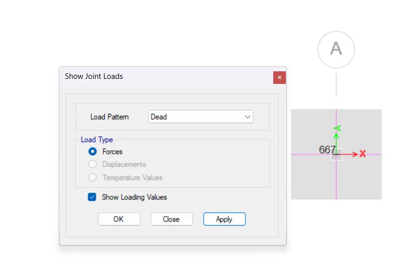
We can see than 667kN point load is applied.
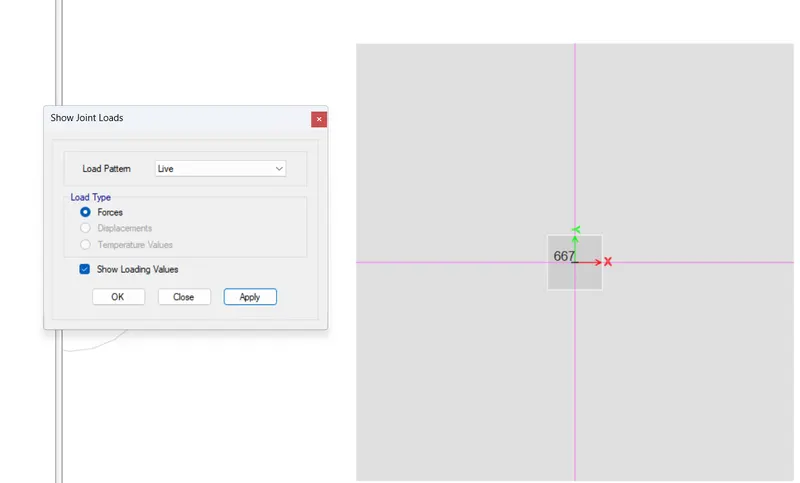
Show Joint Loads dialogue box opens
Load pattern: dead
Load Type: forces
Click on Apply
Press OK
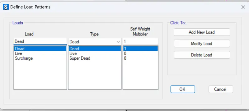
Click on DEFINE TAB
Click on Load Patterns
Define Load Patterns dialogue box opens
Add New Load: Surcharge
Press OK
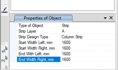
Click on ASSIGN TAB
Click on Shell Loads
Select Uniform
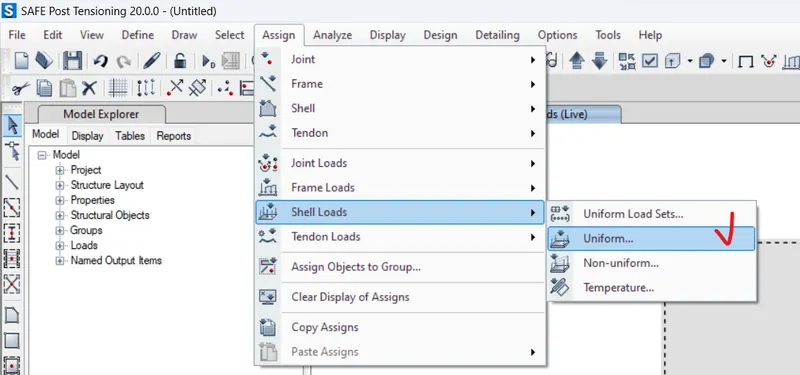
Shell Load Assignment dialogue box opens
Load pattern Name: surcharge
Load: 36 kN/m2
Click on Apply
Press OK
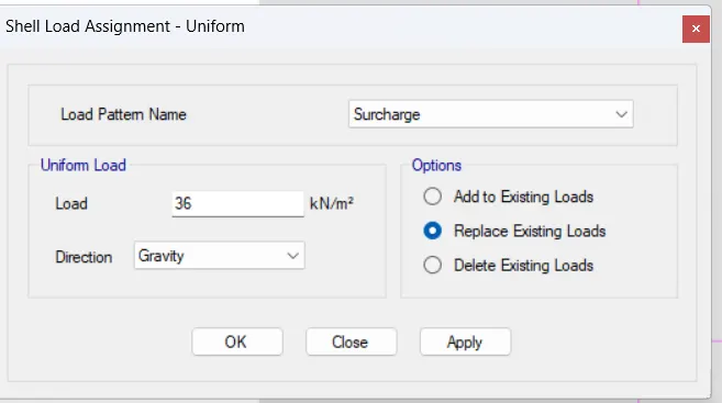
Click on DRAW TAB
Select Draw Design Strips
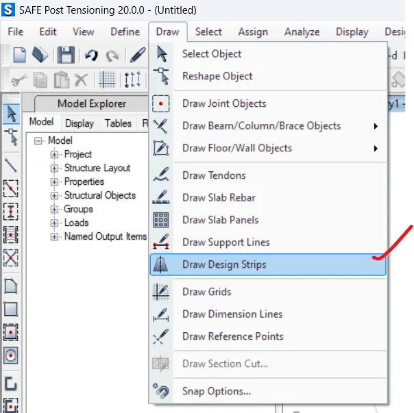
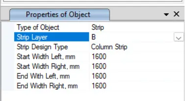
Change the data in the Properties of object
Width:1600mm
Strip Layer:A
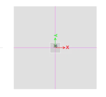
Draw Strip horizontally at centre
Change the data in the Properties of object
Width:1600mm
Strip Layer:B
Draw Strip Vertically at centre
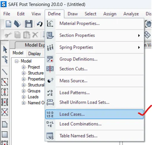
Click on DEFINE TAB
Click on Load Cases
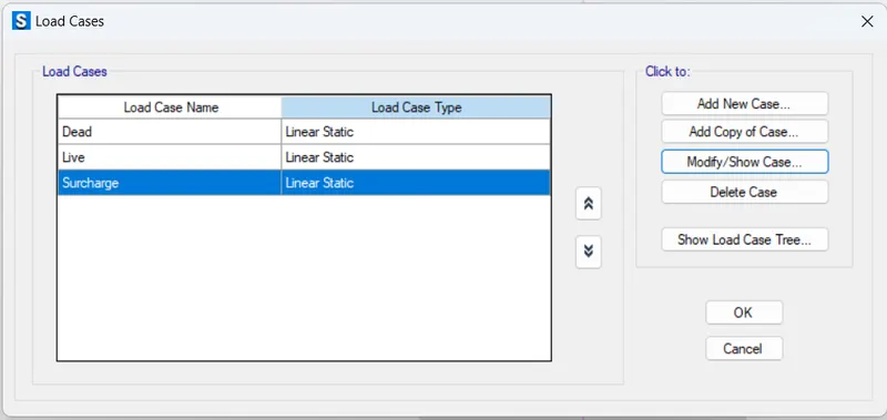
Load Cases dialogue box opens
Check all the loads
Press OK
Click on DEFINE TAB
Select Load Combinations
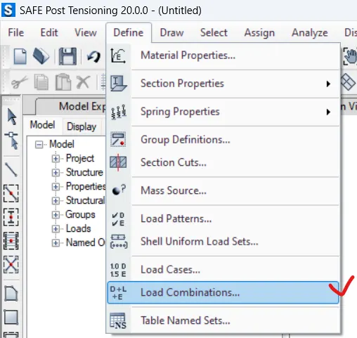
Load Combinations dialogue box opens
Add New Combo
Press OK
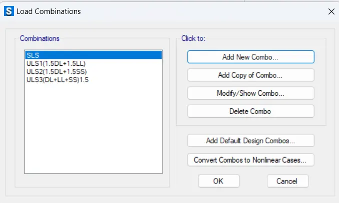
Click on ANALYSE TAB
Select Check Model
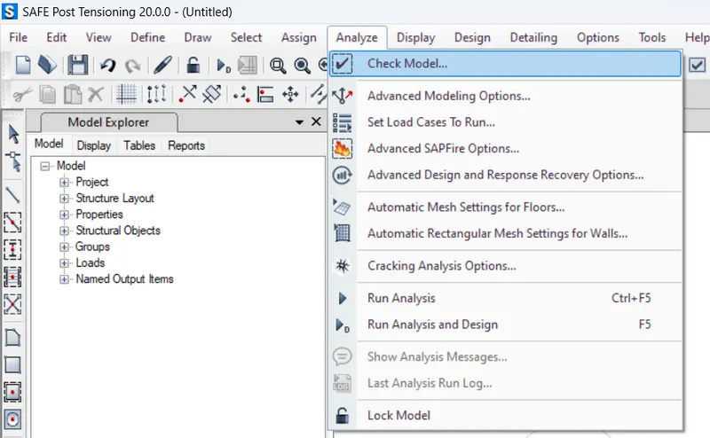
Check Model dialogue box opens
Select all
Press Ok
No warnings message were generated.

Click on ANALYSE TAB
Run the Analysis
RESULT: -
Modelled the isolated footing.
Analyzed and designed the footing and following checks are done.
- Safe bearing capacity under service load.
Bearing Stresses are within the limit of SBC
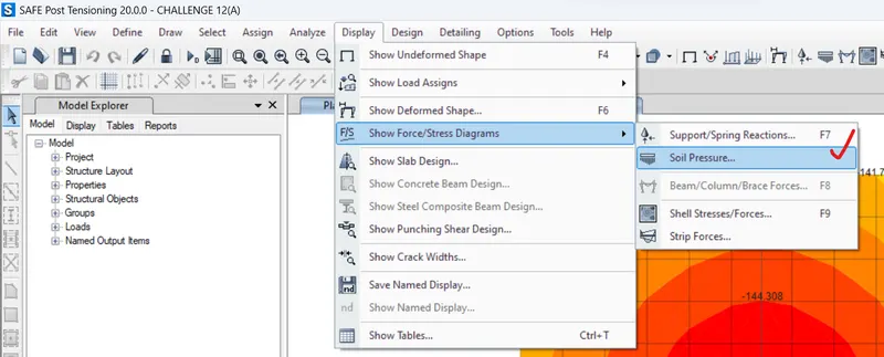
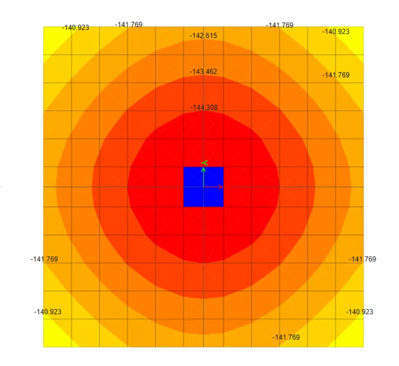
- Settlement under Service Load
Settlement is within the prescribes limit-50mm
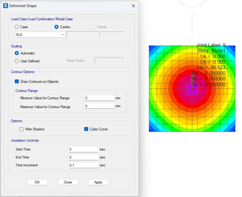
- Two way shear check
Punching Shear Ratio is less than 1
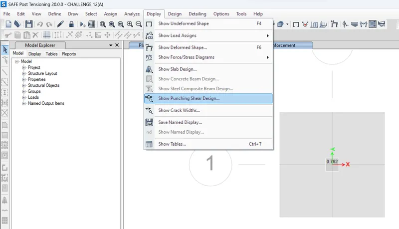
- Ultimate Bending Moment
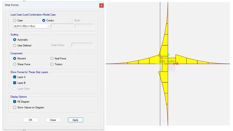
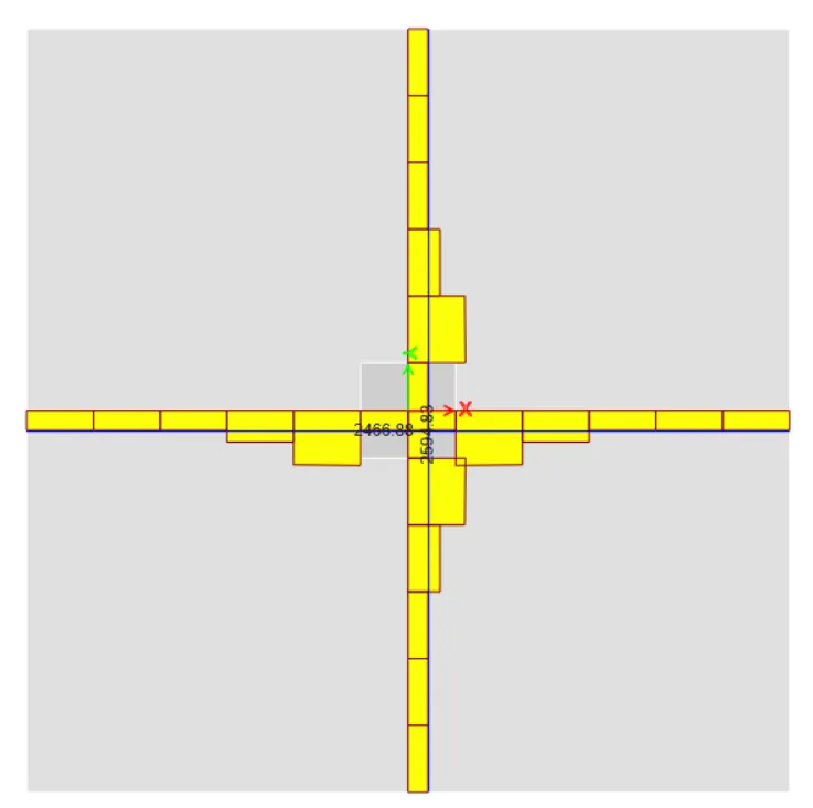
- Flexural Reinforcement Design
Provide 2466.8 mm2/m along Strip A
Provide 2594.83 mm2/m along Strip B
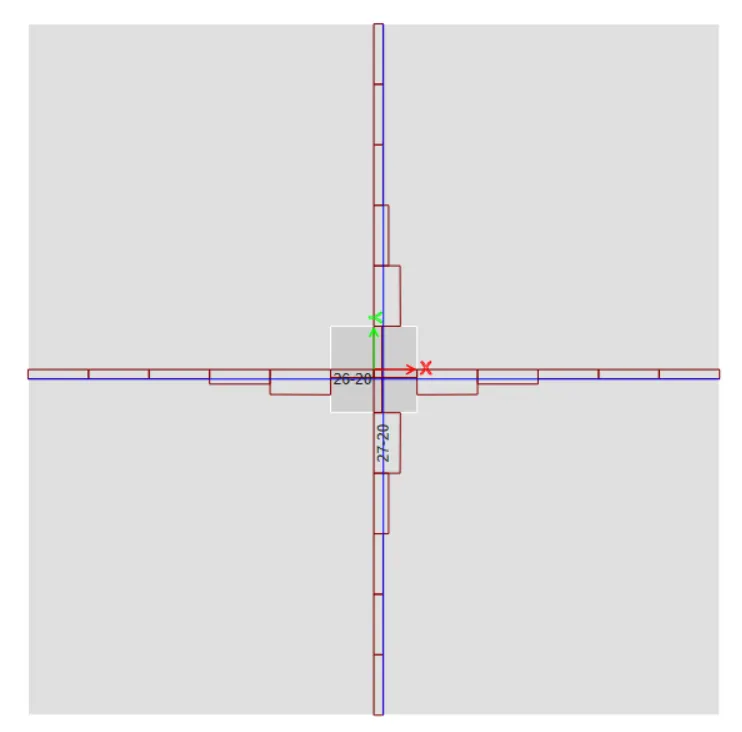
So, Provide 20mm dia bars @ 120mm spacing c/c.
Q2]
AIM: -
Analyse and Design the pile cap on SAFE to evaluate the following:
- Pile group to be used
- Depth of pile cap
- Longitudinal steel on top and bottom face in both directions
PROCEDURE: -
GIVEN DATA
Column size= 600x600
Unfactored gravity load (DL+LL) = 1175 KN
Pile Length = 16m
Pile diameter = 500mm
Pile load carrying capacity = 200 KN.
Grade of concrete = M25
No of piles required= unfactored load with self weight/individual pile capacity
= 1175*1.1/200
= 6.5
Consider 8 piles for symmetric placement of piles under pile cap
Take centre to centre distance between piles = 3*pile diameter
= 3*500 = 1500mm
Edge distance from pile centre= 1* pile diameter = 500mm
Area of each pile = `pi/4*d^2`
= `pi/4*(500)^2`
=196349.5mm2
E = 5000√fck = 25000 N/mm2
Spring constant (k) = EA/L
= (25000 x 196349.5)/16000
= 306796.09 N/mm
= 306796.09 kN/m
Assume pile cap depth = 800mm
Length = 500+1500+1500+500 = 4000m
Width = 500+1500+1500+500 = 4000mm
Open the SAFE Application and select New Model
Model Initialization dialogue box opens
Display Units: Metric SI
Concrete Design Code: IS 456-2000
steel design code: BS-5950
Press O.K.
Press O.K.
Now, New Model Quick Template dialogue box opens
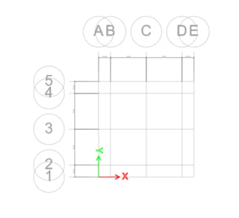
Select Custom Grid Spacing
Click on Edit Grid Data
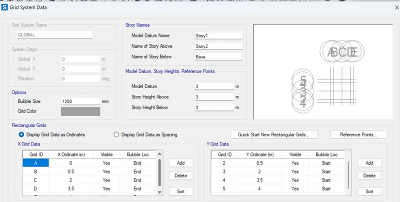
Grid System Data dialogue box opens
Under Rectangular Grids, Select Display grid Data as Spacing
Under X Grid Data column enter the data as per given data
Under Y Grid Data column enter the data as per given data
After entering the Grid Data press OK
Click on DESIGN TAB
Click on concrete slab/Beam Design
Select View/Revise Preferences option
Concrete design Preferences dialogue box opens
Change the required data
Press O.K.
Click on the Define Tab
Select Material Properties
Define Materials dialogue box opens
Click on Add New Material
Add New Material Property dialogue box opens
Region: India
Material Type: Concrete
Standard: Indian
Grade: M25
After entering the data, press OK
Click on Add New Material
Add New Material Property dialogue box opens
Region: India
Material Type: Rebar
Standard: Indian
Grade: HYSD Grade 500
After entering the data, press OK
Click on the Define Tab
Click on Section Properties and select Slab Sections
Slab Properties dialogue box opens
Click on Add New Property
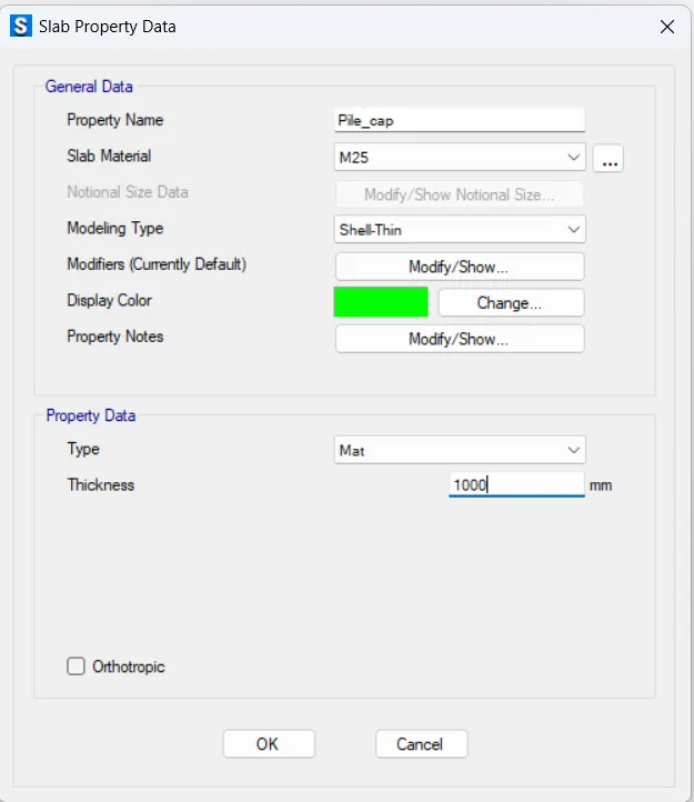
Slab property Data dialogue box opens
Propert name: Pile_cap
Slab material: M25
Type: Mat
Thickness: 1000mm
Press O.K
Click on Add New Property
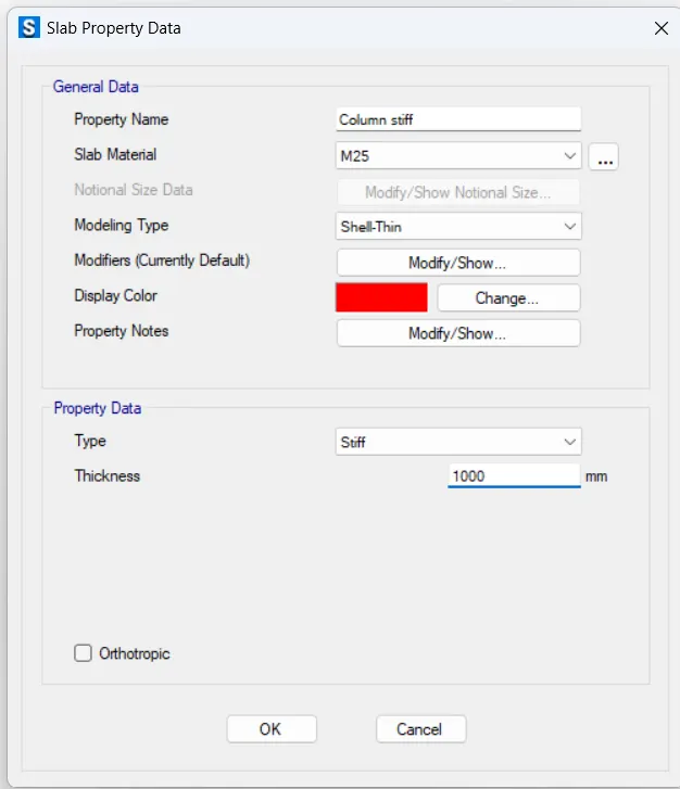
Slab property Data dialogue box opens
Propert name: Stiff1
Slab material: M25
Type: Stiff
Thickness: 1000mm
Press O.K
Click on Add New Property
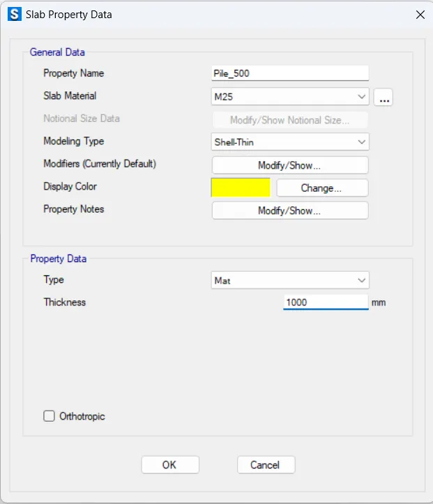
Slab property Data dialogue box opens
Propert name: Pile_500
Slab material: M25
Type: Mat
Thickness: 1000mm
Press O.K
Click on DRAW TAB
Click on Draw Floor/Wall objects
Select Draw Rectangular Floor/wall tool
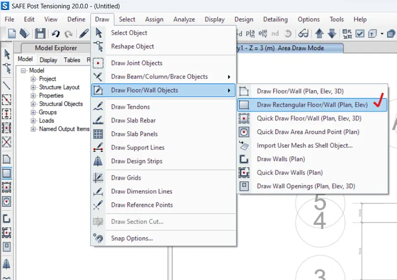
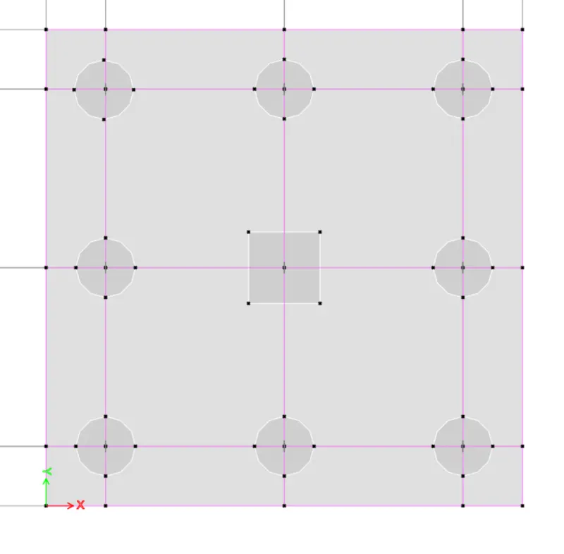
Draw Pile cap in the model screen.
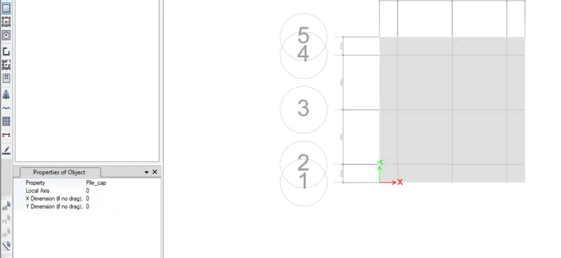
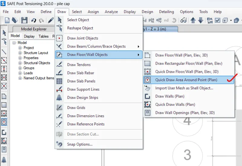
Click on DRAW TAB
Click on Draw Floor/Wall objects
Select Quick Draw Area Around Point
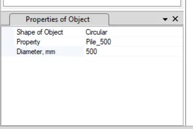
Select the data as per requirement in Properties of Object
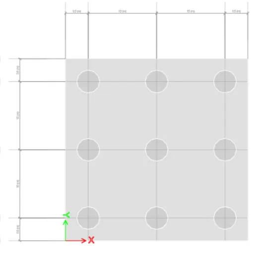
Click on DRAW TAB
Click on Draw Floor/Wall objects
Select Quick Draw Area Around Point
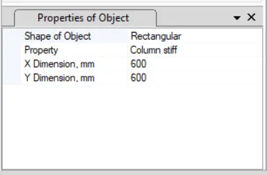
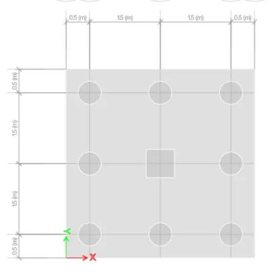
Click on DEFINE TAB
Click on Spring Properties > Point Springs
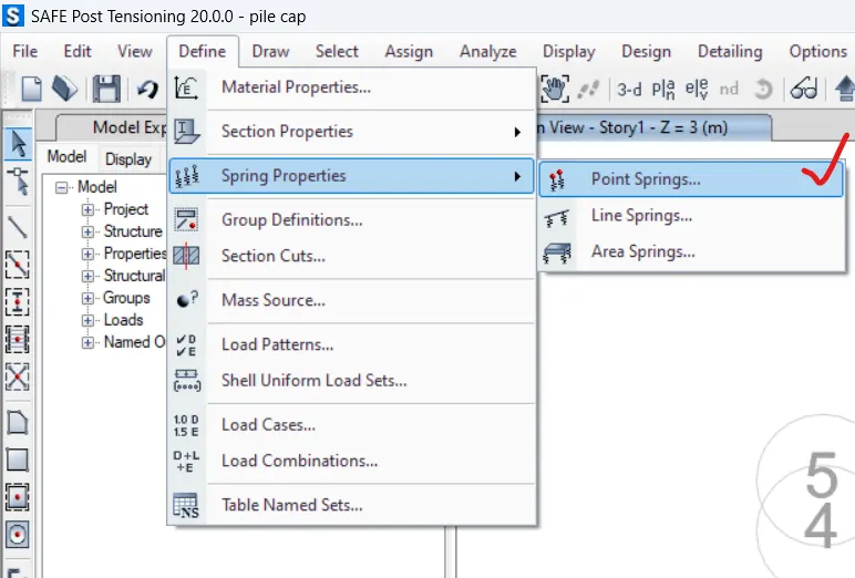
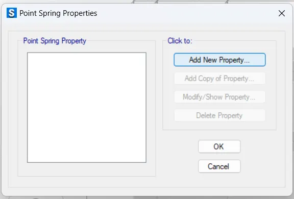
Point Spring Properties Dialogue box opens
Click on Add New Property
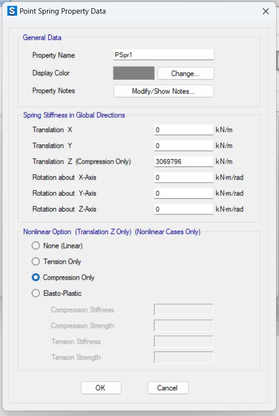
Point Spring Property Data dialogue box opens
Stiffness Spring Z: 306796 kN/m
Compression only
Press OK
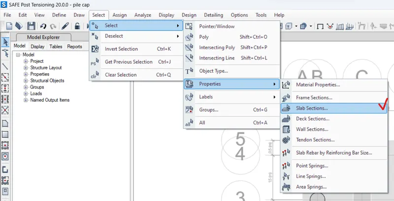
Click on SELECT TAB
Click on Select > Properties > Slab Section
Select by Slab Property dialogue box opens
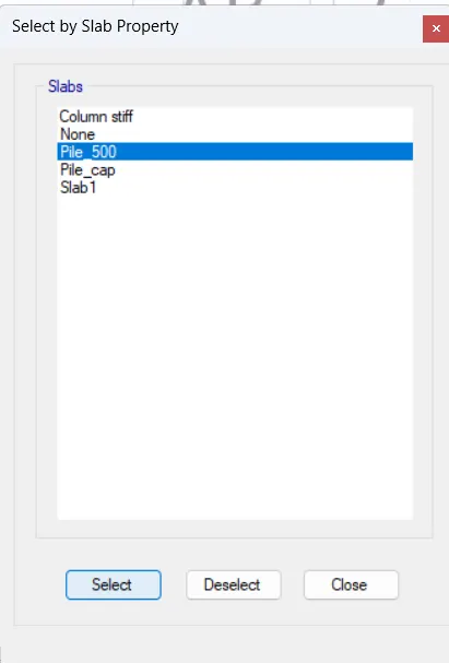
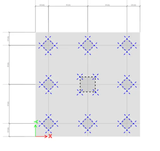
Assign Spring Properties to Piles
Click on ASSIGN TAB
Click on Joint > Springs
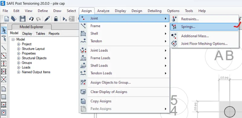
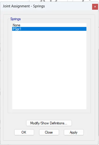
Joint Assignment Spring dialogue box opens
Select the Spring
Click on Apply
Press OK
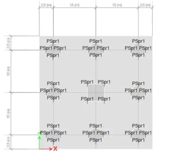
Draw Point at centre of the Column
Click on DRAW TAB
Select Draw Joint Objects
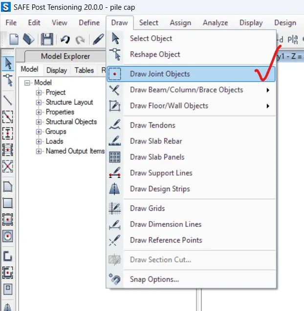
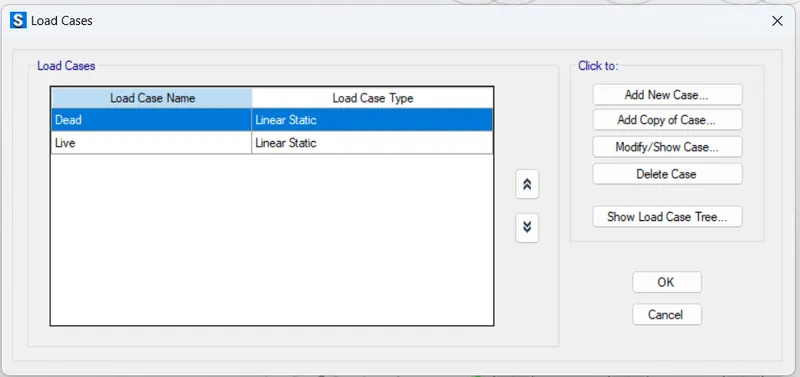
Click on DEFINE TAB
Click on Load Cases
Load Cases dialogue box opens
Check all the loads
Press OK
Select point at centre of the column.
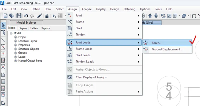
Assign Loads centre of the Column.
Click on ASSIGN TAB
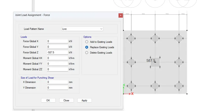
Joint Loads > Force
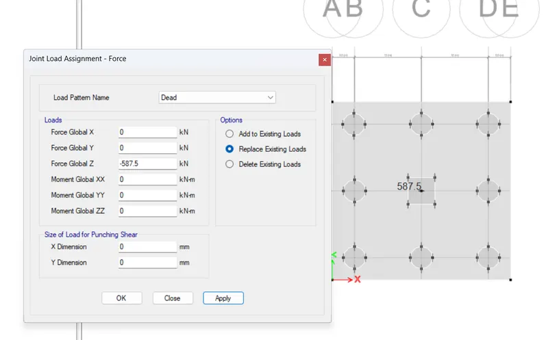
Join Load Assignment-Force dialogue box opens
Pattern name: dead
Force Z: -587.5kN
Click Apply
Press OK
Pattern name: Live
Force Z: -587.5kN
Click Apply
Press OK
Click on DEFINE TAB
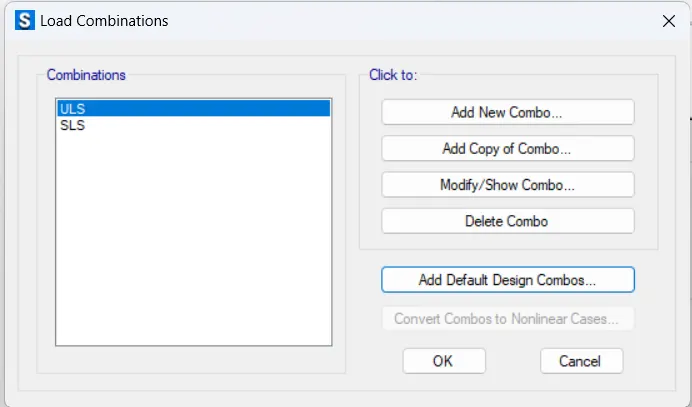
Select Load Combinations
Load Combinations dialogue box opens
Add New Combo
Press OK
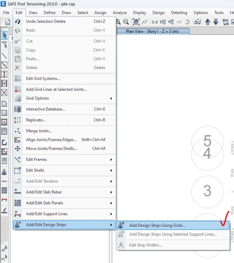
Click on EDIT TAB
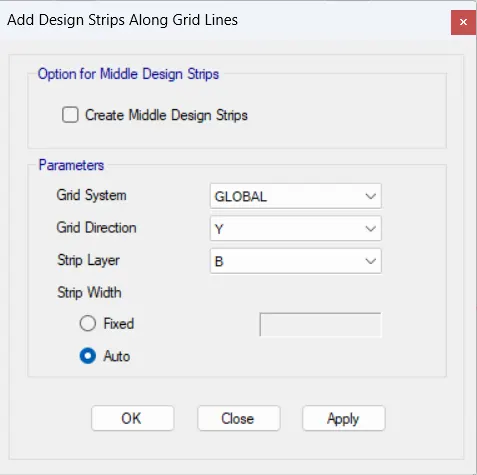
Click on Add/edit Design Strips > Add design Strips using Grids
Add Design Strips Along Grid Lines dialgue box opens
Grid direction: X
Strip layer: A
Click on Apply
Press OK
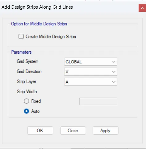
Grid direction: Y
Strip layer: B
Click on Apply
Press OK
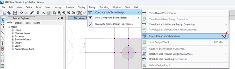
Click on DESIGN TAB
Select Design Combinations
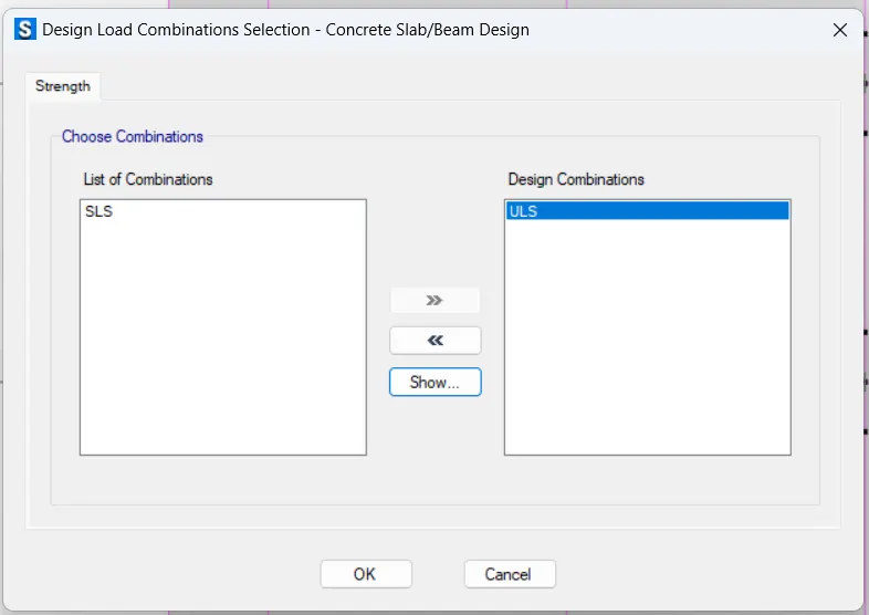
Design Load Combinations Selection dialogue box opens
Select the Design combinations
Press OK
Click on ANALYSE TAB
Select Check Model
Check Model dialogue box opens
Select all
Press Ok
No warnings message were generated.
Click on ANALYSE TAB
Run the Analysis
RESULT: -
Modelled the Pile footing.
Analyzed and designed the footing and following checks are done.
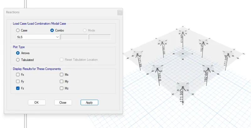
- Pilce capacity under service load.
Reactions are within the limit of Pilce capacity = 200kN
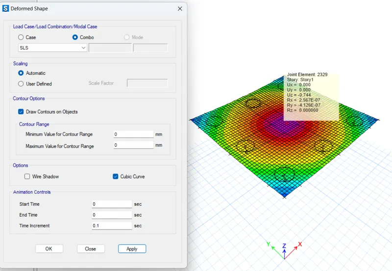
- Settlement under Service Load
Settlement is within the prescribes limit-50mm
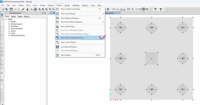
- Two way shear check
Punching Shear Ratio is less than 1
- Ultimate Bending Moment
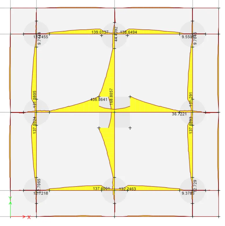
- Flexural Reinforcement Design
Check for reinforcement Ultimate limit state.
Minimum reinforcement should be 0.12% as per IS-456.