Foundation Design using SAFE
Question 1
AIM
To model the isolated footing provided in week 11 challenge on SAFE.
INTRODUCTION
SAFE offers a single user interface to perform modeling, analysis, design and reporting. A new model explorer is available for quick access to objects, properties and forms. It is ideal for modeling foundations, basemats, and footings. Easily model soil supports and zero tension soil models with uplift analysis. The area assignment of soil supports is based on the subgrade modulus, and they automatically adjust whenever the mesh changes. Basemat foundation models can include pedestals, walls, columns, beams, and piles in addition to the foundation area.
CALCULATIONS
Data from week 11 challenge
|
Data required for SAFE analysis & Design
|
PROCEDURE
- Open SAFE Software
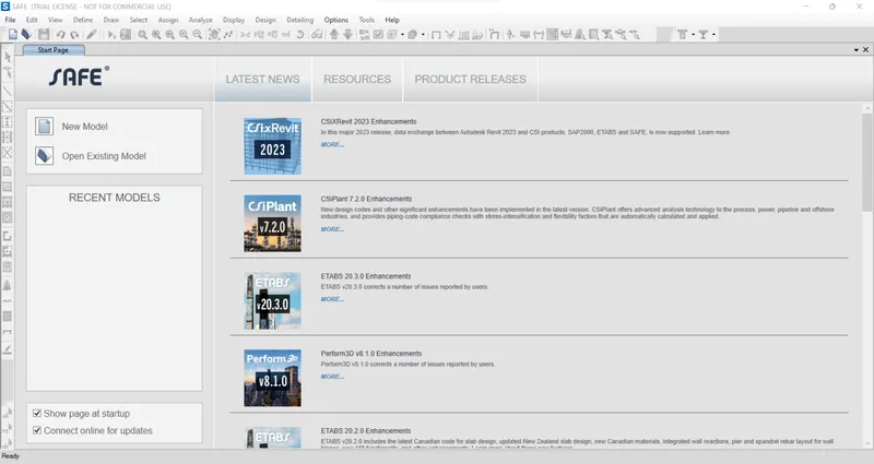
STEP 1: Model Initialization
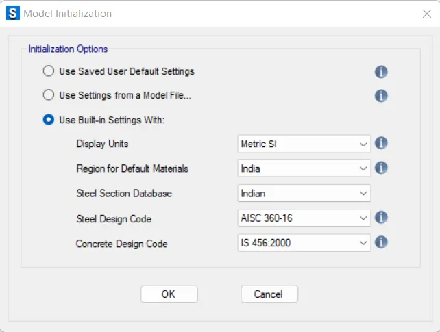
- Click 'New Model' and select 'Use Built-in Settings With:'
- Assign all options as given below
- Click 'OK'
- Click 'Single Footing'
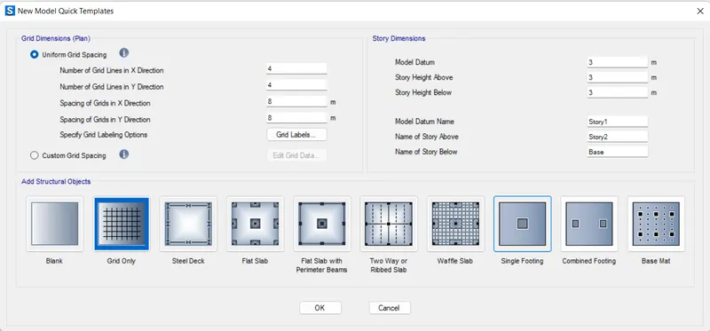
- Assign all options as given below
- Click 'OK'
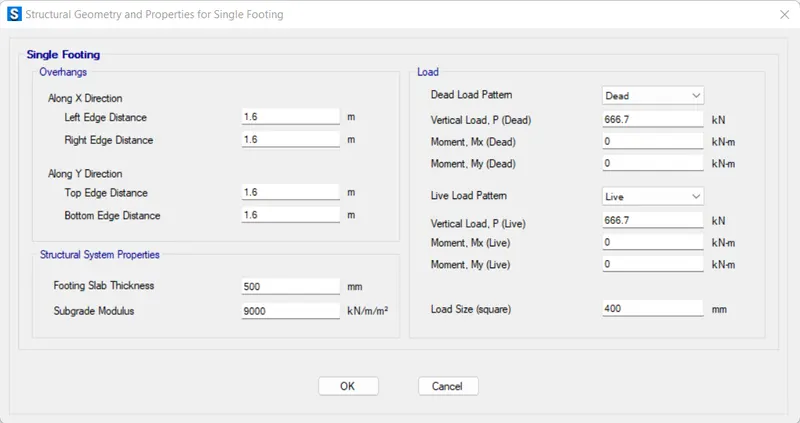
- Click 'OK'
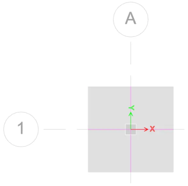
STEP 2: Material Properties
- Click 'Material Properties' under the 'Define' tab

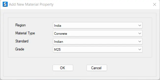
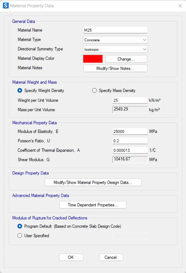
M25
- Click 'Add New Material'
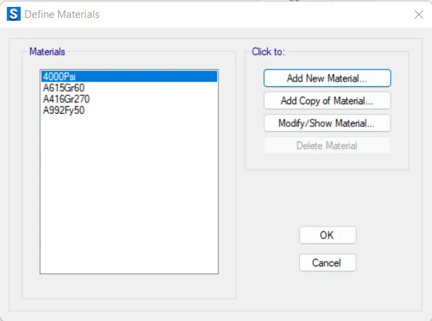
- Assign all options as given below
- Click 'OK'
- Assign all options as given below
- Click 'OK'
Grade 500
- Click 'Add New Material'
- Assign all options as given below
- Click 'OK'
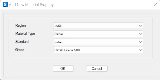
- Assign all options as given below
- Click 'OK'
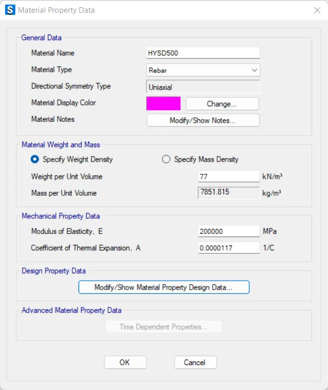
- Click 'OK'
STEP 3: Add Slab Properties
- Click 'Slab Section' in the 'Section Properties' under the 'Define' tab
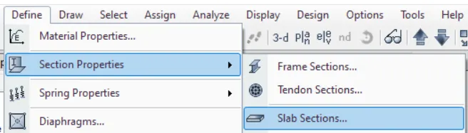
Footing
- Select 'Footing1' and click 'Modify/Show Property'
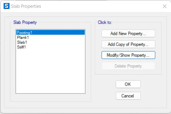
- Assign all options as given below
- Click 'OK'
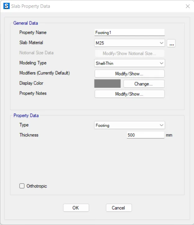
- Click 'OK'
Column
- Select 'Stiff1' and click 'Modify/Show Property'
- Assign all options as given below
- Click 'OK'
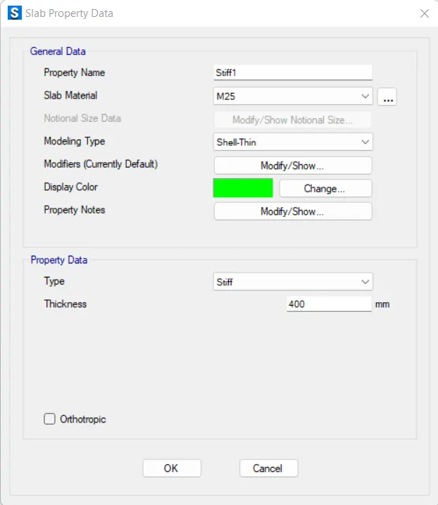
- Click 'OK'
STEP 4: Add Soil Subgrade Modules/Area Spring Property Data
- Click 'Area Springs' in the 'Spring Properties' under the 'Define' tab
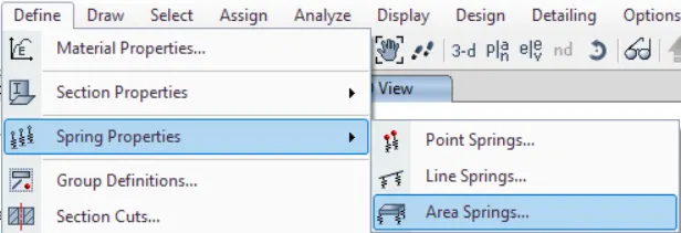
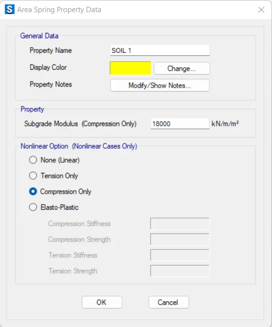
- Assign all options as given below
- Click 'OK'
STEP 5: Add Load Patterns
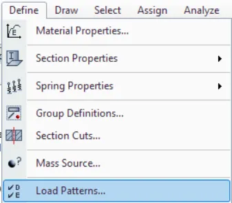
- Click 'Load Patterns' under the 'Define' tab
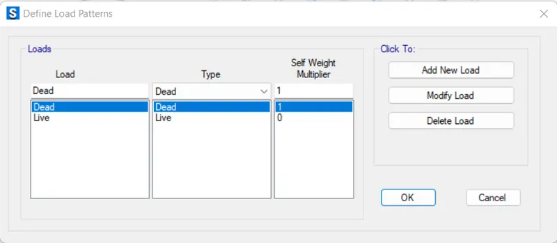
- Assign all options as given below
- Click 'OK'
STEP 6: Add Load Combinations
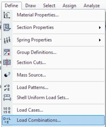
- Click 'Load Combinations' under the 'Define' tab
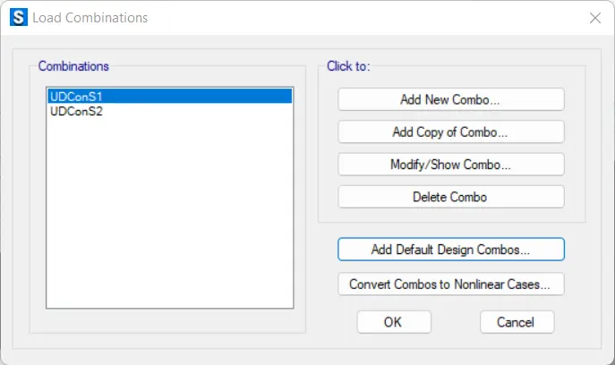
- Click 'Add Default Design Combos'
STEP 7: Run Analysis
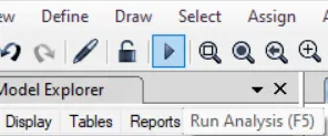
- Click 'Run Analysis' from top menu
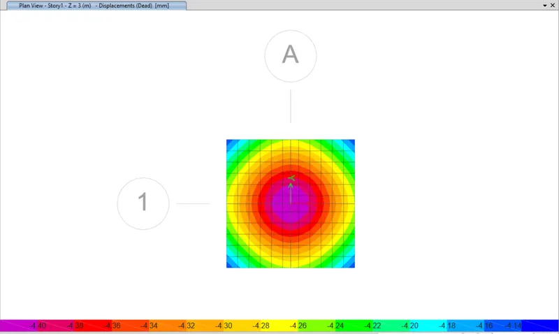
STEP 8: Soil Pressure
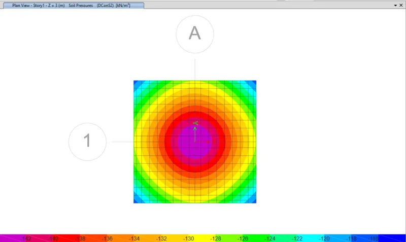
- Click 'Display Soil Pressure' in the top menu
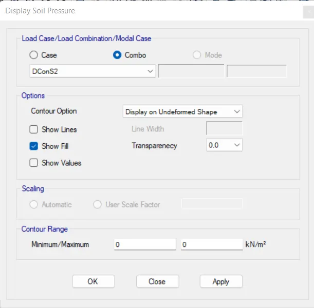
- Assign all options as given below
- Click 'OK'
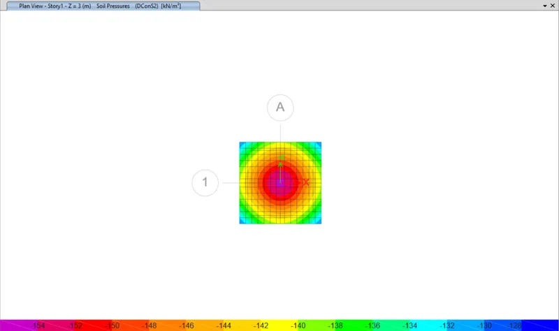
- 154 kN/m2 > 150 kN/m2
- Therefore, increase the area (4.2mX4.2m)
STEP 9: Punching Shear
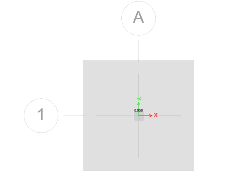
- Click 'Show Punching Shear Design' in the top menu
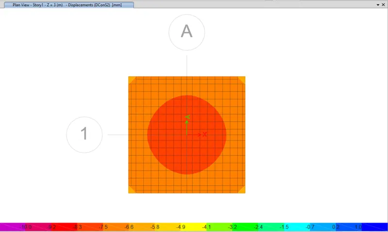
STEP 10: Deformed Shape
- Click 'Show Deformed Shape' in the top menu
STEP 11: Design Strips
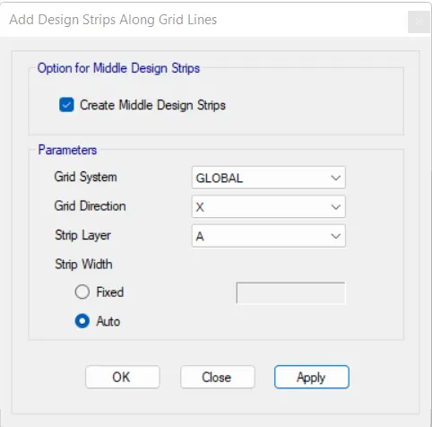
- Click 'Add Design Strips' under the 'Edit' tab
- Assign all options as given below
- Click 'OK'
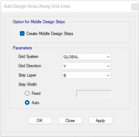
- Assign all options as given below
- Click 'OK'
- Run the model again
- Click 'Display Strip Forces' in the top menu
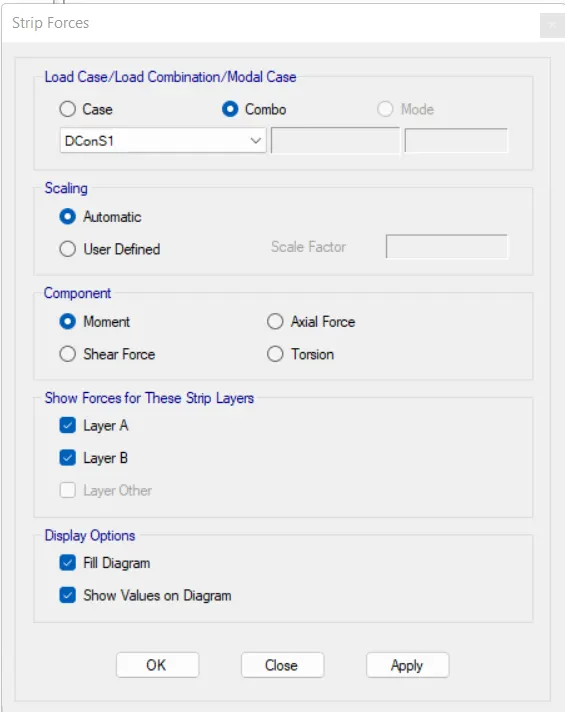
- Assign all options as given below
- Click 'OK'
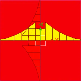
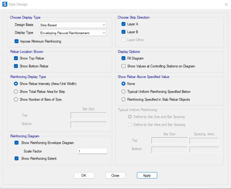
- Click 'Slab Design' in the top menu
- Assign all options as given below
- Click 'OK'
RESULTS
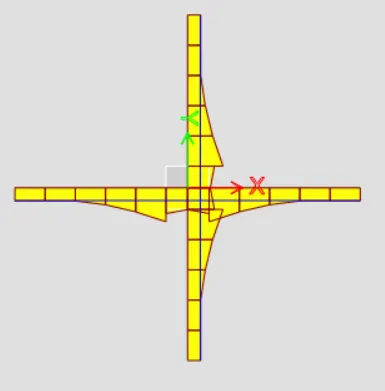
The isolated footing provided in week 11 challenge is modeled and analysed on SAFE. The graphs needed to obtain result for the checks are given in the procedure. The final result is shown in the table below.
| Checks | Results |
| Safe bearing capacity under Service load | Safe |
| Settlement under Service load | Safe |
| Two way shear check (Punching shear) | Safe |
| Ultimate bending moment | Safe |
| Flexural reinforcement design for Footing slab | Safe |
Question 2
AIM
To model, analyse and design the pile cap on SAFE.
INTRODUCTION
SAFE offers a single user interface to perform modeling, analysis, design and reporting. A new model explorer is available for quick access to objects, properties and forms. It is ideal for modeling foundations, basemats, and footings. Easily model soil supports and zero tension soil models with uplift analysis. The area assignment of soil supports is based on the subgrade modulus, and they automatically adjust whenever the mesh changes. Basemat foundation models can include pedestals, walls, columns, beams, and piles in addition to the foundation area.
CALCULATIONS
Data required for SAFE analysis & Design
Calculations:
i) As per IS 2911 (part 2) the spacing between the piles is taken as 2.5 times the diameter of pile ii) The edge spacing we have assume it as 300 mm. |
PROCEDURE
- Open SAFE Software
STEP 1: Model Initialization
- Click 'New Model' and select 'Use Built-in Settings With:'
- Assign all options as given below
- Click 'OK'
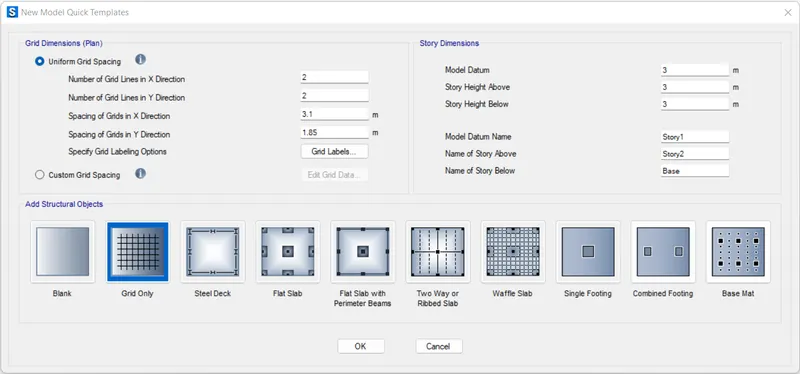
- Click 'Grid Only'
- Assign all options as given below
- Click 'OK'
- Click 'OK'
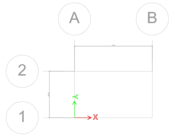
STEP 2: Material Properties
- Click 'Material Properties' under the 'Define' tab
M25
- Click 'Add New Material'
- Assign all options as given below
- Click 'OK'
- Assign all options as given below
- Click 'OK'
Grade 500
- Click 'Add New Material'
- Assign all options as given below
- Click 'OK'
- Assign all options as given below
- Click 'OK'
- Click 'OK'
STEP 3: Add Slab Properties
- Click 'Slab Section' in the 'Section Properties' under the 'Define' tab
Footing
- Select 'Footing1' and click 'Modify/Show Property'
- Assign all options as given below
- Click 'OK'
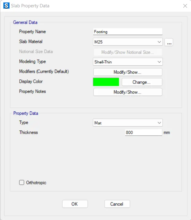
- Click 'OK'
Column
- Select 'Stiff1' and click 'Modify/Show Property'
- Assign all options as given below
- Click 'OK'
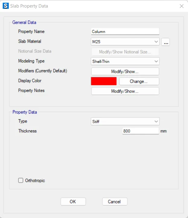
- Click 'OK'
Pile Cap
- Click 'Add New Property'
- Assign all options as given below
- Click 'OK'
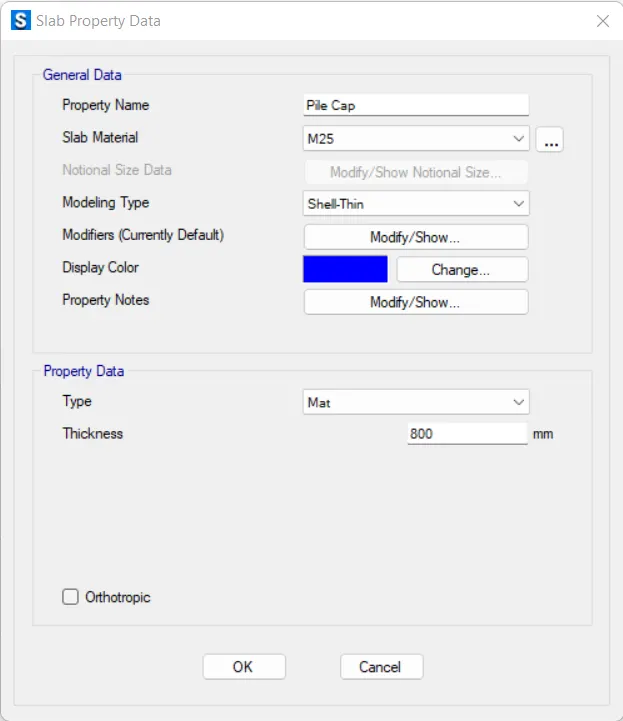
- Click 'OK'
STEP 4: Draw Slab Properties
- Click 'Quick Draw Floor' in the side menu
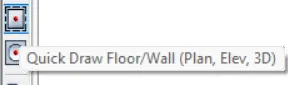
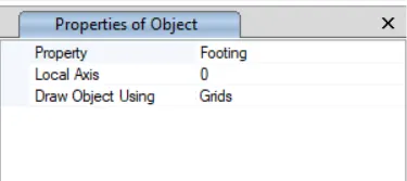
- Assign 'Footing' as the property
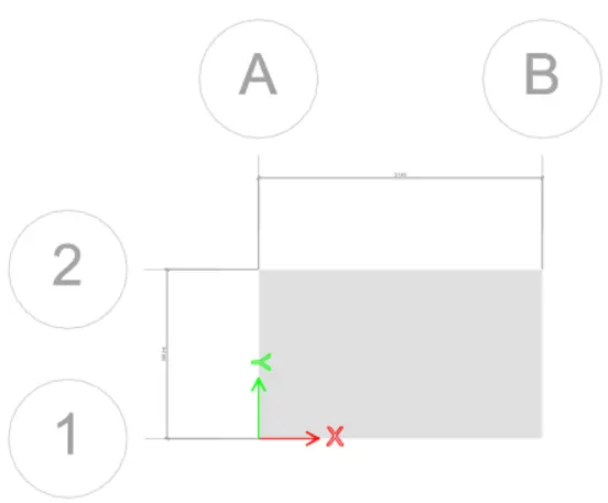
- Click inside all the grids
STEP 5: Add Points
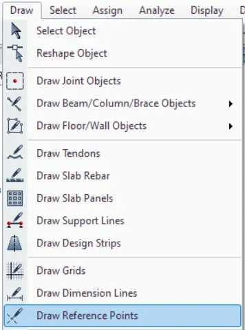
- Click 'Draw Reference Points' under the 'Draw' tab
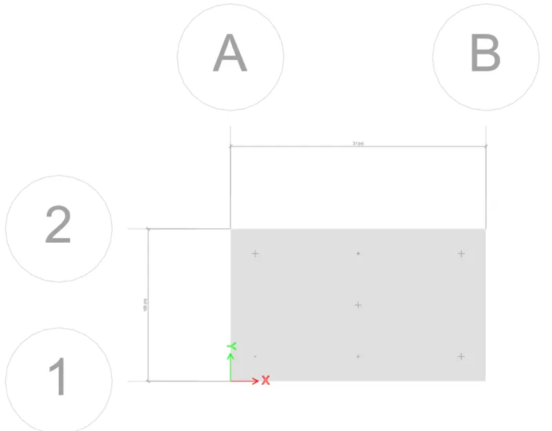
- Assign appropriate values for X and Y, draw the points
STEP 6: Add Column Slabs
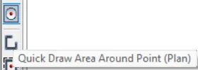
- Click 'Quick Draw Area Around Point'
- Assign all options as given below
- Click 'OK'
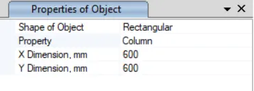
- Draw column in the center point
- Assign all options as given below
- Click 'OK'
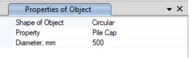
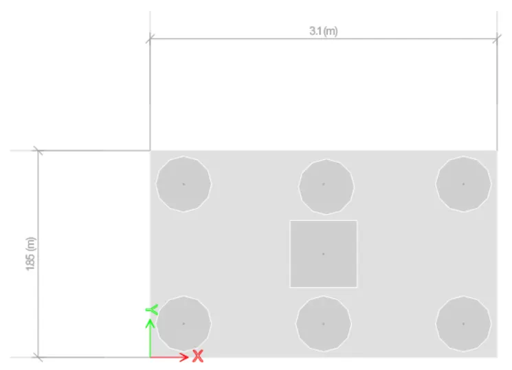
- Draw the pile caps in the reference points
STEP 7: Add and Assign Point Spring Property Data
- Click 'Point Springs' in the 'Spring Properties' under the 'Define' tab
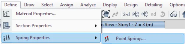
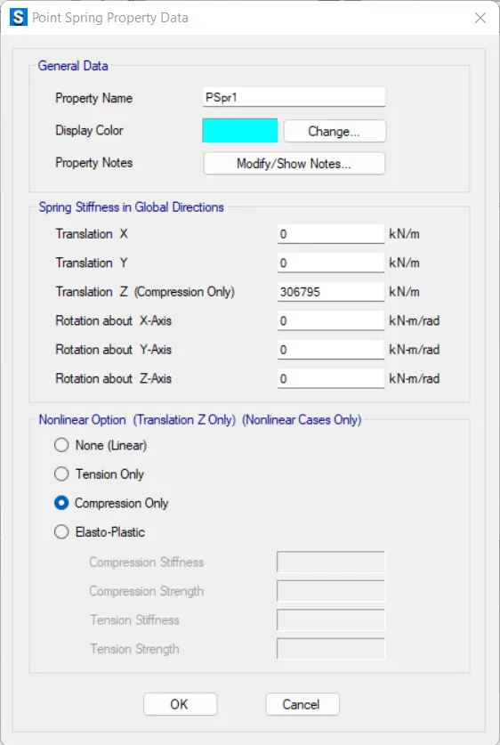
- Assign all options as given below
- Click 'OK'
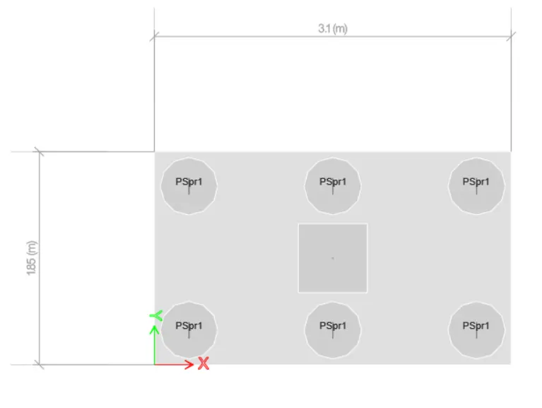
- Select the center points of all pile caps
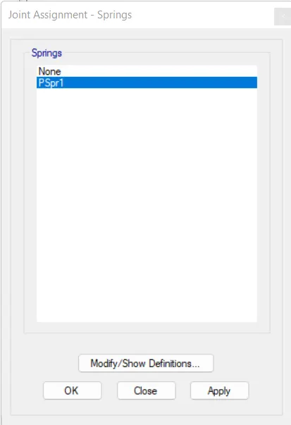
- Click 'Springs' in the 'Joint' under the 'Assign' tab

- Select 'PSpr1' and click 'OK'
STEP 8: Assign Loads
- Select the center of the column
- Click 'Force' in the 'Joint Loads' under the 'Assign' tab
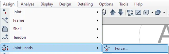
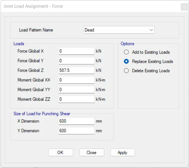
- Assign all options as given below
- Click 'OK'
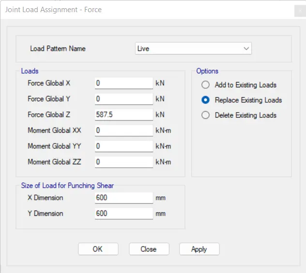
- Assign all options as given below
- Click 'OK'
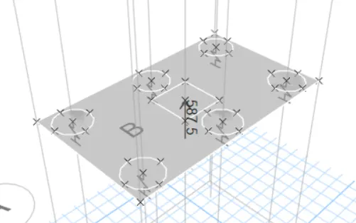
STEP 9: Add Load Combination
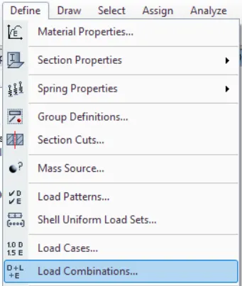
- Click 'Load Combinations' under the 'Define' tab
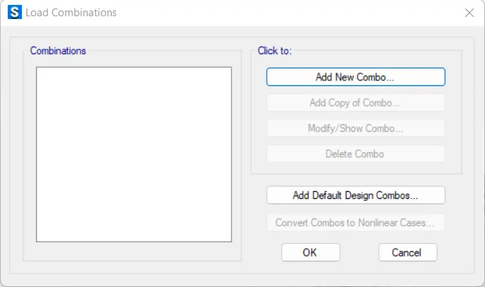
- Click 'Add New Combo'
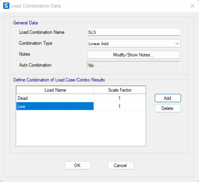
- Assign all options as given below
- Click 'OK'
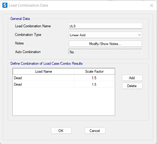
- Click 'Add New Combo'
- Assign all options as given below
- Click 'OK'
- Click 'OK'
STEP 10: Run Analysis
- Click 'Run Analysis' from top menu
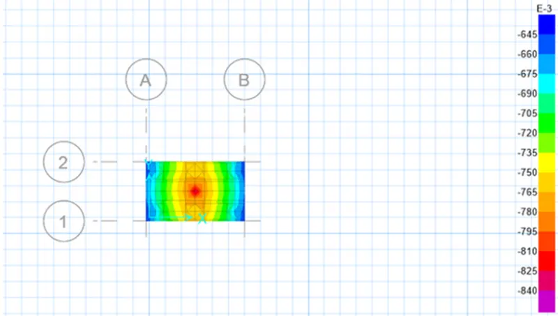
STEP 11: Punching Shear
- Click 'Show Punching Shear Design' in the top menu
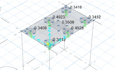
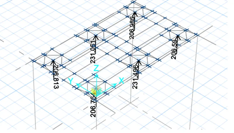
STEP 12: Joint Reaction
STEP 13: Design Strips
- Click 'Add Design Strips' under the 'Edit' tab
- Assign all options as given below
- Click 'OK'
- Assign all options as given below
- Click 'OK'
- Run the model again
- Click 'Display Strip Forces' in the top menu
- Assign all options as given below
- Click 'OK'
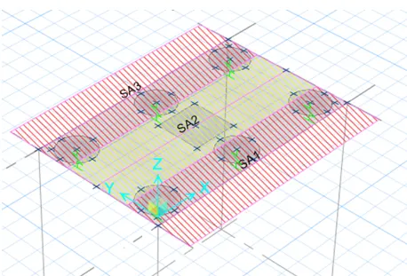
- Click 'Slab Design' in the top menu
- Assign all options as given below
- Click 'OK'
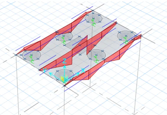
Layer A
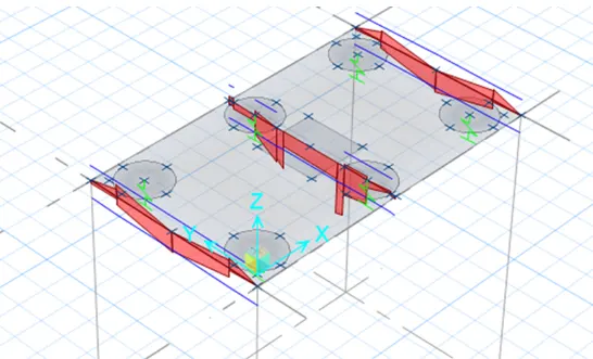
Layer B
RESULTS
The pile cap is modeled and analysed on SAFE. The graphs needed to obtain result for the checks are given in the procedure. The final result is shown in the table below.
| Checks | Results |
| Individual pile capacity under Service load | Safe |
| Settlement under Service load | Safe |
| Two way shear check (Punching shear) | Safe |
| Flexural reinforcement design for Footing slab | Safe |