Forward kinematics of 2R Robotic arm
AIM
Write a program in python to simulate the forward kinematics of a 2R Robotic Arm and also animate file of the plot.
INITIAL STUDY
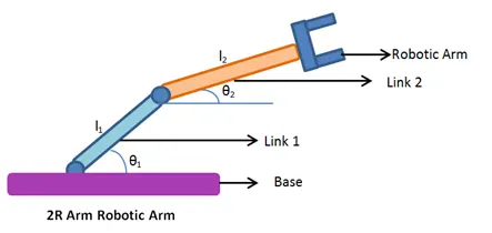
Figure 1:2R robotic arm
A two degree of freedom robot arm is described in Figure above,which consists primarily of two links with the following specifications in OXY coordinates:
l1 = 1 m is the length of the first link.
l2 = 0.5 m is the length of the second link.
𝑚1 = 1 kg is the mass of the first link.
𝑚2 = 1 kg is the link of the second link.
𝜃1 = the rotation angle of the first link.
𝜃2 = is the rotation angle of the second link.
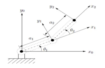
figure 2: 2R robotic arm coordinates
Robot kinematics are mainly of the following two types: forward kinematics and inverse kinematics. Forward kinematics is also known as direct kinematics. In forward kinematics, the length of each link and the angle of each joint is given and we have to calculate the position of any point in the work volume of the robot.Thus forward kinematics is the method for determining the orientation and position of the end effector, given the joint angles and link lengths of the robot arm.
OBJECTIVE
To write a program in python to simulate the forward kinematics of a 2R Robotic Arm and to animate the file of the plots obtained.Here a familiarisation with the 2R robotic arm and its programming by controlling the coordinates in workspace is studied.
PROCEDURE
The program created for the 2R robotic arm simulation is given below:
# A program in python to simulate the forward kinematics of a 2R Robotic Arm
# created by Lakshmi Rajan P

#importing the required modules:math to do mathematical calculations and matplotlib to create the needed plots
import math
import matplotlib.pyplot as plt

#The angle through which the link is made to rotate is assigned from 0 to 90 radians
theta_start=0
theta_end=(math.pi)/2

#the length of first link is assigned as l1, and length of link2 with manipulator is assigned as l2
l1=1
l2=0.5

#The link with manipulator is provided with 10 angular movements ie,10,20,30...90
n=10

#Two null arrays are assigned to store the values of theta 1 and theta 2
theta1=[]
theta2=[]

# A for loop is run to generate the required theta1 and theta2 values by an equation and the returned values are added in the null arras mentioned above.
for i in range(0,n):
	tmp=theta_start+i*(theta_end-theta_start)/(n-1)
	theta1.append(tmp)
	theta2.append(tmp)

#The base values are assigned as origin with coordinates as (0,0)
x0=0
y0=0

#A counter ct is assigned to store the plots obtained after each iteration
ct=1

#The following for loops are carried out to initiate each theta1 and theta2 values and obtain the respective coordinates of link joints.
#here the link 1 joint with link 2 is given the coordinates (x1,y1) and that of the manipulator is given as (x2,y2)

for t1 in theta1:
	for t2 in theta2:

		x1=l1*math.cos(t1)
		y1=l1*math.sin(t1)

		x2=x1+l1*math.cos(t2)
		y2=y1+l2*math.sin(t2)
#The position of the links are assigned with the counter value assigned to a string ct
		filename=str(ct)+'.png'
		ct+=1
# Now the plots are obtained in different files by the following command
		plt.figure()
#Plotting the coordinate values obtained to get the required link positions
		plt.plot([x0,x1],[y0,y1])
		plt.plot([x1,x2],[y1,y2])
# The values of x and y are linited to the first quadrant by limiting its end values
		plt.xlim([0,2])
		plt.ylim([0,2])
#Labelled x axis as 'x axis ' and y axis as 'y axis'
		plt.xlabel('x axis')
		plt.ylabel('y axis')
		plt.savefig(filename)
1)First import the two modules required for running the program ,which are matplotlib and math.Here matplotlib is used to plot the different orientations of the robotic arm and math is used to perform various numerical calculations.The start angle of links are from base at (0,0) to an angle of 90.
2)Now as per the given figure 2,we have the link 1 and link 2 oriented with the x axis at theta 1 degrees and theta 2 degrees.So we initialise those values.Link l1 and link l2 is also given its values.
3)We are assigning 10 positions for theta 1 and theta 2,which varies between 0 to 90 as 10,20,30,....90.
4)Next we admit a counter variable ct whixh gets incremented after every iteration.And a for loop is run to add values to the empty arrays theta1 and theta2.
5)Now for every theta1 and theta2 saved as t1 and t2 after ever iteration we obtain the values of coordinates of link joints and thus different orientations of the robotic arm is got.
6)After iterating for loop ,we assign the values of iteration to a filename which is assigned at ct.png and each plot of different coordinates is saved in it.
7)we use matplotlib module to plot the figures and the x axis limit and the axis limit is limited to first quadrant from 0 to 2.
8)Now we create an animation using all the plots by converting them to a gif file.
OUTPUT
The output on the screen appears as below:
C:UsersLakshmiOneDriveDesktoppython codesforwardkinematics_attempt.py:51: RuntimeWarning: More than 20 figures have been opened. Figures created through the pyplot interface (`matplotlib.pyplot.figure`) are retained until explicitly closed and may consume too much memory. (To control this warning, see the rcParam `figure.max_open_warning`).
  plt.figure()
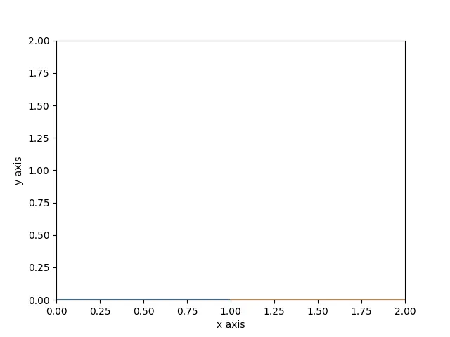
The final output we get are 100 plots of different arm positions and we created an animation using that plots to a single gif file attached.