Flow over an airfoil
OBJECTIVE
- Model the flow over a NACA0017 airfoil
- For the angle of attacks 0,2,4,6,8,10 compare the lift and drag forces
THEORY
Airfoil, also spelled Aerofoil, shaped surface, such as an airplane wing, tail, or propeller blade, that produces lift and drag when moved through the air. An airfoil produces a lifting force that acts at right angles to the airstream and a dragging force that acts in the same direction as the airstream.
High-speed aircraft usually employ low-drag, low-lift airfoils that are thin and streamlined. Slow aircraft that carry heavy loads use thicker airfoils with high drag and high lift.
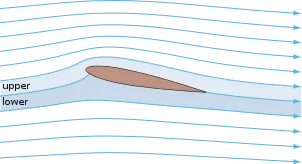
- Streamlines around a NACA 0012 airfoil at moderate angle of attack
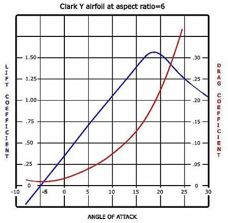
- Lift and drag curves for a typical airfoil
PROCEDURE
- Geometry creation
- Importing the co-ordinates of the airfoli (Insert -> Curve -> Curve through XYZ points -> select the file -> ok)
- Converting into sketch (Front plane -> Sketch -> Select the airfoil -> Convert entities)
- Closing the airfoil by line tool
- Adding angle of attack (Move entities -> Rotate entities -> Select the spline and line -> Select rotation point -> Adding angle as negative -> Ok)
- Simulation Setup
- Flow simulation
- Wizard
- Project naming
- Flow type - External - Time dependent (Simulation time = 5 sec, Time step = 1 sec)
- Fluid-Air
- Type of flow - Laminar and turbulent
- Initial condition - Velocity in x direction = 600m/s
- Setting up computational domain (Changing 3D to 2D)
- Inserting Goals (Global goals - Force in X and Y direction, Friction force in X and Y direction)
- Inserting Goals (Surface goals - Select the surface -> Force in X and Y direction)
- Mesh (Mesh -> Insert local mesh -> Select the surface on top -> Refining cell -> 3)
- Run
- Solver window
- Pressure distribution (Insert -> Preview -> Contours)
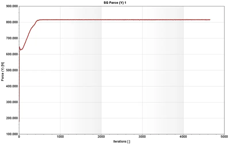
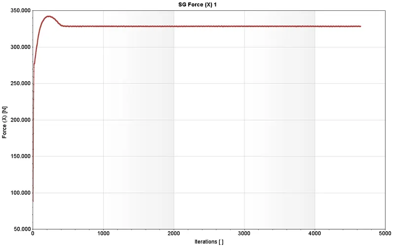
- Lift and Drag force plotting (Insert -> Goal plot ->SG force(X) and SG force(Y))
- Results
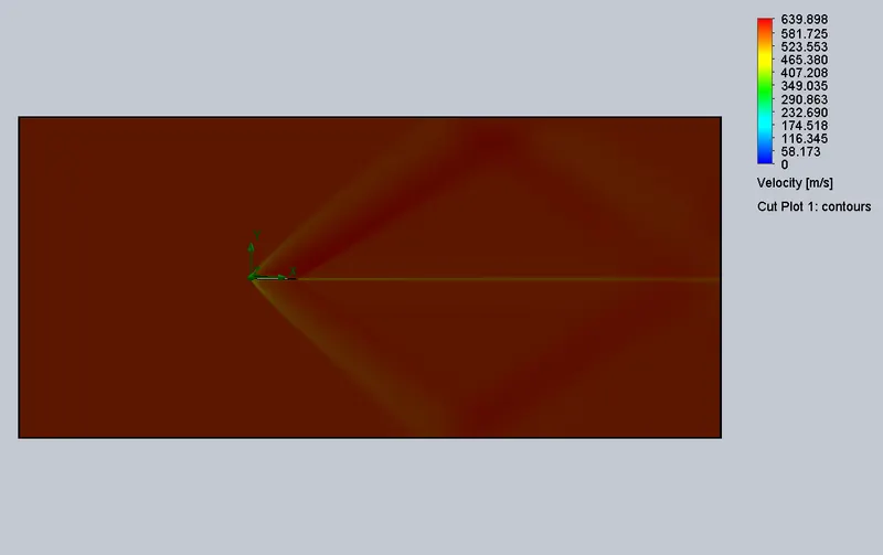
- Cutplots (Results -> Cutplots ->XY plane -> Velocity)
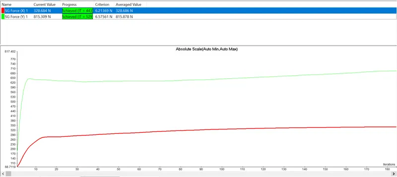
- Lift and Drag force values (Results -> Goal -> Insert -> SG force(X) and SG force(Y) ->show)
RESULTS
- AOA - 0
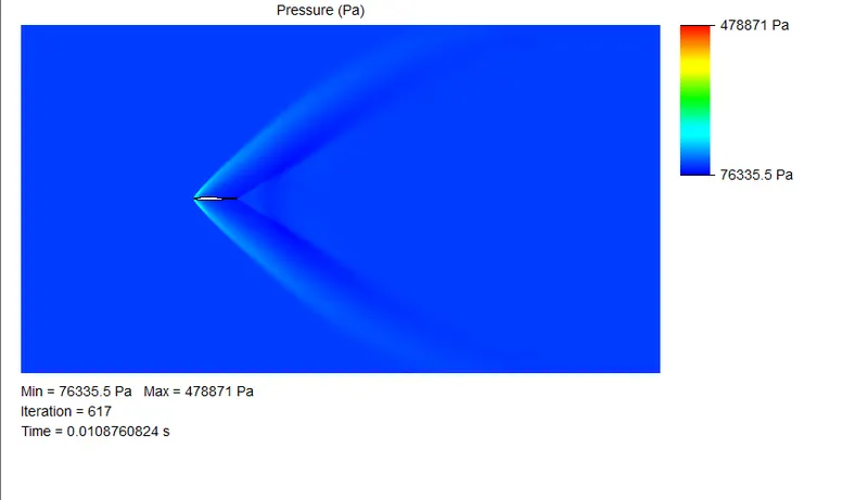
Pressure
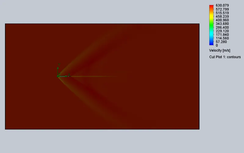
Velocity
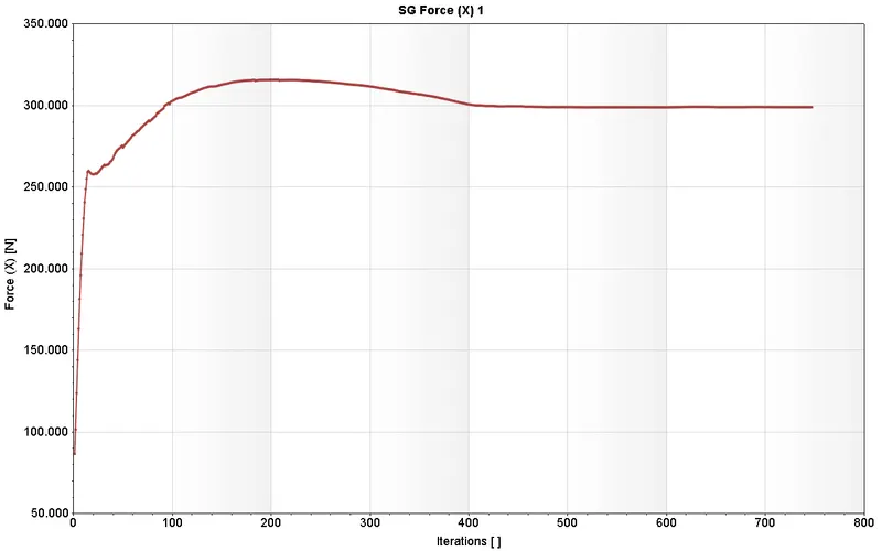
Lift and Drag
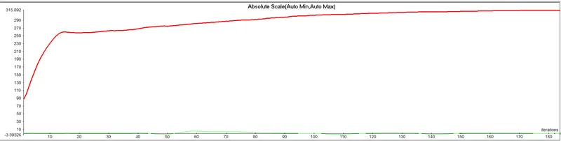

Lift
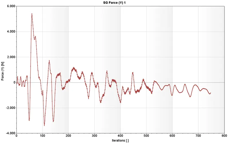
Drag
- AOA - 2
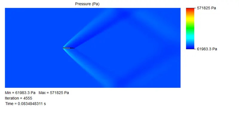
Pressure
Velocity
Lift and Drag

Lift
Drag
- AOA - 4
Pressure
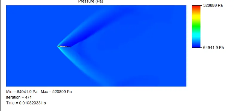
Velocity
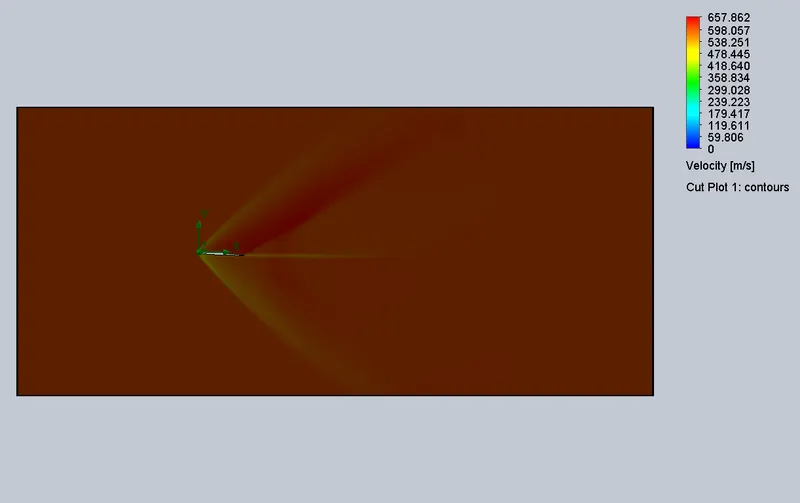
Lift and Drag
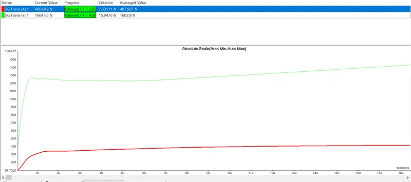

Lift
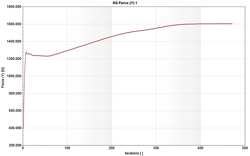
Drag
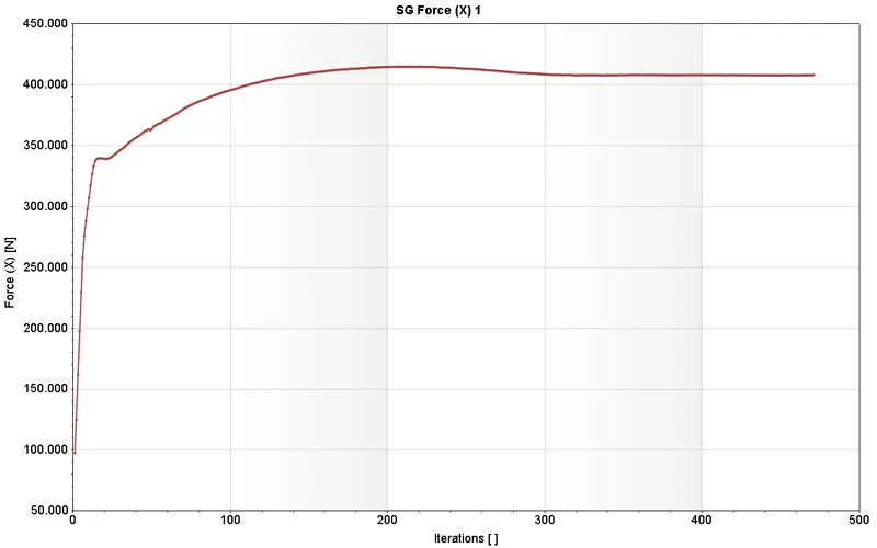
- AOA - 6
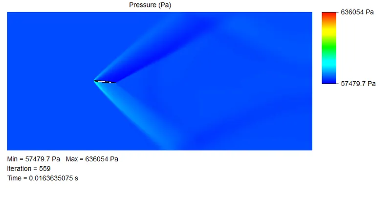
Pressure
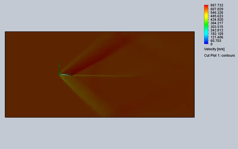
Velocity
Lift and Drag
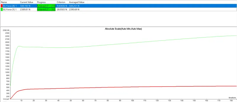

Lift
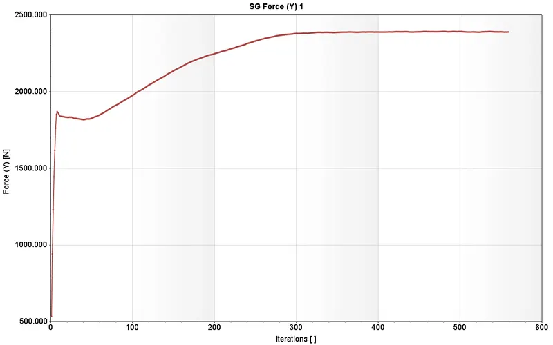
Drag
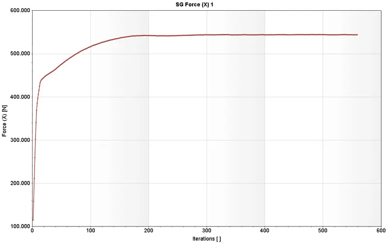
- AOA - 8
Pressure
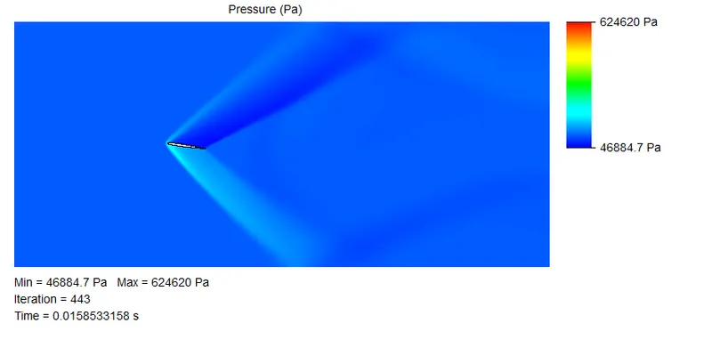
Velocity
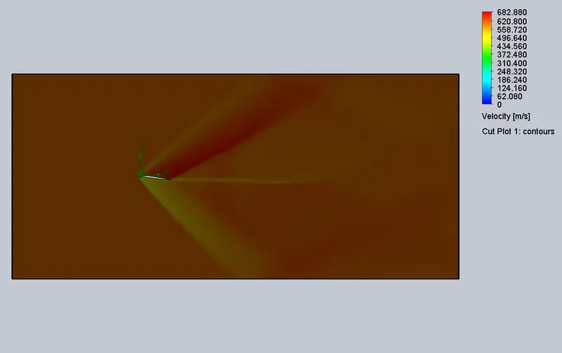
Lift and Drag
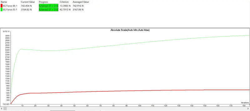

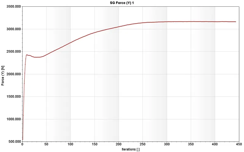
Lift
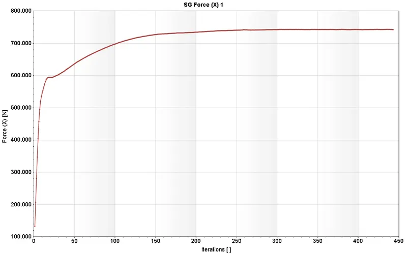
Drag
- AOA - 10
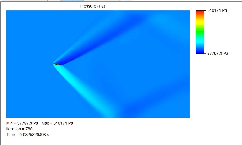
Pressure
Velocity
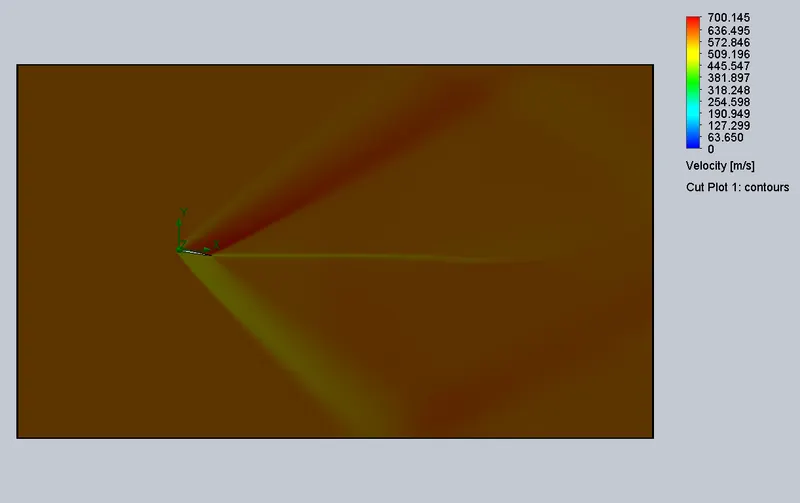
Lift and Drag
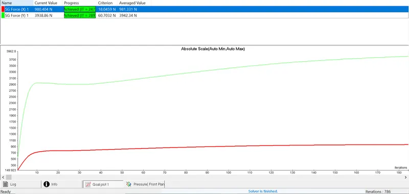

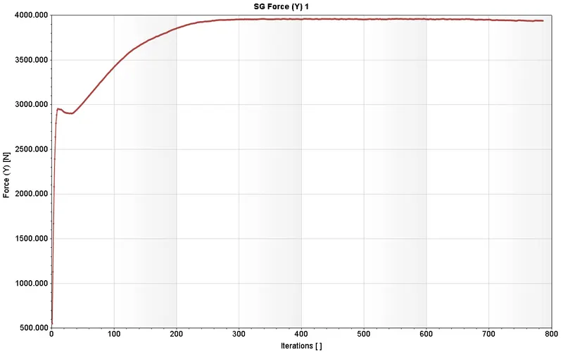
Lift
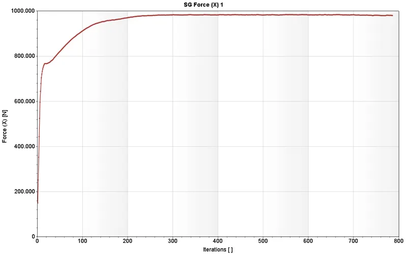
Drag
CONCLUSION
An increase in angle of attack results in an increase in both lift and induced drag, up to a point. Too high an angle of attack (usually around 17 degrees) and the airflow across the upper surface of the aerofoil becomes detached, resulting in a loss of lift, otherwise known as a Stall.