Flow over Ahmed body with Spoiler
Objective:
- Change in coefficient of drag and lift with change in spoiler angle.
Introduction:
- Fuel consumption and High speeds are two of the major concerns of automobile makers.
- Aerodynamics plays a major role in solving the above two problems.
- Force exerted by a flowing fluid on a stationary object can be divided into two components.
- Drag force: Component of force in the direction of motion.
- Lift force: Component of force perpendicular the direction of motion.
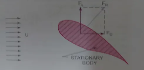
- Drag force is further governed by Friction and Pressure drag. For different types of bodies, one of the two dominates.
- Streamlined body: Body whose surface coincides with the streamlines, when the body is placed in a flow. Separation of flow takes place at its trailing edge.
- Bluff body: Body whose surface does not coincides with the streamlines, when the body is placed in a flow. Separation of flow takes place much ahead of its trailing edge.
- Drag force(Fd)= (Cd*(density)*(area)*(velocity^2))/2
- Drag coefficient(Cd) plays a major role here.
- Lift force is created due to negative pressure created on the upper part of the airfoil. Streamlined body.
- Lift force(Fl)= (Cl*(density)*(area)*(velocity^2))/2
- Lift coefficient(Cl) plays a major role here.
Spoiler:
- Spoiler shape is same as airfoil but the trailing edge is as shown.
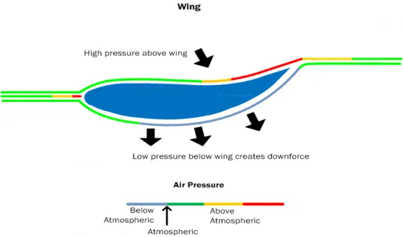
- Spoiler is added to provide more down force. So it is opposite to lift force. This increases the stability of the car.
- In case of an airfoil, Velocity above the airfoil is more as compared to down, therefore pressure below the airfoil is more as compared to above, hence lift is observed.
- In case of a spoiler, Velocity above the spoiler is less as compared to down, therefore pressure above the airfoil is more as compared to below, hence negative lift or down force is observed.
- Hence with addition of spoiler, Lift coefficient decreases.
Geometry:
- Design a rear spoiler at different angles(-15 degree to 15 degrees).
- Prepare an outer enclosure for base geometry.
- Prepare an inner enclosure depending upon the wake zone size.
- Use split body to split the final geometry into half to refine mesh in student version.
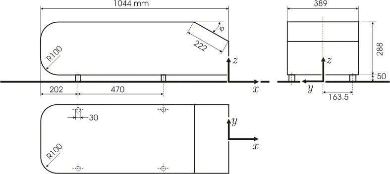
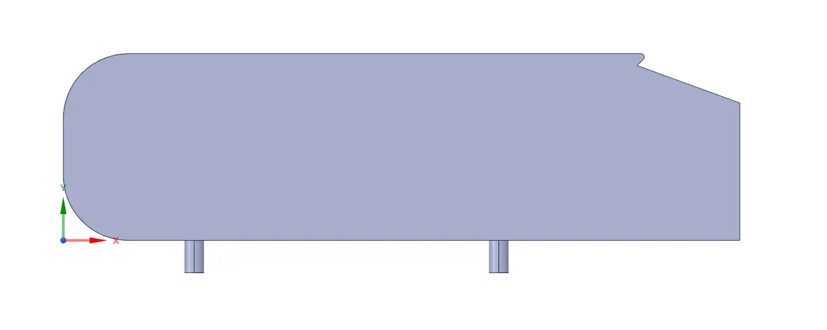
Figure-1 Ahmed body with rear spoiler
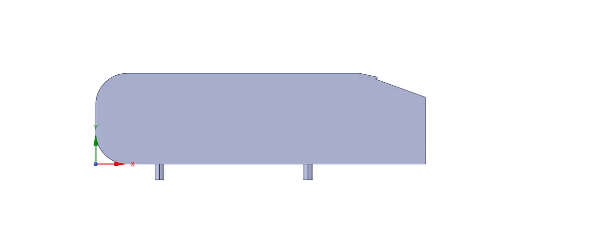
Figure-2 Ahmed body with low angle rear spoiler
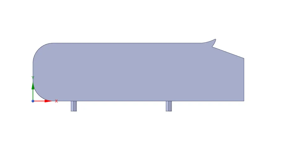
Figure-3 Ahmed body with high angle rear spoiler
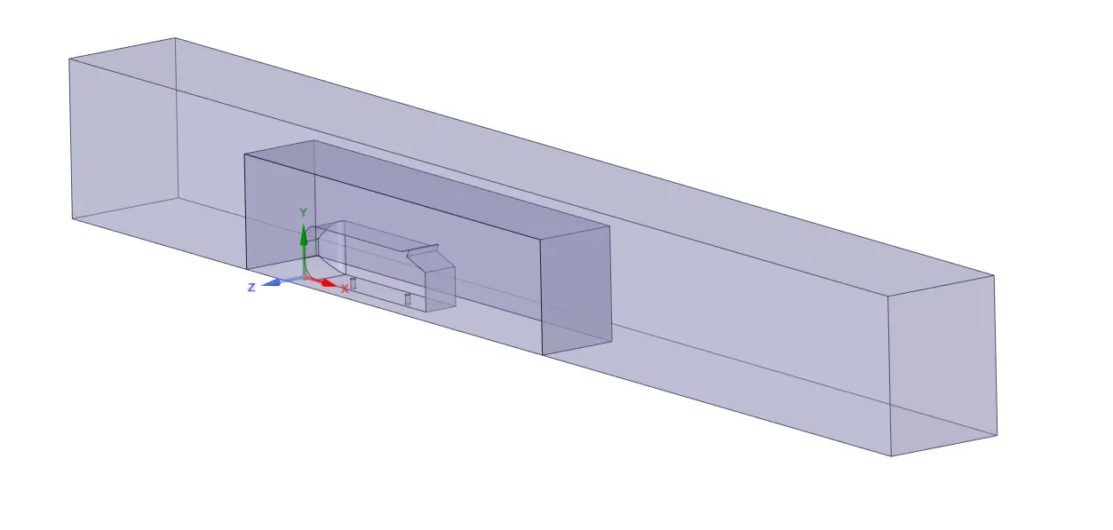
Figure-4 Final geometry
Mesh:
- Use Hexa elements for outer enclosure for better accuracy.
- Inflation layer is introduced around Ahmed body to capture lift and drag coefficient accurately. Total thickness of 7.952 mm is given using Y+ value of 50.

Figure-5 Basic mesh
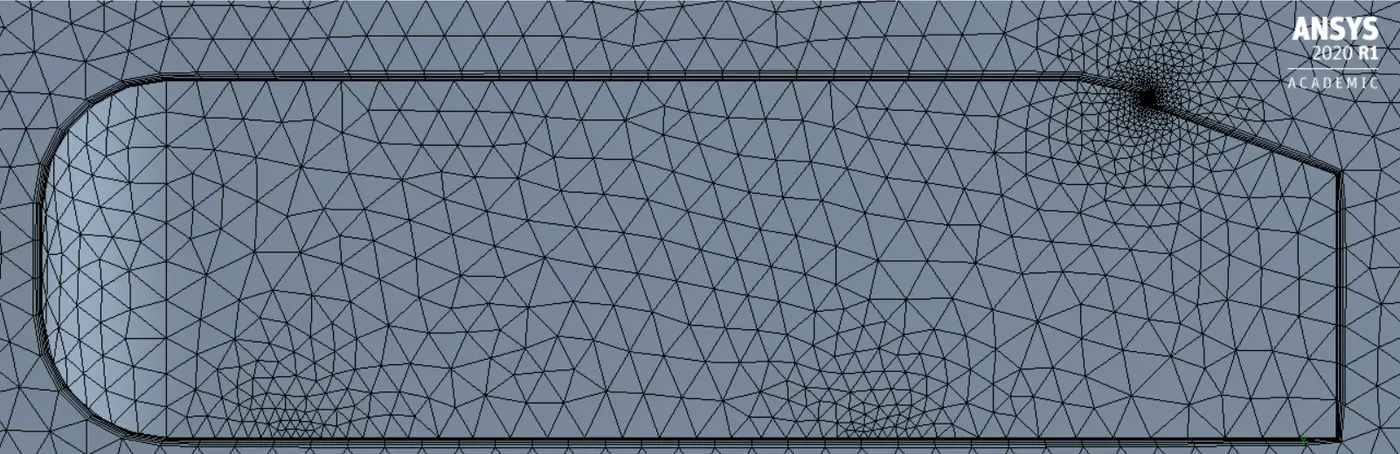
Figure-6 Inflation layer
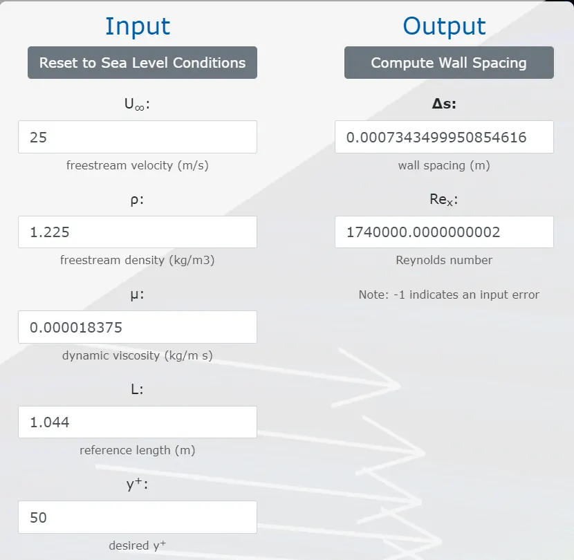
Figure-7 Spacing between layers
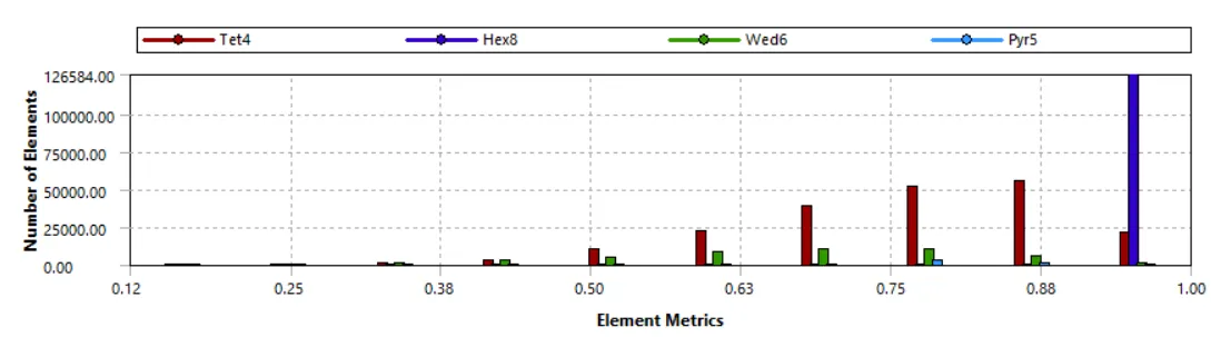
Mesh Quality
Setup:
- Pressure based solver is used. Steady flow and absolute velocity is taken.
- K-epsilon, Standard wall functions model is taken.
- Air is taken as the working fluid.
- Inlet velocity of air is taken as 25m/s.
- Reference values: Area=0.055 m^2, Length=1.044, Velocity=25 m/s.
- Hybrid Initialization is done and solution is run for 350 iterations.
- Coefficient of drag and lift are calculated at car wall.
Case-1 Spoiler angle: 0 degrees
- Cd=0.467
- Cl=0.304
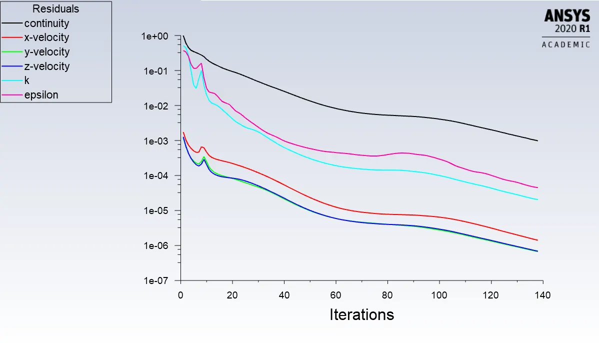
Figure-8 Residual
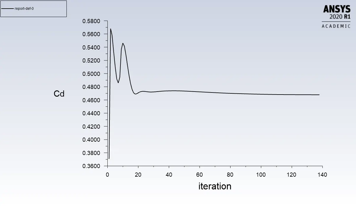
Figure-9 Cd plot
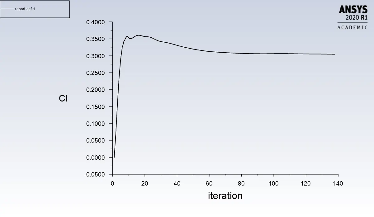
Figure-10 Cl plot
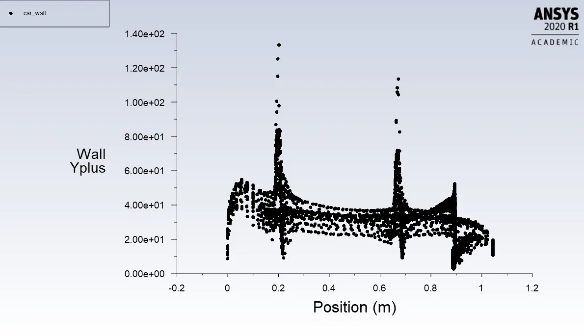
Figure-11 Y plus plot
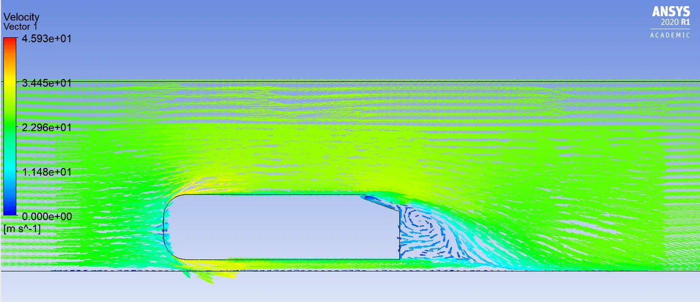
Figure-12 Velocity vectors
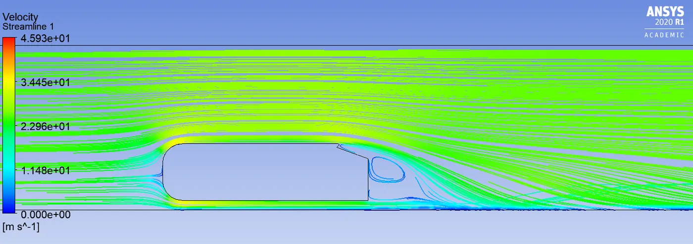
Figure-13 Streamlines
Case-2 Spoiler angle: -15 degrees
- Cd=0.432
- Cl=0.357
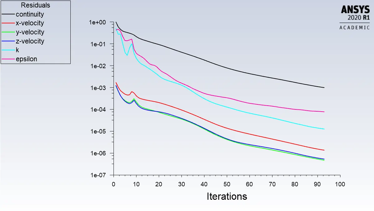
Figure-14 Residual
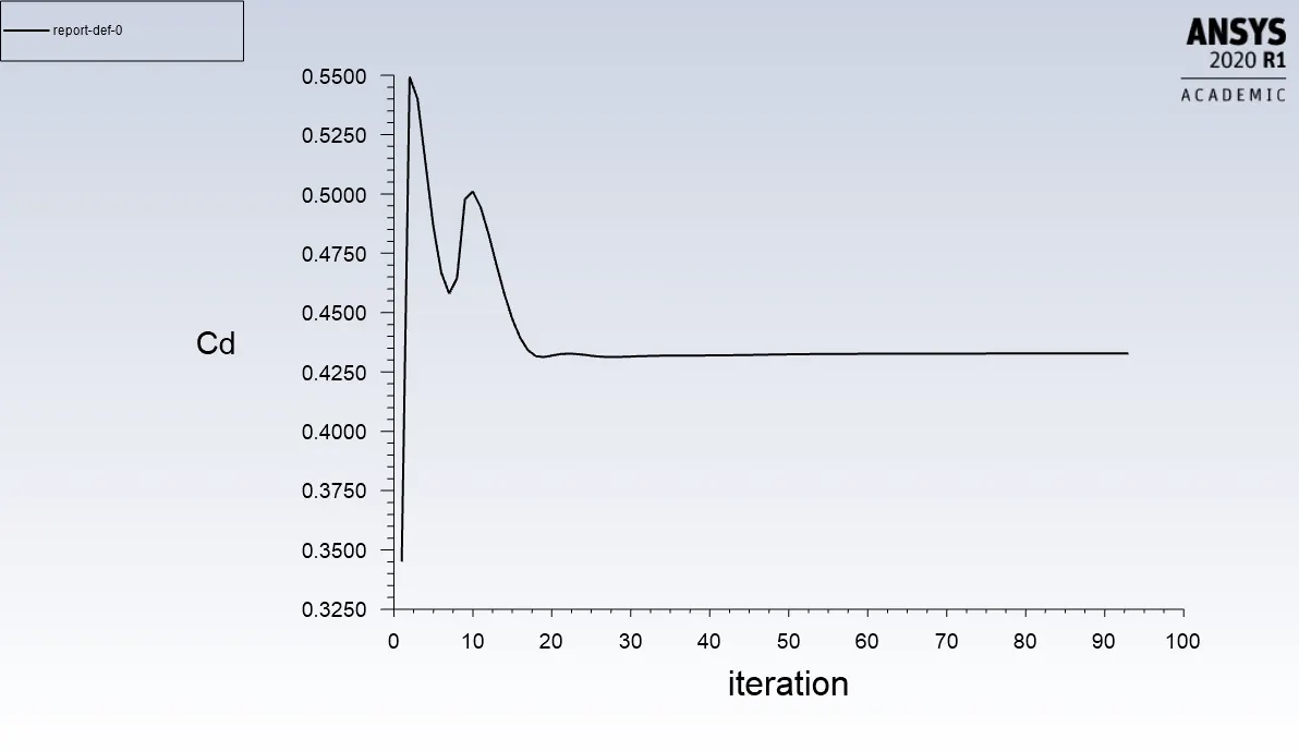
Figure-15 Cd plot
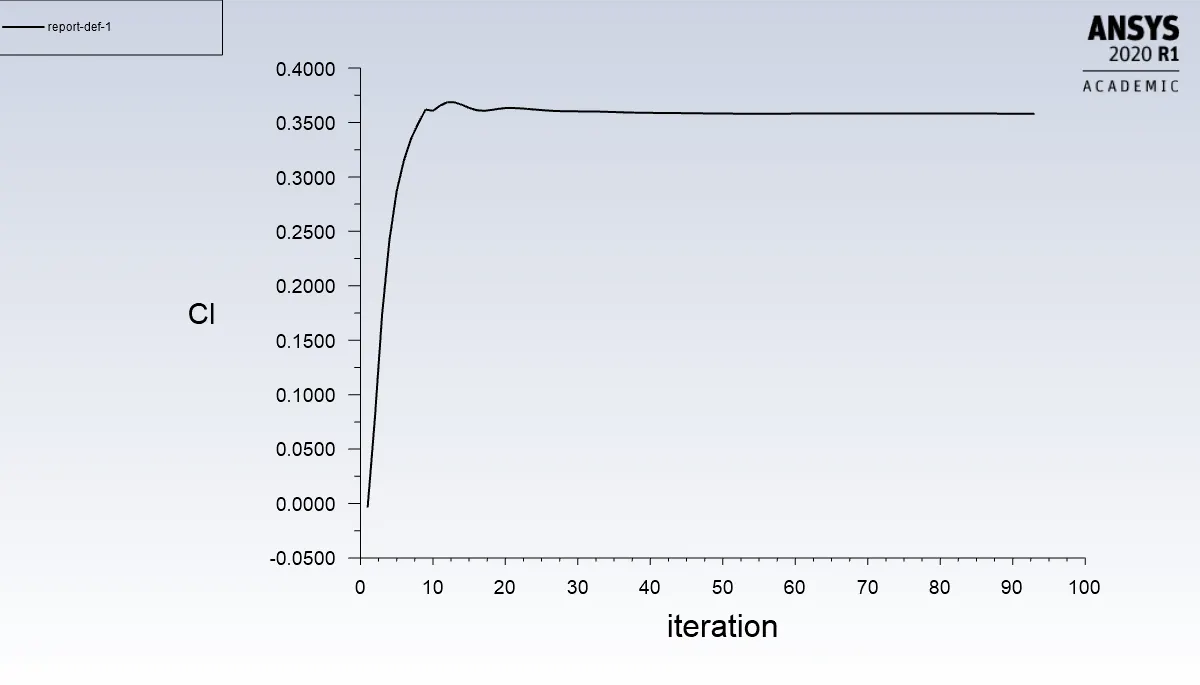
Figure-16 Cl plot
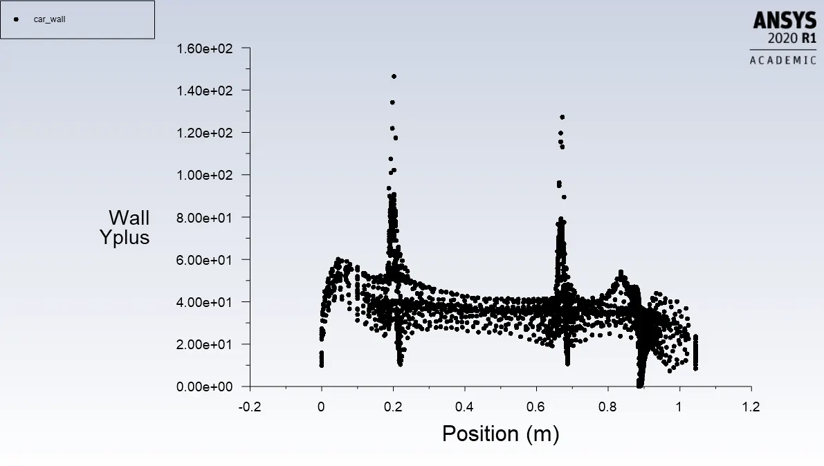
Figure-17 Y plus
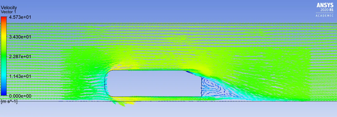
Figure-18 Velocity vectors
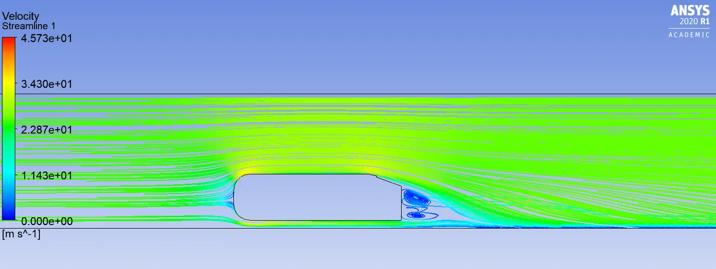
Figure-19 Streamlines
Case-3 Spoiler angle: 15 degrees
- Cd=0.519
- Cl=-0.136
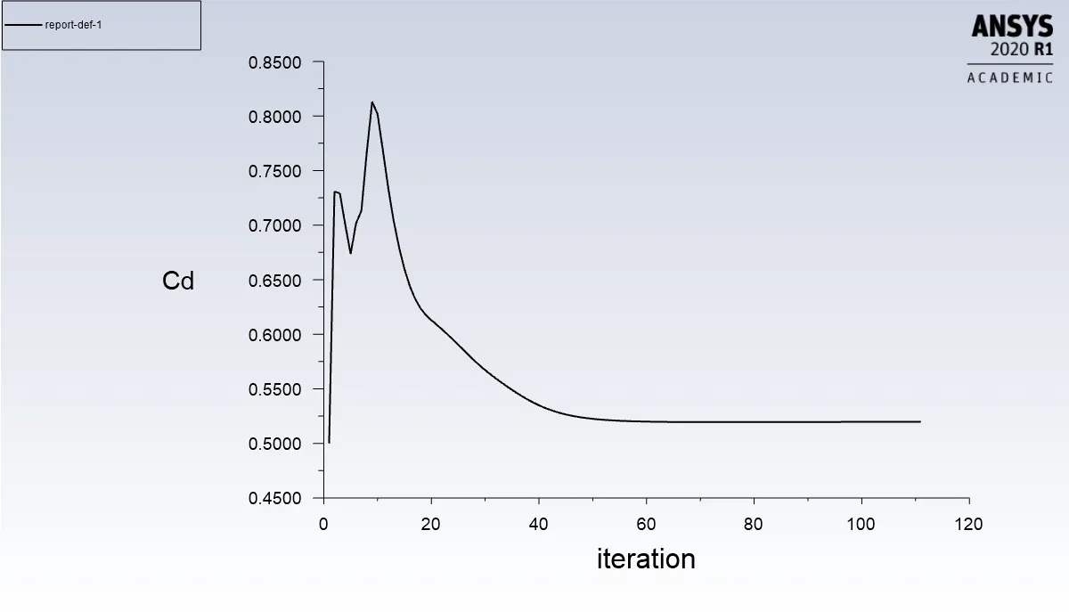
Figure-20 Cd plot
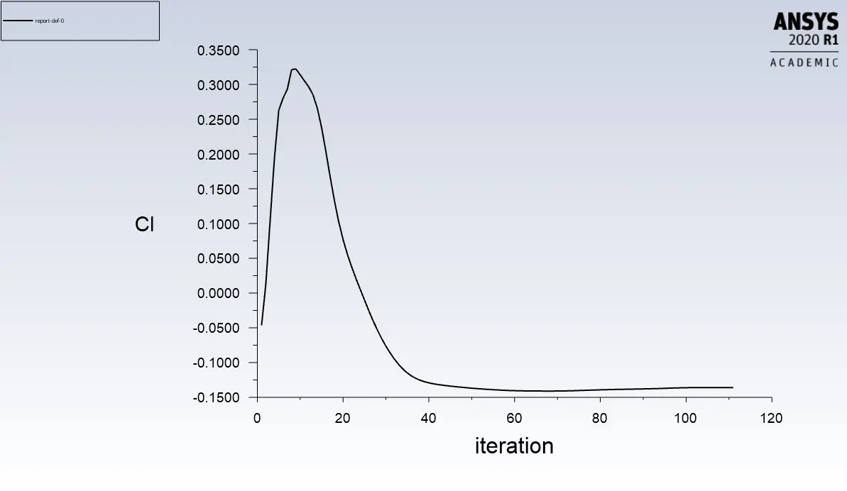
Figure-21 Cl plot
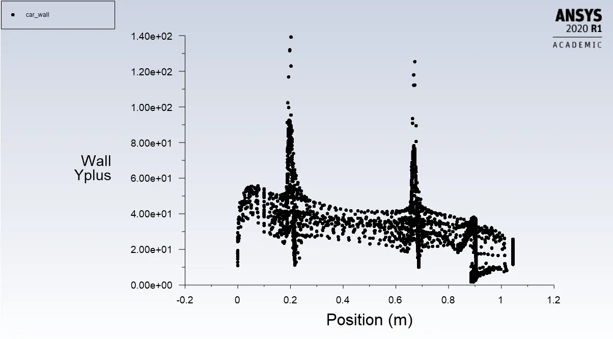
Figure-22 Y plus
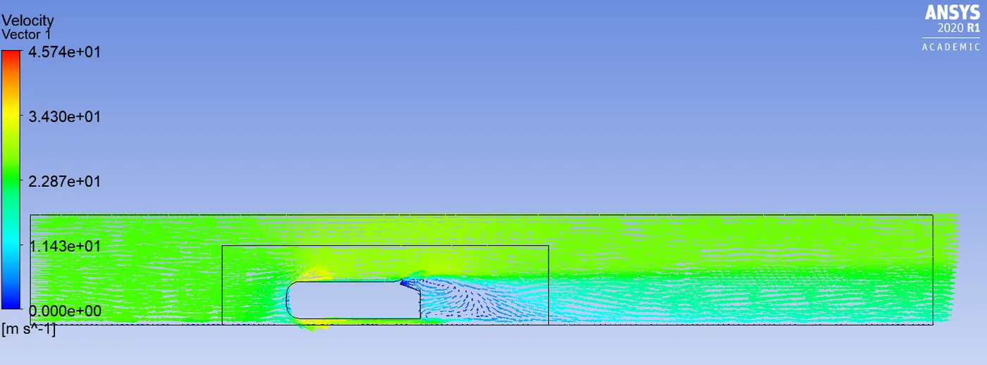
Figure-23 Velocity vectors
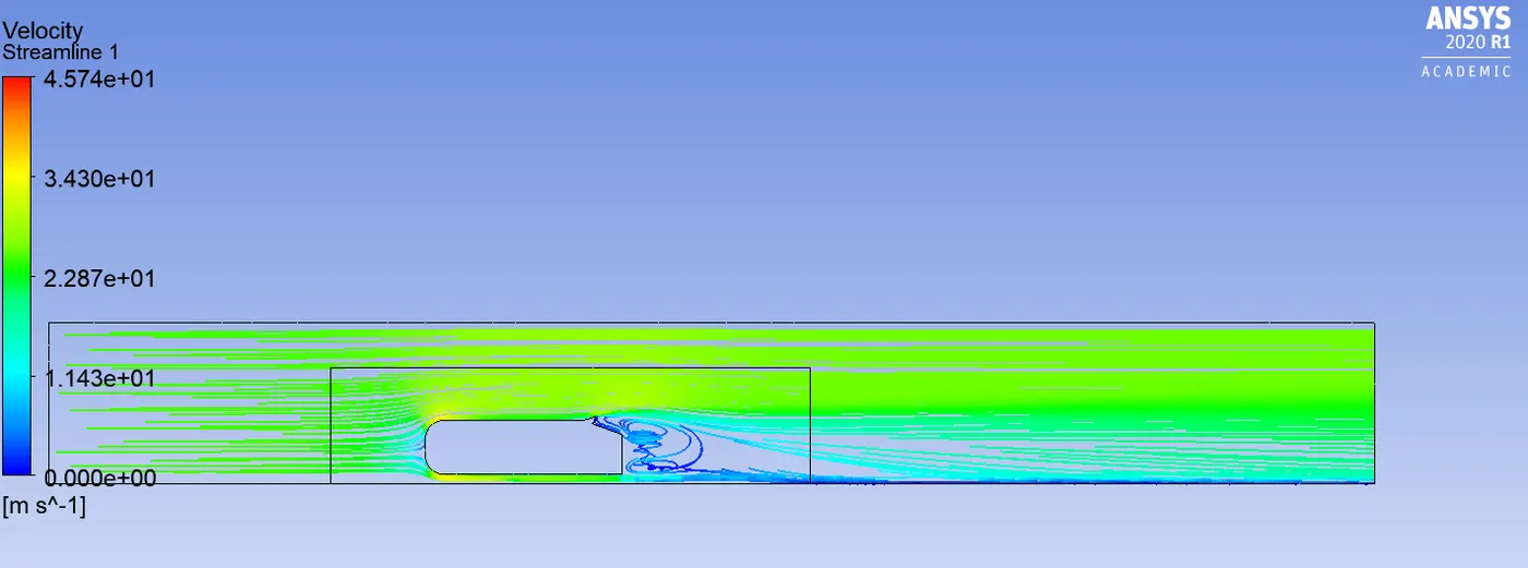
Figure-24 Streamlines
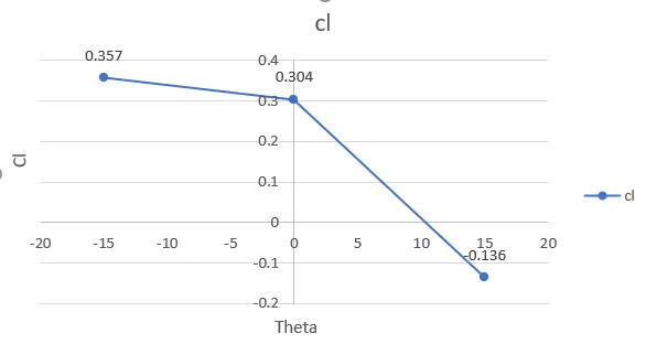
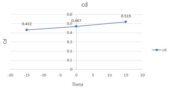
Figure-25 Cd and Cl vs Theta
Conclusion:
- Aerodynamic lift (Cl) decreases nearly linearly with the inclination angle of the spoiler.
- Aerodynamic drag (Cd) increases with the inclination angle of the spoiler.
- To avoid the formation of vortices Louvers are added with plate end cuts. These create vortices in opposite direction and hence reduces drag.