FINAL TEST
PORT FUEL INJECTION:
1. What is the Compression ratio for the engine?
The compression ratio is the ratio between the volume of the cylinder and combustion chamber in an internal combustion engine at their maximum and minimum values.
In a piston engine, the static compression ratio(CR) is the ratio between the volume of the cylinder and combustion chamber when the piston is at the bottom of its stroke, and the volume of the combustion chamber when the piston is at the top of its stroke.
`CR = (V_s + V_c)/V_c`
where,
- `V_s`= swept volume. This is the volume inside the cylinder displaced by the piston from the beginning of the compression stroke to the end of the stroke.
- `V_c` = clearance volume. This is the volume of the space in the cylinder left at the end of the compression stroke.
- `V_s`can be estimated by the cylinder volume formula
- `V_s = pi/4*d^2*L`
Where:
- d = cylinder bore (diameter)
- L = piston stroke length
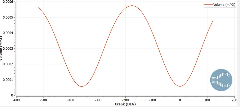
Maximum volume = `0.00057 m^3`
Minimum volume = `5.75*10^(-5) m^3`
Compression Ratio (CR) = Maximum volume / Minimum volume
= 0.00057 / `5.75*10^(-5) m^3`
CR = 10:1
2. Modify the compression ratio for this engine to 10.3 without changing geometrical parameters?
To modify the compression ratio of the engine without changing its geometrical parameters, either the clearance volume (or) swept volume should be changed.
METHOD 1: swept volume is constant and clearance volume is varied.
`V_(max) => V_c + V_s => 0.00057 m^3`
`V_min => V_c => 5.75*10^(-5) m^3`
`V_s = V_(max) - V_c => 0.00057 - 5.75*10^(-5) => 5.125*10^(-4) m^3`
`CR = (V_s + V_c)/V_c`
`10.3 = (5.125*10^(-4) + V_c)/V_c`
`V_c = 5.5107 * 10^(-5) m^3`
Thus, the required compression ratio 10.3 can be achieved by changing the clearance volume to 5.5107 * 10-5 m3 while keeping swept volume as constant.
METHOD 2: clearance volume is constant and swept volume is varied.
`CR = (V_s + V_c)/V_c`
`10.3 = (5.75*10^(-5) + V_s) / 5.75*10^(-5)`
`V_s = 5.3475*10^(-4) m^3`
Hence, to get the required compression ratio 10.3, the swept volume is changed to 5.3475*10-4 m3 by changing the bore (or) stroke length of the engine by keeping the clearance volume as constant.
3. Calculate Volumetric Efficiency for this engine?
Volumetric efficiency (VE) in internal combustion engine engineering is defined as the ratio of the mass density of the air-fuel mixture drawn into the cylinder at atmospheric pressure (during the intake stroke) to the mass density of the same volume of air in the intake manifold.
`text(Volumetric Efficiency) = V_a / V_s *100`
We know that swept volume `V_s = 5.125*10^(-4) m3`
Assume the air used is ideal in nature. Therefore using the ideal gas equation,
P * Va = m * R * T
Va = (m * R * T) / P
where,
P – Pressure of air at atmospheric condition (101325 N/m2)
m – Mass of air
R – Universal gas constant (287 J/Kg-K)
T – Temperature of air at atmospheric condition (293 K)
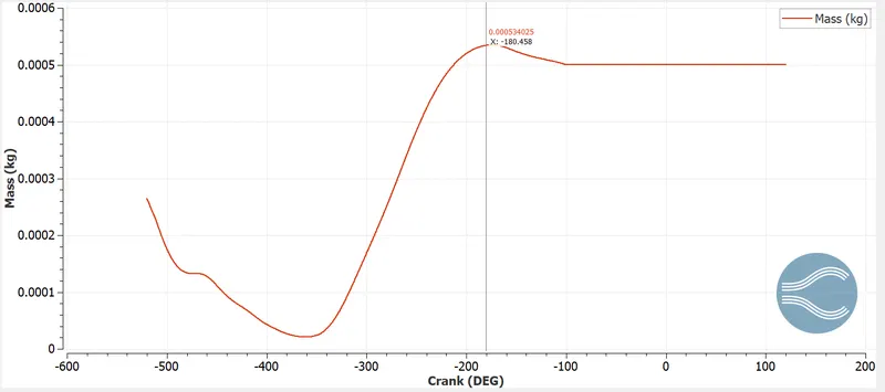
Mass is taken from the above plot as m = 0.000534 kg
Va = [(0.000534 * 287 * 293)] / 101325
Va = 4.4317 * 10-4 m3
Volumetric Efficiency = (4.4317 * 10-4) / (5.125*10-4) * 100
Volumetric Efficiency = 86.47 %
4. Measure the air mass flow rate for this engine in kg/s?
The mass of air (m) is taken as 0.000534 Kg.
This mass is the mass flow rate of air into the cylinder per 360 degree.
Speed of the engine (N) = 3000 rpm = 3000 / 60 = 50 rps.
Angle covered in one second = 50 * 360 = 18000 degrees.
Mass of air entering for 18000 degrees = 0.000858711 * 50 = 0.0267 Kg/s.
ṁa = 0.0267 Kg/s
5. Why is the cell count varying during the simulation?
The cell count is varying during the simulation because of the Adaptive Mesh Refinement(AMR) and Fixed embedding used to capture the physics accurately in critical areas.
The velocity and temperature AMR are used in PFI engine.
For example in velocity AMR if we set SGS as 1m/s then above it cell will become finer by a factor of 2^n here n is embed level if it is 2 mesh becomes finer by 2^2 is 4 times.
6. In a real engine, valves are in contact with the cylinder head but while running simulation, there is a small gap?
- WHY?
- What happens if this gap is big?
WHY?
In real engines, the valves are in contact with the cylinder head to avoid escaping of fuels and heat from the combustion chamber. The movement of valves are controled by using cam and follower mechanism.
In our PFI simulation we have not designed any mechanism to drive the valves. So there is small gap between cylinder head and valve. During the simulation, converge automatically creates disconnect triangles between the gap.
What happens if this gap is big?
when this gap is big, the heat dissipation between cylinder head and cylinder wall cannot take place. This increases the temperature in the cylinder which can lead to problems like detonation (or) knocking and it can also increase the emission like NOx, unwanted HC and soot which will decrease the efficiency and life of the engine.
7. How many seconds does combustion last in this case?
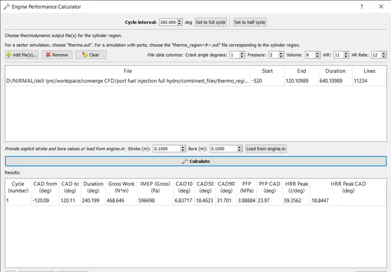
From the above plot,
Duration of combustion is 240.199 degrees.
Engine speed (N) = 3000 rpm => 50 rps
Revolution in degrees = 360*50 => 18000degrees/sec
Hence for 240.199 degrees, t = 240.199/18000
t = 0.0133 seconds
So, combustion lasts for 0.0133 seconds.
DIESEL ENGINE:
1. What is an advantage of SECTOR Simulation?
Sector simulation is a process of using only the sector of model for CFD simulation. Since size of the engine is reduced the time taken for the simulation will also reduce such that it saves computational time. As this is a closed cycle analysis the boundary conditions and parameters required to define a case is also minimum.
2. When will the sector approach not work?
The sector modelling doesnot work in case of open cycle engine analysis. In open cycle analysis, the position of walls varies with time which cannot be captured when we use sector modelling. So, sector modelling cannot be applied for open cycle analysis while it can be used for closed cycle analysis where the valves are not considered.
3. How to choose Start Crank Angle (SCA) and End Crank Angle (ECA) for a sector simulation?
The sector simulation is good incase of closed cycle analysis. So, the start crank angle can be taken at the beginning of compression stroke and the end crank angle can be taken at the end of expansion stroke.
For example if we assume the fuel to be injected at 0 degrees then 180 degree can be taken as start crank angle (SCA) and 180+360 = 540 degree can be taken as end crank angle (ECA) for diesel engine.
4. Can we convert the PFI case into a SECTOR case? Explain your answer?
PFI case is an open cycle analysis type. As i said before sector modelling is suitable only for closed cycle analysis where a closed part of 360 degree chamber can be simulated for saving computational time.
As in case of PFI the valves are considered which makes it a open cycle analysis. So the PFI case cannot be converted into a sector case.