Final Project: Electric Rickshaw modelling
Create a detailed MATLAB model of an electric rickshaw (three wheel passenger vehicle) as per details below:
Rear wheels driven by PM brushed type motor
Assume efficiency points of motor controller and motor
Make an excel sheet of all input and assumed data
Results: For any three standard driving cycles show energy consumption, temperature rise of motor and controller for 100 km constant speed driving at 45 kmph.
(Note- The simulink model file should be compulsorily attached)
Aim: To create Matlab Model of electric rickshaw using a battery and a permenant magnet brushed motor.
Theory:
Electric rickshaw is an Auto which uses electricity as Fuel. To store electricity, batteries are used. These vechicles are becoming popular due less harmful to environment and these vechicles use electricty as fuel which is cheaper in price.
In this vechicle the electric motors are used which has more than 80% efficiency due to which losses in system are very less.
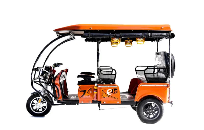
Explanation
Main components of this car are
1: Motor
2: Batteries
3: Control circuit( power converters)
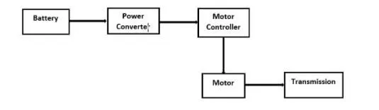
Batteries:
Batteries store electrical energy in the DC form. These are generally arranged in series or parallel.
Series arrangemet are use for increasing voltage rating and parallel arrangement are used for increasing current rating.
state of charge is generally used for representing how much charge is present in the battery at any moment.
Batteries are charged from external power supply and some times solar power is also used to charge the batteries.
Power converter and Motor Controller:
Batteries discharges a constant DC power.
Generally motor are AC as well as DC. For AC motor, inverter circuit is used to convert DC power to variable AC power.
For a DC motor Chopper circuits are used to convert fixed DC to variable DC.
These variable powers are required in order to control speed of the vechilce at any given instant of time.
From the Acceleration paddle a reference angle will generate a reference pulses. These pulese are feed to switches of power convertes . Therfore based on reference angle the output of converter is decided and hence motor speed.
Motor:
Electrical motor is used to convert electrical energy into mechincal energy. Input to the motor is from power converter. Based on power converter output motor will rotate within speed limits.
Four quadrant is possible with the power converter. Therfore motor can act as Generator at the braking time and can charge that power to batteries.
AC as well as DC motors can be used for EV application.
System level configurations and Model parameters:
Total three system level configurations has been done in this model:
1: Vechicle Body
2: DC Motor and power Converter
3: Vechicle Driver and drive cycle.
1: Vechicle Body:
It consist of 3 Blocks
1: Tire
2: Simple Gear
3: Vechicle body
1: Tire:

It has four input ports:
S: Slip value Relative to tire and surface contact
A: Reperents axile on which tires are mounted
N: Normal Force acting on tire
H: Hub, used to transmitt Trust developed by wheel to body of vechicle
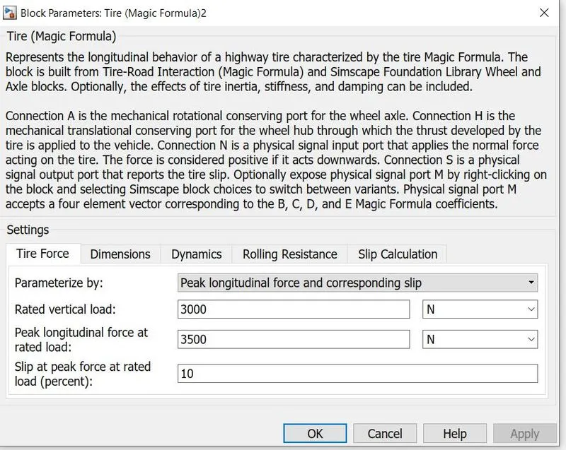
Above figure shows model parameters of a tire.
2: Simple Gear
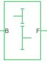
It is connected between input shaft to the base gear and output from the foller gear.
B: port associated to input shaft
F: Port assoicated to output shaft
This gear box is used to change torque speed values of motor.
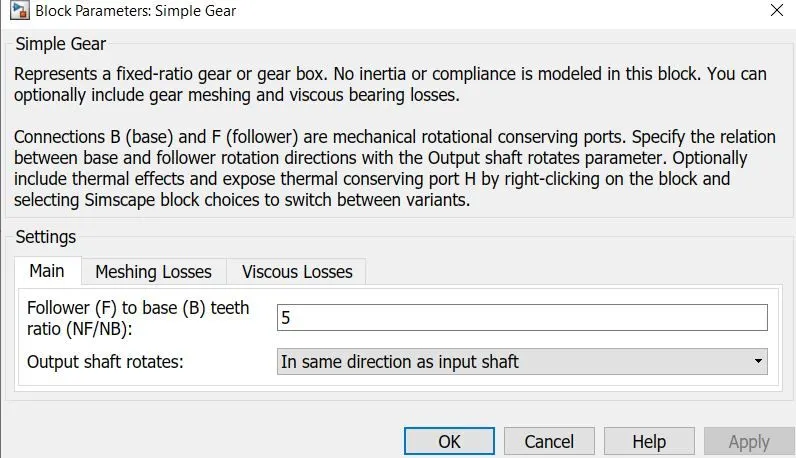
Above figure shows model parameters of a simple gear box. output shaft rotates same direction to input shaft.
3: Vechicle body
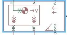
Ports of the bolck
H: Hub
V: velocity of body
W: Head wind speed
Nr, Nf: Normal reaction force on rear axile and front axile
Beta: Gradiant of the vechicle
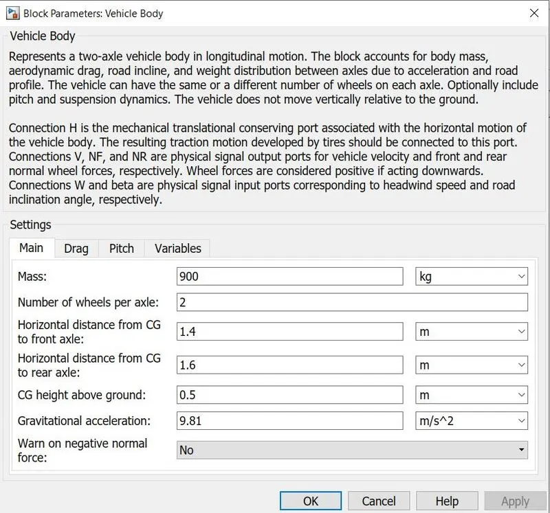
Above figure shows model parameters of a Vechile body, where mass of body is 900kgs.
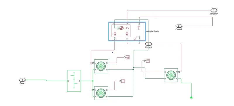
Above figure shows system level configuration of vechicle body
2: DC Motor and power Converter
It consist of
1: DC motor
2: H bridge
3: PWM
4: Battery and SOC caliculation block
1: DC motor
DC motor is used to convert electrical energy to mechanical energy. Based on H bridge input the motor will operate.
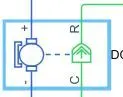
+- terminals represents input ports of DC motor. where DC voltage is applied.
C Represnts Rotor case conneceted to mechincal reference.
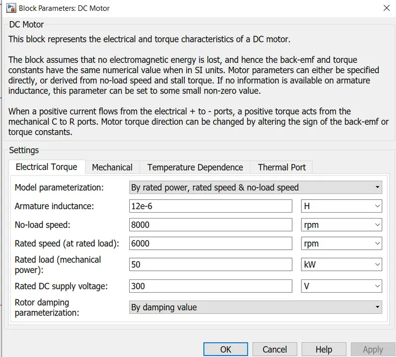
Above figure shows model para
meters of a DC motor.
2: H bridge
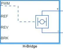
H bridge is used to convert battery DC power to variable DC motor. PWM techinque is used to drive the gate of Hbridge convereter
Ports
Pwm: For PWM input
Rev: Reverse motoring
REF: Reference
BRK : Braking input
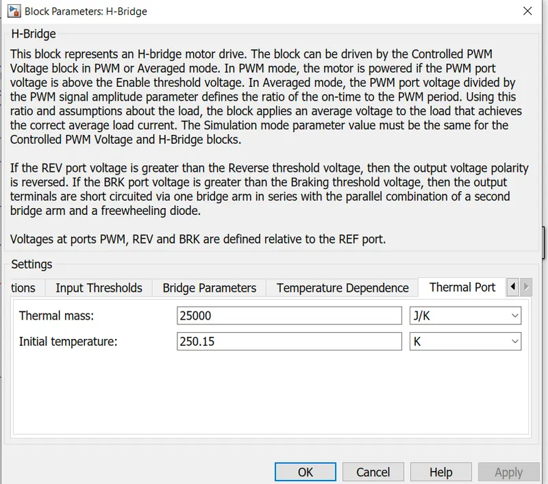
Above figure shows model parameters of a H Bridge.
3: PWM
PWM techinque is used for eliminating lower oreder hormonics from the output wave form. higher order harmonics can be eliminted using filters.

+ref is used for Acceleration
-Ref is used for Braking or decceleration
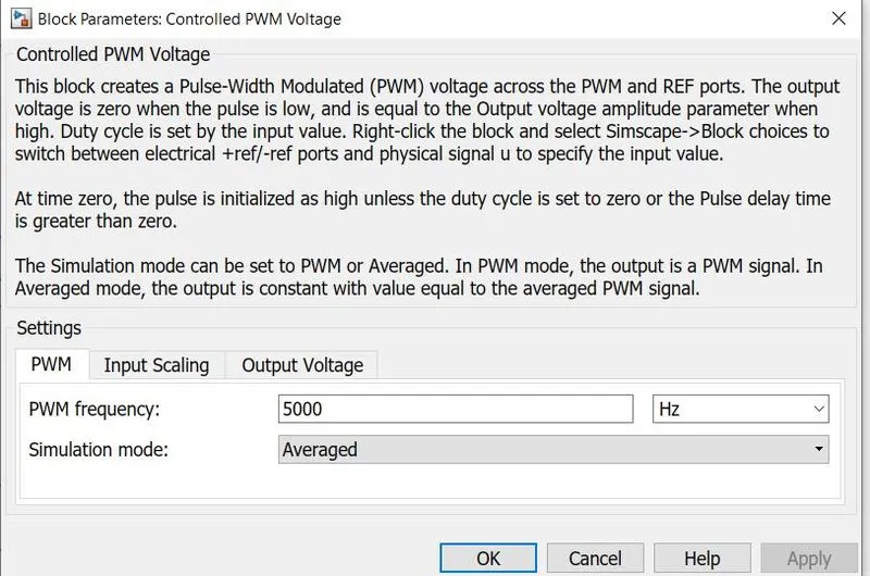
Pwm frequency is 5khz and output voltage is 300V
4: Battery and SOC caliculation block
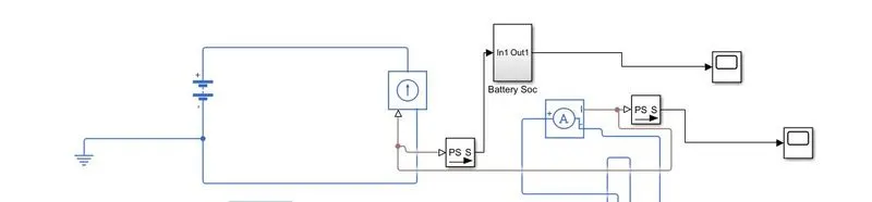
Above circuit is used to represent the battery. Input voltage of battery is 300V. To calculate actual current drawn by motor, connect Current sensor in between DC motor and H bridge.
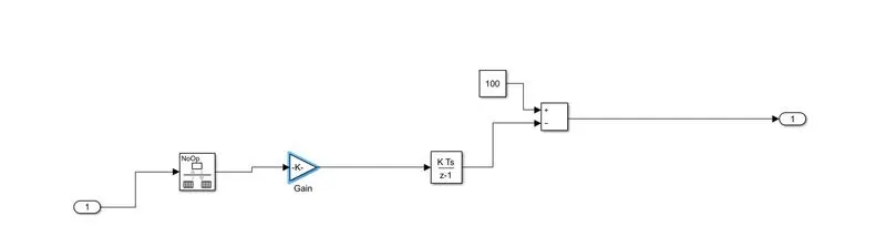
Above figure shows how to calculate soc of battery. Current drawn by motor is converted into columbs using integrator and this value is substracted from 100 percent of battery.
DC Motor and power Converter system level circuit
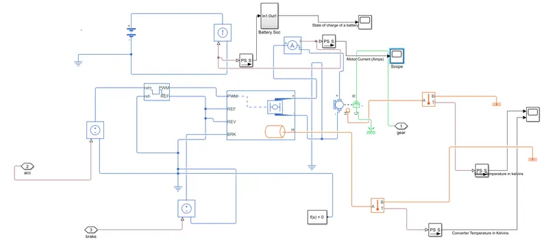
5: Vechicle Driver and drive cycle.
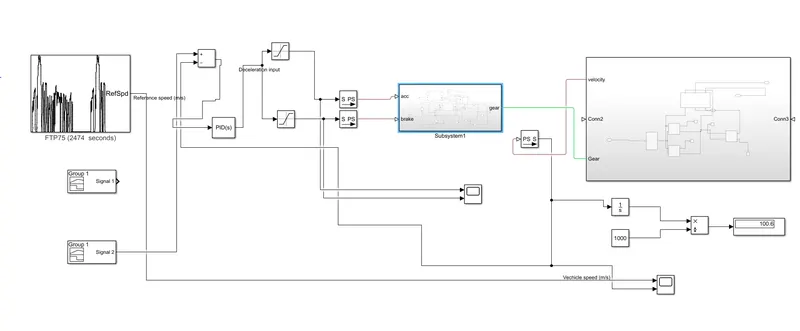
Longitudinal Driver:
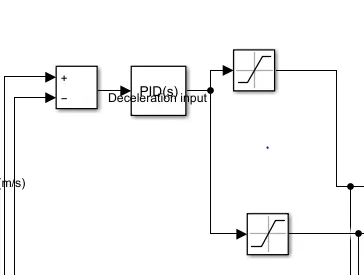
Vel Ref = this is a drive cycle input
VelFdbk= Velocity of vechicle
Based on Drive cycle input and velocity of vechicle an error is generated. Based on this error Longitudinal driver develop Acceleration comand and deceleration command.
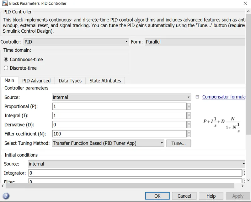
PID controller in this block used to improve the response , decrease rise time, peak time , peak overshoot. Pid controller is also helps in maintaning system stability.
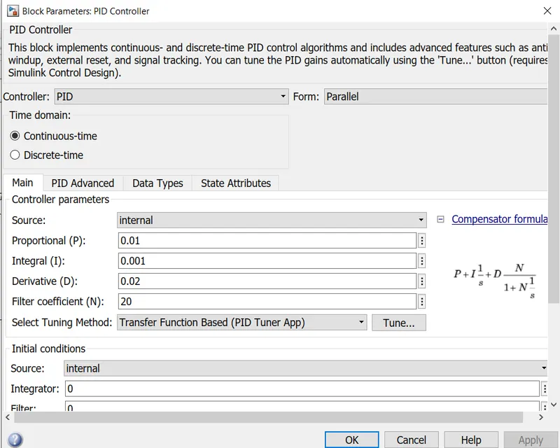
Based on trail and error method PID values are calculated.
Drive cycle:
1:FTP75 Drive cycle
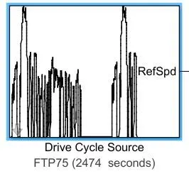
This is given as reference speed to vechicle. Based the data present in this vechicle need operate.
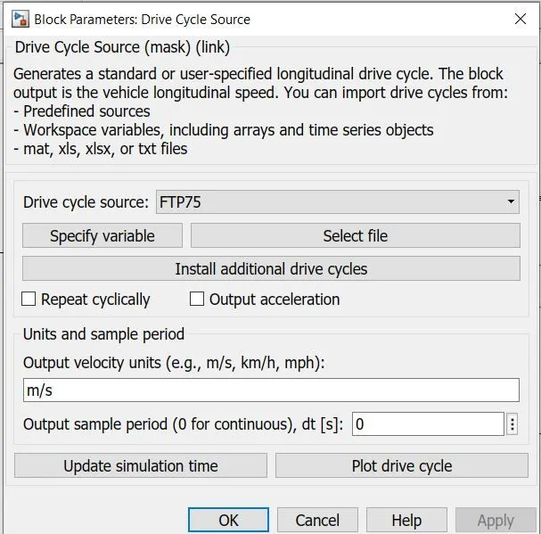
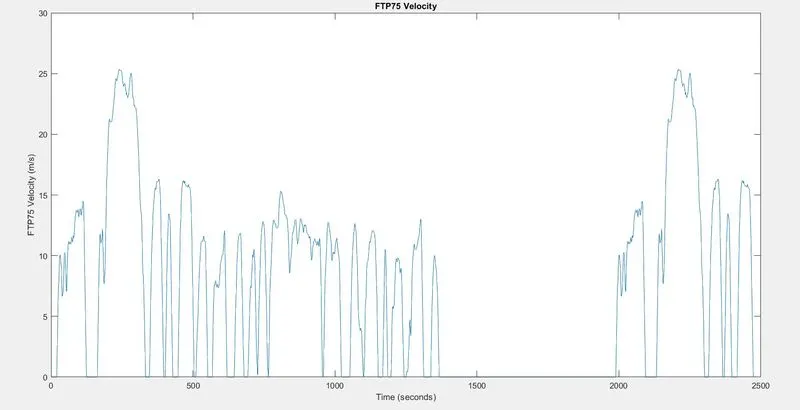
Above figure shows plot of Ftp75 drive cycle data.
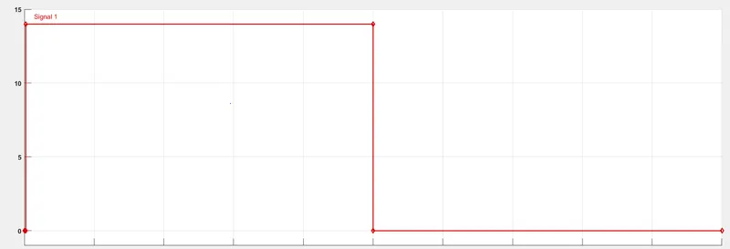
2: WOT drive cycle
3: User defined Drive cycle
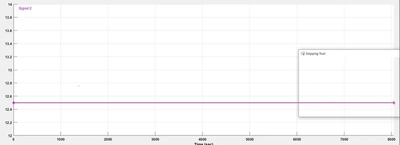
As per user the rickshaw need to travel 100Kms with a speed of 45Kmph.
By converting Kmph into m/s ,speed is converterd into 12.5m/s
speed =distance/time
12.5=100000m/time
time=8000secs
Therfore simulation time is 8000secs.
6: Temperature sensor:
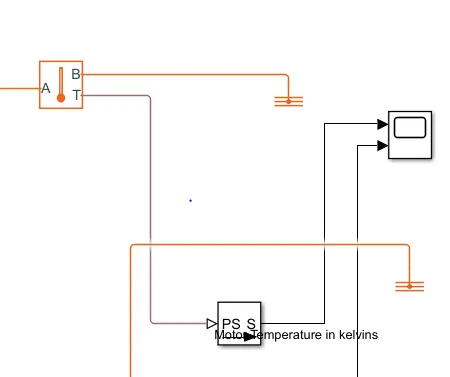
Temperature sensor will sense the temperature of motor and controller.
Simulink Model of EV
Procedure:
1 open Matlab simulink model
2:Open simulink library and browse the components
3: Connect the components as per circuit diagram
3: Simulate the results using Matlab
4: Run time for simulation is as per drive cycle.
5: Plot the results using scope
Results:
Case1: For the Ideal PID values
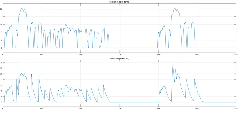
The modelled rickshaw doesnot follow the reference speed from above plot.
PID values need to be tuned using auto tuning option and plant need to be lineraized.
After linerazing following PID values are obtained.
Case2:FTP75 Drive cycle
with the tuned PID values , the model again simulated and following results are obtained.
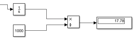
Total distance covered to run this drive cycle is 17.78kms.
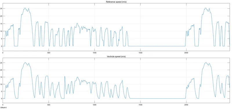
The modelled rickshaw follow the reference speed as per above plot.
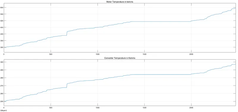
Motor temperature has risen from 300k to 600k.Temperature rise is very high, a coolent has to be introduced to control Temperature.
Controller temperature has risen from 250k to 300k.Temperature rise is within the limits.
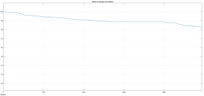
Battery state of charge is reduced to 85%.Therfore battery can run this drive cycle.
Case3: WOT drive cycle
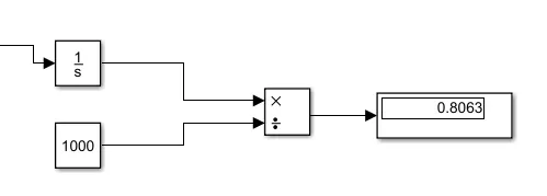
Total distance covered to run this drive cycle is 0.8063kms
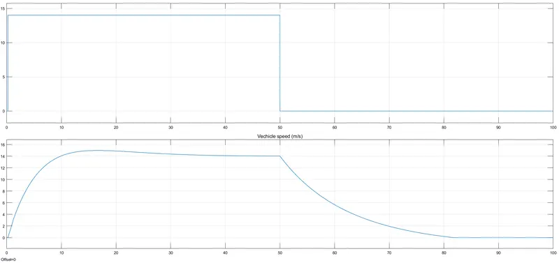
The modelled rickshaw follow the reference speed as per above plot.
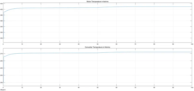
Motor temperature has risen from 300k to 400k.Temperature rise is very high, a coolent has to be introduced to control Temperature.
Controller temperature has risen from 250k to 270k.Temperature rise is within the limits.
After the drive cycle ,Temperature remains constant in model, but naturally temperature will come down.
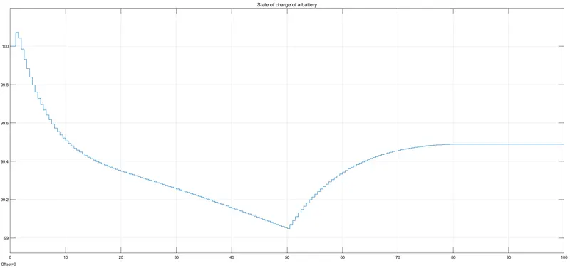
Battery state of charge is reduced to 99.2% from 100%.Therfore battery can run this drive cycle.
Case 4:User defined Drive cycle
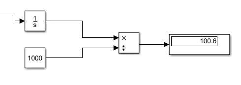
Total distance covered to run this drive cycle is 100.6kms.
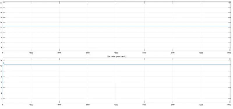
The modelled rickshaw follow the reference speed as per above plot.
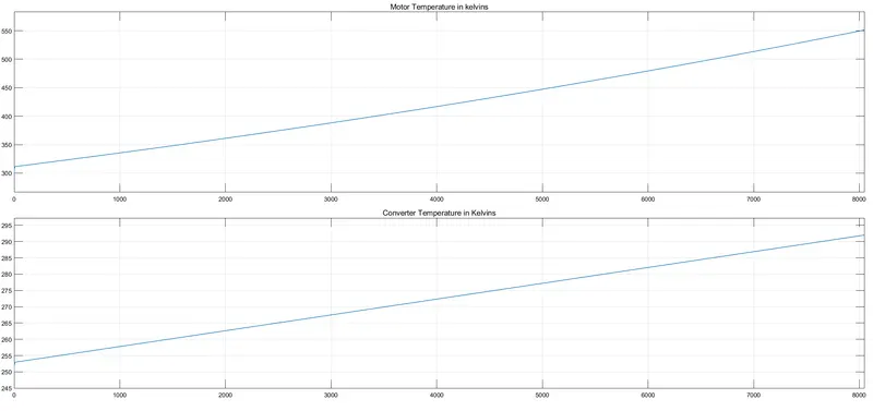
Motor temperature has risen from 300k to 550k.Temperature rise is very high, a coolent has to be introduced to control Temperature.
Controller temperature has risen from 250k to 295k.Temperature rise is within the limits.
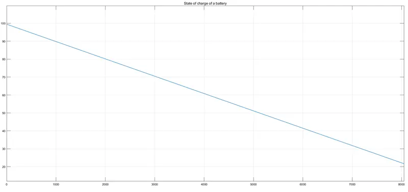
Battery state of charge is reduced to 20% from 100%.Therfore battery can run this drive cycle.
In this case battery was almost drained. Battery need to charge immediately orelse vechicle may stop.
Conclusions
1:Matlab model for electrical auto rickshaw has simulated for given drive cycle and and various Results are plotted.
2: SOC of battery has been calculated.
3: Temperature effect has been observed for all cases.
4: PID controller has improved system response.