Final Project: Electric Rickshaw modelling
OBJECTIVES:
- To Create a detailed MATLAB model of an electric rickshaw (three wheel passenger vehicle) as per details below:
- Rear wheels driven by PM brushed type motor
- Assume efficiency points of motor controller and motor
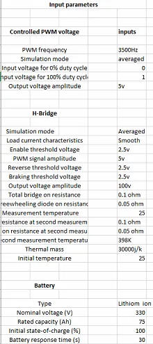
- To Make an excel sheet of all input and assumed data
- Results: For any three standard driving cycles show energy consumption, temperature rise of motor and controller for 100 km constant speed driving at 45 kmph.
MODEL OF ELECTRICAL RICKSHAW:
DRIVE CYCLE INPUT:
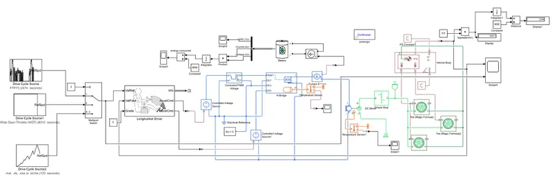
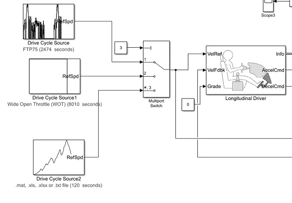
This the input system for the model. There are three different drive cycles which ic connected to multiport switch and the constant is also connected to the switch. Then the drive cycle is reference is given as input to longitudinal driver and the grade value is set to zero. The info of the longitudinal driver is terminated using terminator block. Then input for controlled voltage source is given form the output of longitudinal driver.
FTP:
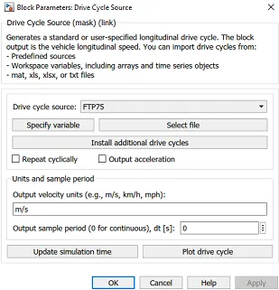
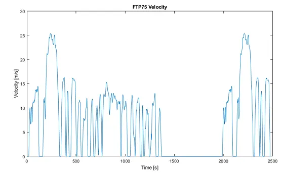
This drive cycle is default cycle which is present in matlab and the stimulation time for this drive cycle is 2474 seconds
WIDE OPEN THROTTLE:
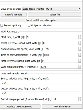
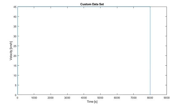
This is wide open throttle drive cycle in which vehicle runs at a constant speed of 45km/hr for a distance of 100km. Son the stimulation time for this drive cycle is 8010 seconds
CUSTOM DRIVE CYCLE:
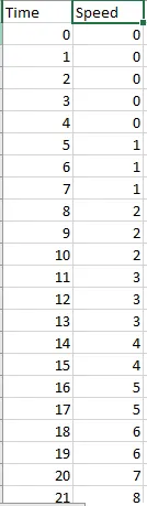
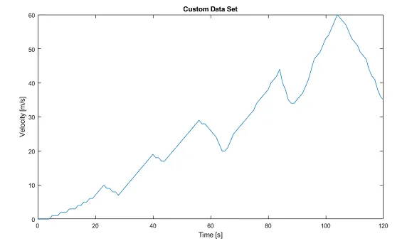
This is the custom drive cycle made in excel sheet. The run time for this drive cycle is 120 seconds.
MULTIPORT SWITCH:
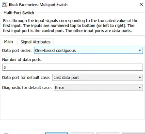
This is the switch which is used to switch between different types of drive cycle input. In this switch a constant will be connected, so if we want to change between the drive cycles the value of constant block is changed so it will switch to that drive cycle input.
CONTROL SYSTEM:
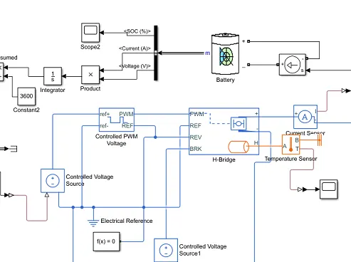
The control system of the vehicle constists of blocks like Controlled PWM voltage block, H-bridge block, Controlled voltage source block, electical reference, battery, temperature sensor, PS-simulink converter, scope. Here the output from longitudinal driver block is connected to controlled voltage source which send the input for PWM voltage block and also for H-bridge block. The output from PWM block is connected to H-bridge block, and the current sensor is connected with battery and h-bridge. From battery output we can see the SOC of vehicle and energy consumed by vehicle.
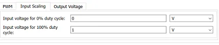
Inputs for Controlled PWM voltage:
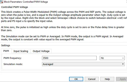
Here the PWM frequency in set to 3500hz and the simulation mode is averaged

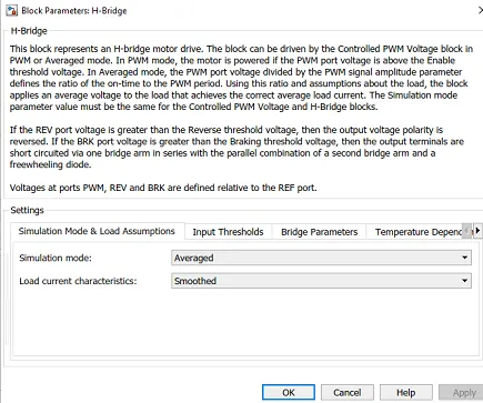
Inputs for H-Bridge block:
Here the simulation is mode is set to averaged and the load current is set to smoothed.
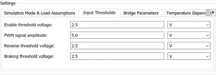
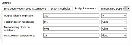
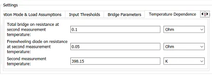
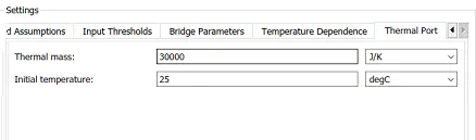
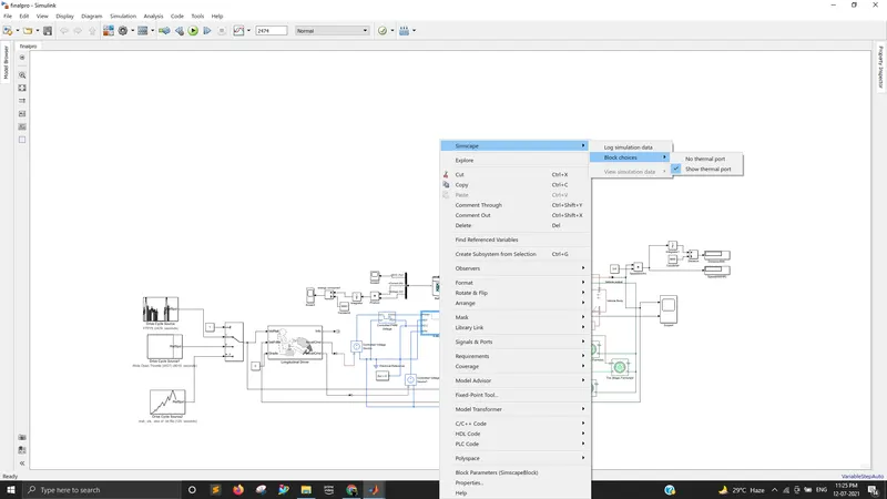
Here we have to measure temperature of controller so we have to open thermal port in H-bridge. right click on h-bridge block and choose simscape option and in that choose block choices and there select show thermal port
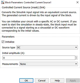
Controlled current source:
The current source is set to DC type.
Battery input:
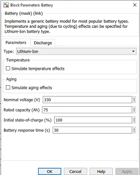
The type of battery is Lithium ion with volatage of 330v and capacity of 75Ah
Bus selector:
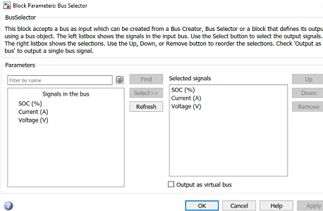
Three signals are selected from bus they are SOC, current and voltage.
DRIVETRAIN SYSTEM:
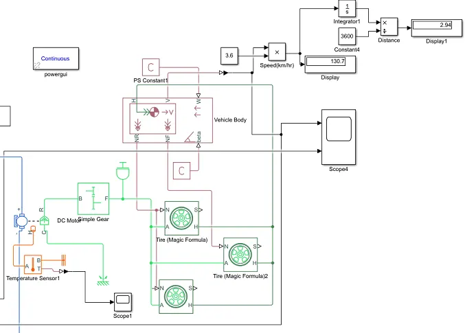
The Drivetrain system consists of blocks like DC motor, simple gear, ineartia, tyres, vehicle body, temperatur sensor, scope. Here the output form H-bride is connected to inout of DC motor and its output is connected to simple gear system which then transmitted to tyres of vehicle and in the vehicle body block all the vehicle inoutds are given. The PS constant is connected to vehicle body, the output from vehicle body is m/s to it is converted to km/hr and from the distance travelled is found in km. Then output cycle and input drive cycle is compared in scope and the temperature of DC motor is plotted.
DC Motor:
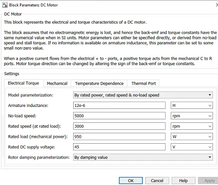
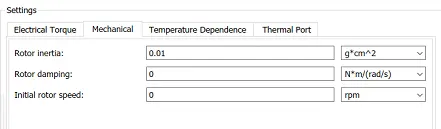
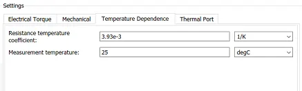
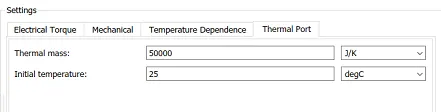
Here the model parameters is set to rated power and rated speed and other input values are also given. Here we have to measure temperature of motor so we have to open thermal port in DC motor block. right click on DC motor block and choose simscape option and in that choose block choices and there select show thermal port
Simple Gear:
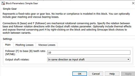
The gear ratio is set to 10 and the output shaft rotates in same way as input shaft


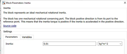
Inertia:
The inertia value is set to 0.01
Tyre:
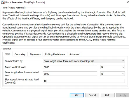
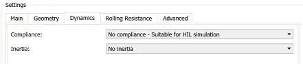
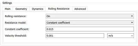
In this block all the input parameters for tyre is given and they are in below images.


Vehicle body:
In this block the mass of vehicle is given as 682kg and other parameters like frontal area, drag coefficient, air density, CG height are given
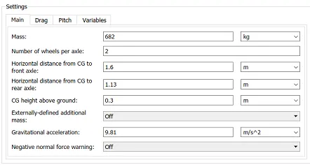
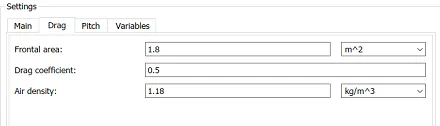

Output:
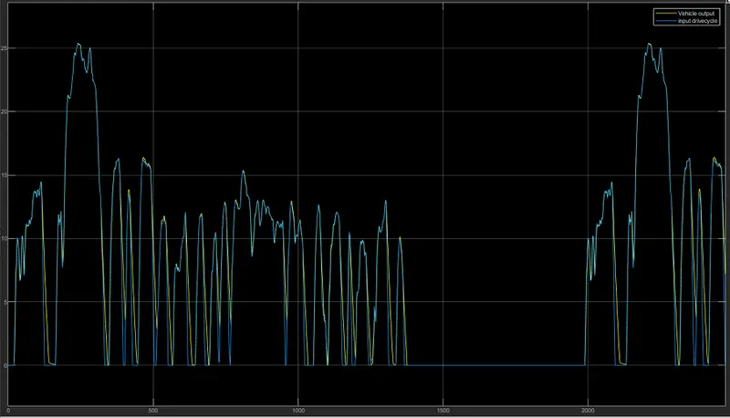
FTP:
Here we can see both input drive cycle and output cycle is comapred and both looks similar.
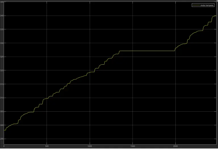
The motor temperature gradually rises from 298K (25 degree celsius) to 340K ( 66 degree celsius)
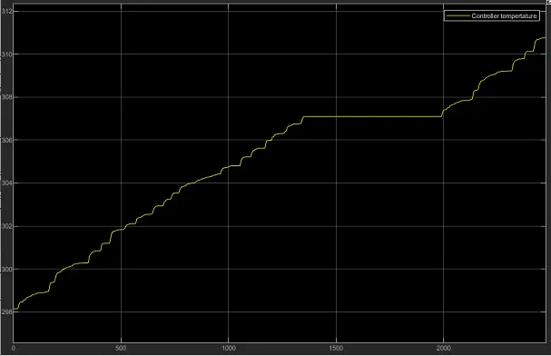
The controller temperature also gradually rises from 298K ( 25 degree celcius) to 311k ( 37.85 degree celsius)
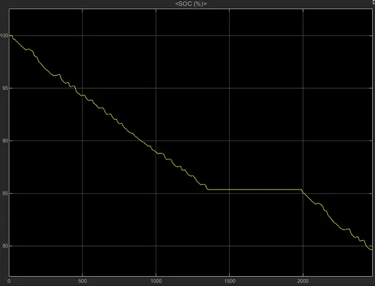
State of charge of vehicle for this drive cycle is reduced from 100% - 80%
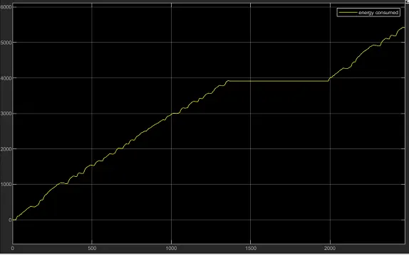
Total energy consumed by vehicle is 5300 wh
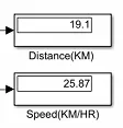
The total distance travelled in this drive cycle is 19km and the speed is 25.87 km/hr
WIDE OPEN THROTTLE:
Here we can see both input drive cycle and output cycle is comapred and both looks similar.
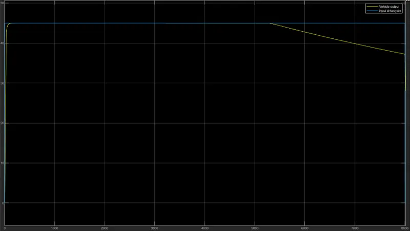
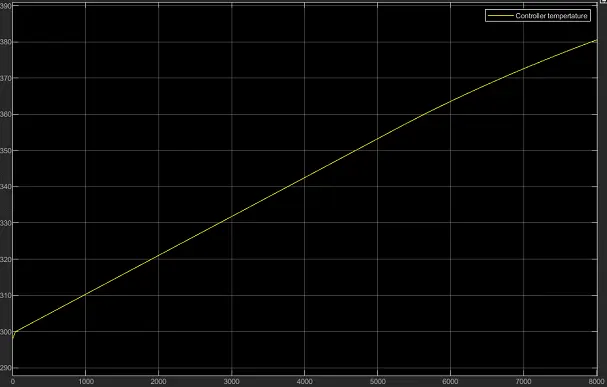
The controller temperature also gradually rises from 298K ( 25 degree celcius) to 381k ( 107.85 degree celsius)
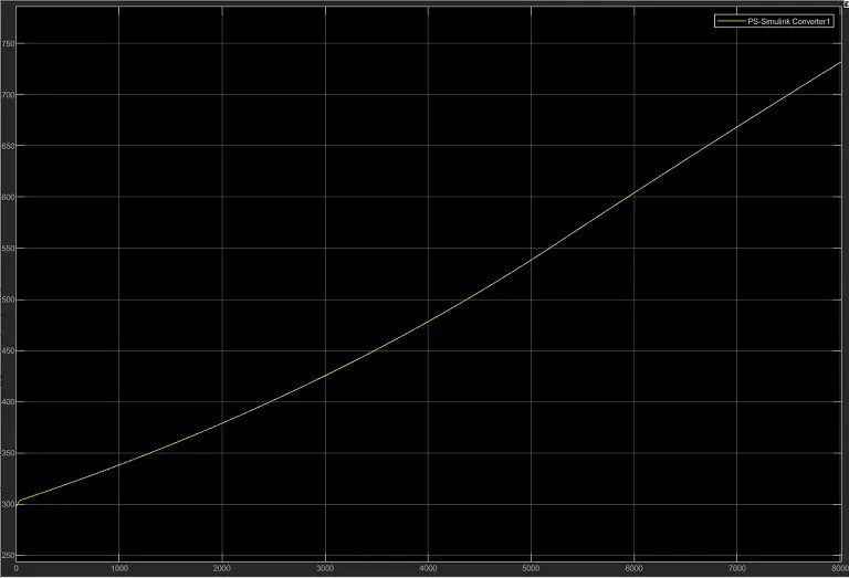
The motor temperature gradually rises from 300K (26.85 degree celsius) to 725K ( 451.85 degree celsius)
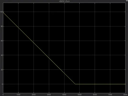
The SOC of vehicle reduces rapidly and reaches 0% at 4800 seconds
Total energy consumed by vehicle for this drive cycle is 25000wh
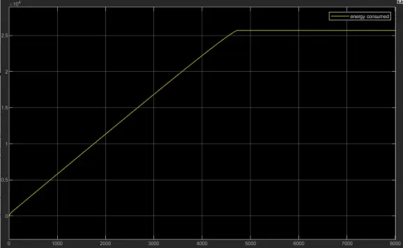
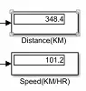
The total distance travelled in this drive cycle is 348.4km
Custom Drive cycle:
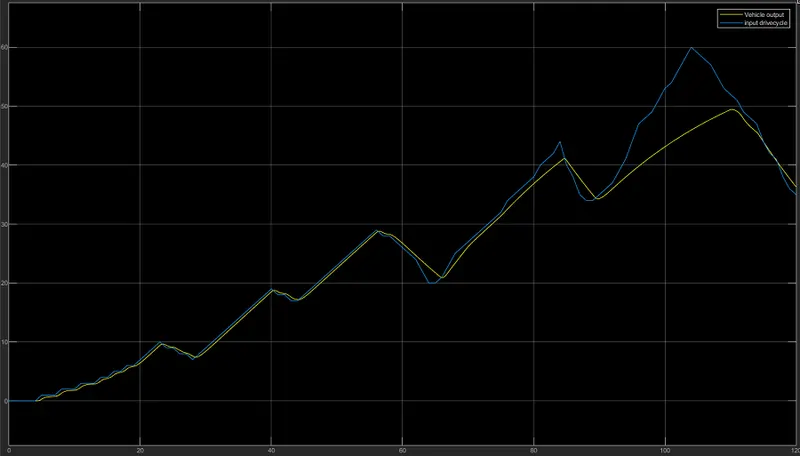
Here we can see both input drive cycle and output cycle is comapred and both looks similar.
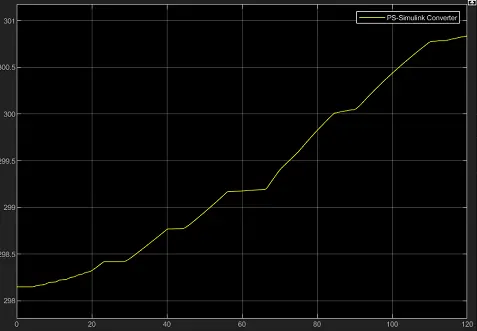
The motor temperature gradually rises from 298.2K (25.05 degree celsius) to 300.75K ( 27.6 degree celsius)
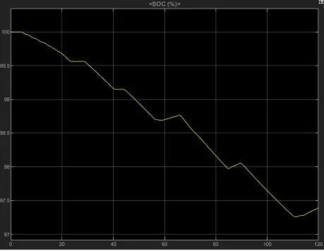
The state of charge of vehicle for this drive cycle is reduced from 100% - 97.25%
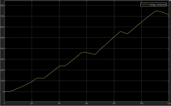
Total energy consumed by vehicle for this drive cycle is 720wh
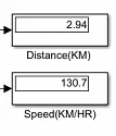
The distance travelled by vehicle is 2.94 km and at speed of 130.7 km/hr.
Input parameter are noted in excel sheet and it is attached