Final Project: Electric Rickshaw modelling
OBJECTIVE:
Create a detailed MATLAB model of an electric rickshaw (three-wheel passenger vehicle) as per details below:
Rear wheels driven by PM brushed type motor
Assume efficiency points of motor controller and motor
Make an excel sheet of all input and assumed data
Results: For any three standard driving cycles show energy consumption, temperature rise of motor and controller for 100 km constant speed driving at 45 kmph.
AIM:
To build a detailed MATLAB model of an electric rickshaw (three-wheel passenger vehicle).
OBJECTIVE:
- The rear wheels are driven by PM brushed-type motor
- Assume the efficiency points of the motor controller and motor
- Make an excel sheet of all input and assumed data
Block Diagram of Electric Rickshaw Drivetrain:
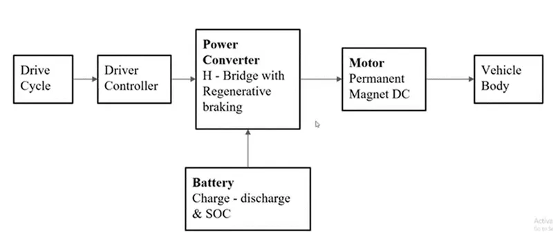
From the above block diagram, we can observe the electric vehicle blocks arrangement. Then the drive train of the Electric rickshaw is shown below:
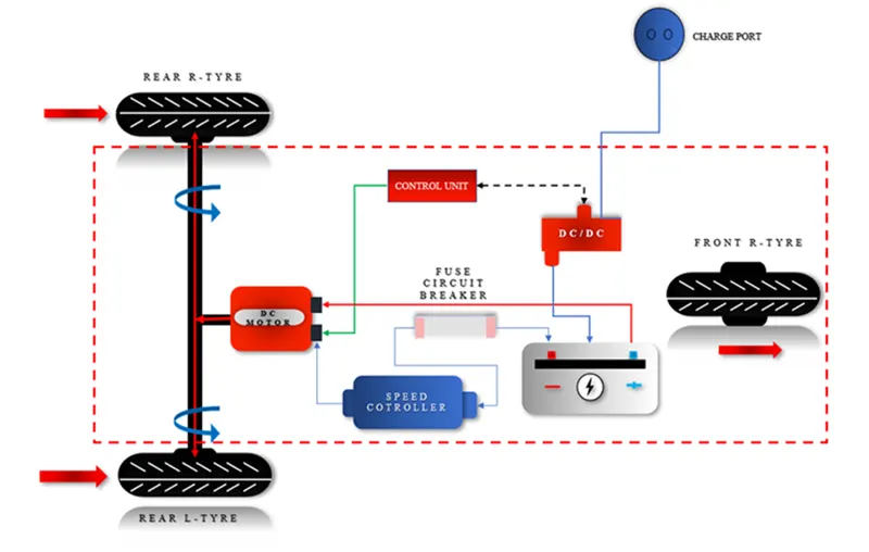
The drive train of the electric rickshaw is having the below equipment:
DC motor
Battery
Controller
Power converter
Transmission
Drive cycle source
PM brushed-type motor:
The brushed motor is one of the earliest and simplest motors as it implements the laws described above in the simplest manner. In this blog, we'll learn about the Brushed DC motor working principle and applications.
What is a Brushed DC motor?
Brushed DC motors are one of the simplest types of DC motors. It uses brushes to deliver current to the motor windings through mechanical commutation.
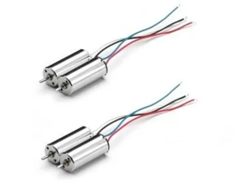
The number of coils wound around the motor and the density of the coils determine the properties of the motor. The armature or rotor is an electromagnet. The field magnet is a permanent magnet. This motor does not require any controller to operate or vary the speed.
Construction of Brushed DC motor:
It typically consists of a pair of permanent magnets named the stator and a motor coil named the rotor connected to a commutator. In this motor, armature winding is on the rotor and permanent magnets are always on the stator.
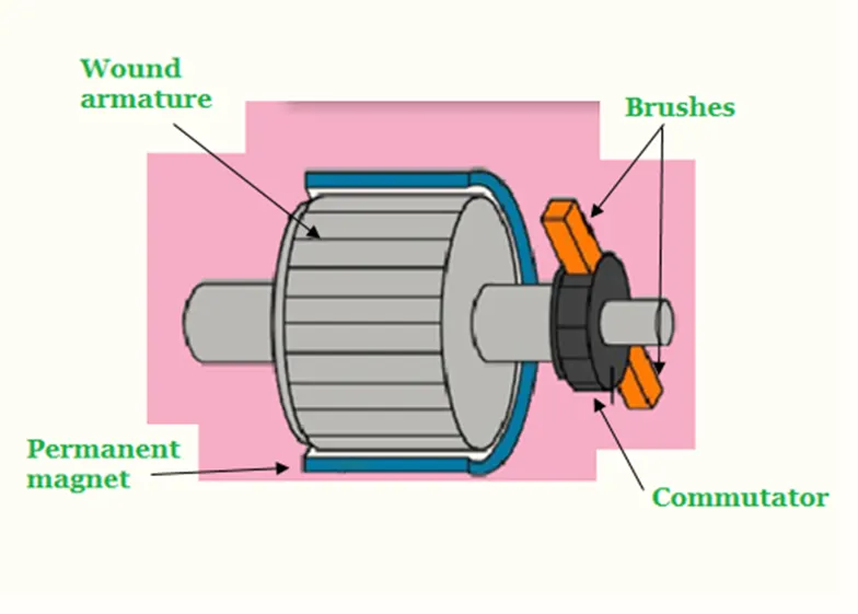
The current-carrying conductors always locate the turning part. practically, these conductors get power from direct current power sources. It uses metallic brushes (which rotate along with the rotor) to transfer the current to the coil. Though these motors are quite efficient they require periodic maintenance of brushes.
Brushed DC Motor Working Principle:
When power supplies to the motor through a battery or any DC source, electricity flows from the source to the armature through the brushes which usually locates on opposite sides of the motor shaft. Brushes are a very important part of this motor. These brushes transfer electric current to the armature through physical contact with the commutator.
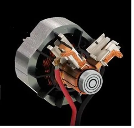
As soon as the armature coil gets energy or power, it begins to behave like a magnet. And at this point, its poles start repelling the poles of the permanent magnet which makes up the stator. As the poles repel, the motor shaft where the armature coils are attached begins to rotate with speed and torque. The Speed and torque depend on the strength of the magnetic field around the armature.
Usually, the strength of the magnetic field is a function of the voltage applied to the brushes and the strength of the permanent magnet used for the stator.
Battery:
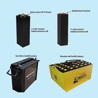
The traction battery pack is also known as an Electric vehicle battery (EVB). It powers the electric motors of an electric vehicle. The battery acts as an electrical storage system. It stores energy in the form of DC current. The range will be higher with increasing kW of the battery. The life and operation of the battery depend on its design. The lifetime of a traction battery pack is estimated to be 200,000 miles.
Controller:
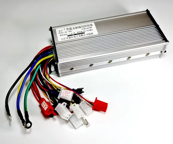
Controllers The electric vehicle controller is the electronics package that operates between the batteries and the motor to control the electric vehicle‘s speed and acceleration much like a carburetor does in a gasoline-powered vehicle. The controller transforms the battery’s direct current into alternating current (for AC motors only) and regulates the energy flow from the battery. Unlike the carburetor, the controller will also reverse the motor rotation (so the vehicle can go in reverse), and convert the motor to a generator (so that the kinetic energy of motion can be used to recharge the battery when the brake is applied). In the early electric vehicles with DC motors, a simple variable-resistor-type controller controlled the acceleration and speed of the vehicle. With this type of controller, full current and power were drawn from the battery all of the time. At slow speeds, when full power was not needed, high resistance was used to reduce the current to the motor. With this type of system, a large percentage of the energy from the battery was wasted as an energy loss in the resistor. The only time that all of the available power was used was at high speeds. Modern controllers adjust speed and acceleration by an electronic process called pulse width modulation. Switching devices such as silicone-controlled rectifiers rapidly interrupt (turn on and turn off) the electricity flow to the motor. High power (high speed and/or acceleration) is achieved when the intervals (when the current is turned off) are short. Low power (low speed and/or acceleration) occurs when the intervals are longer. The controllers on most vehicles also have a system for regenerative braking. Regenerative braking is a process by which the motor is used as a generator to recharge the batteries when the vehicle is slowing down. During regenerative braking, some of the kinetic energy normally absorbed by the brakes and turned into heat is converted to electricity by the motor/controller and is used to recharge the batteries. Regenerative braking not only increases the range of an electric vehicle by 5 - 10%, it also decreases brake wear and reduces maintenance costs
Power converter:
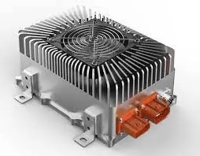
The different configurations of EV power supply show that at least one DC/DC converter is necessary to interface the FC, the Battery, or the Supercapacitors module to the DC-link.
In electrical engineering, a DC-to-DC converter is a category of power converters and it is an electric circuit that converts a source of direct current (DC) from one voltage level to another, by storing the input energy temporarily and then releasing that energy to the output at a different voltage. The storage may be in either magnetic field storage components (inductors, transformers) or electric field storage components (capacitors).
DC/DC converters can be designed to transfer power in only one direction, from the input to the output. However, almost all DC/DC converter topologies can be made bi-directional. A bi-directional converter can move power in either direction, which is useful in applications requiring regenerative braking.
The amount of power flow between the input and the output can be controlled by adjusting the duty cycle (ratio of the on/off time of the switch). Usually, this is done to control the output voltage, the input current, and the output current, or to maintain constant power. Transformer-based converters may provide isolation between the input and the output.
Transmission:
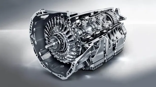
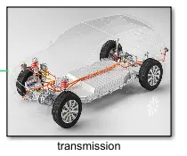
It is used to transfer the mechanical power from the electric motor to the wheels, through a gearbox. The advantage of electric cars is that they do not require multi-speed transmissions. The transmission efficiency should be high to avoid power loss.
Drive cycle source:
The Drive Cycle Source block generates a standard or user-specified longitudinal drive cycle. The block output is the specified vehicle longitudinal speed, which you can use to:
- Predict the engine torque and fuel consumption that a vehicle requires to achieve desired speed and acceleration for a given gear shift reference.
- Produce realistic velocity and shift references for closed-loop acceleration and braking commands for vehicle control and plant models.
- Study, tune, and optimize vehicle control, system performance, and system robustness over multiple drive cycles.
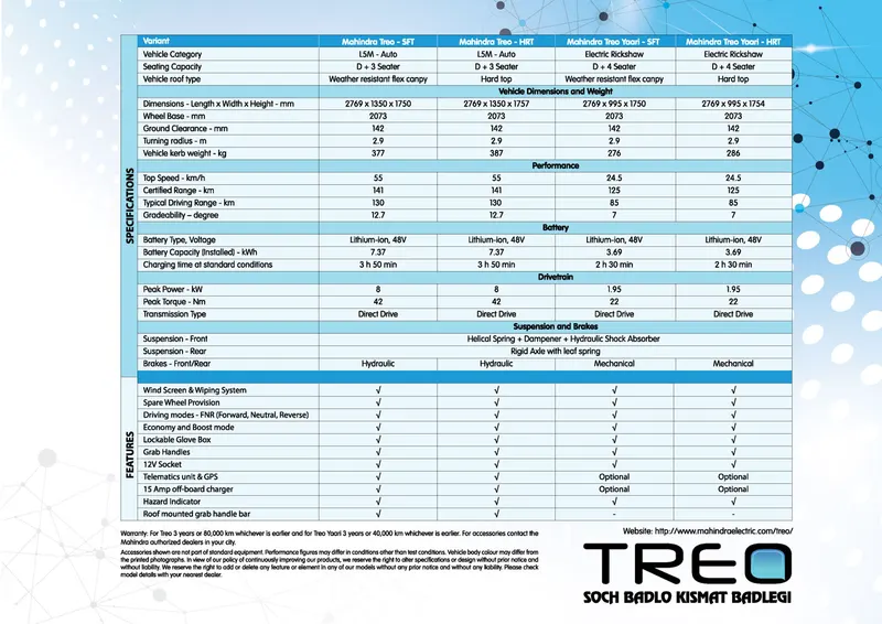
Mahindra Treo Data Sheet:
Mahindra Treo is taken as a reference for this project.
The simulation Model is shown below:
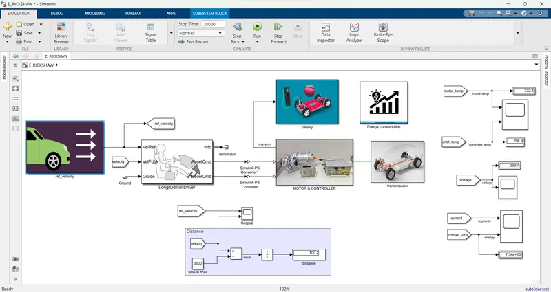
Blocks used in this simulation are listed below:
Drive cycle source
Signal builder
Constant
Slider gain
Multiport switch
Longitudinal driver
Terminator
Simulink-PS converter
PS-Simulink converter
Powergui
Connecting port
Controller voltage source
Controlled PWM voltage
H-bridge
Solver configuration
Electrical Reference
Current Sensor
Temperature Sensor
Thermal Reference
Goto
From
Current sensor
Outport
Inport
DC Motor
Mechanical rotational reference
Voltage Sensor
Model Explanation:
In this project, we build Electric Rickshaw Simulink model. For this model, we use Simulink primitive blocks.
For the Ref_velocity Subsystem:
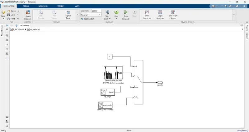
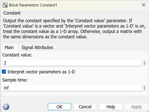
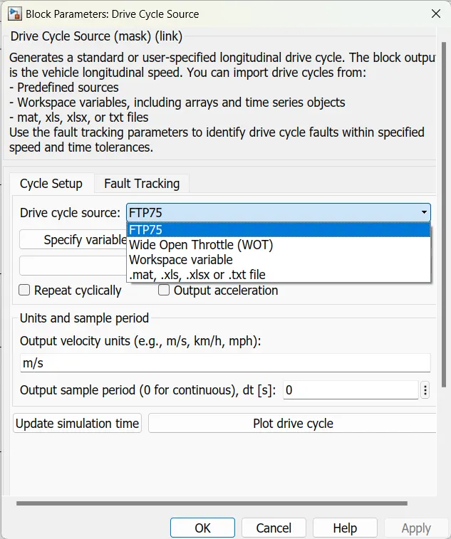
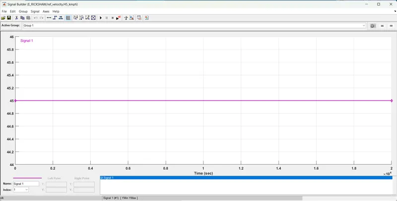
The properties of each block in the ref_velocity subsystem are shown below:
UDDS Drive cycle excel data:
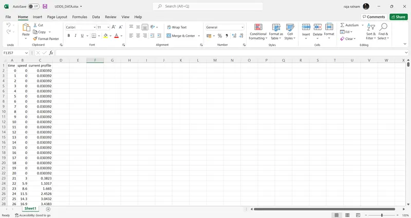
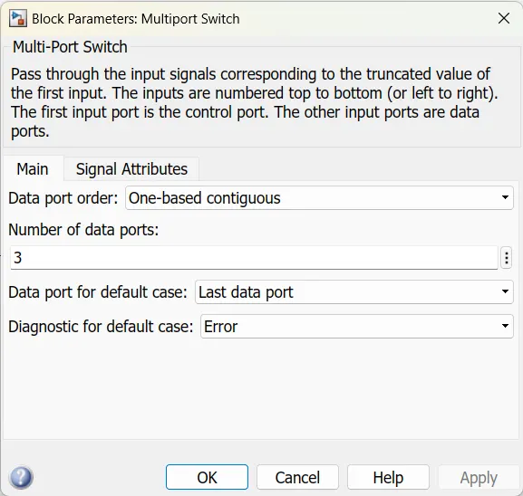
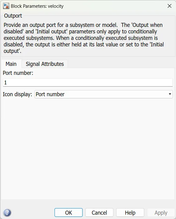
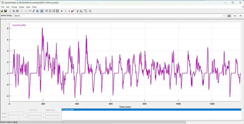
In this subsystem, we are taking a Drive cycle Source (FTP75 with 2474 seconds), a signal builder with 45 kmph for 20000 seconds, and a UDDS drive cycle with 1369 seconds given to a multiport switch. This multiport switch has three input data terminals and one control port. For the control port, a constant block is taken as input and in this constant block, we give the drive cycle port number as we are required to run for the simulation according to our test requirement. The multiport switch output is given to an outport named velocity.
Longitudinal Driver:
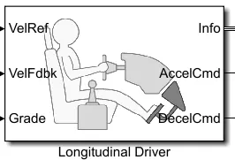



This longitudinal driver block has three input ports (Velref, VelFdbk, and Grade) and three output ports (info, Accelcmd, and decelcmd). For the velref port, input is taken from the ref_velocity subsystem. For VelFdbk port input is taken from the Transmission subsystem as a feedback signal from the vehicle body. The grade port is connected to the ground. Accelcamd and Decelcmd ports are connected to the motor& controller subsystem block accelcmd and decelcmd ports with Simulink to PS converter. The info port is connected to the terminator block.
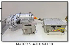
Motor & Controller subsystem:
Blocks properties:
H-BRIDGE:
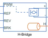
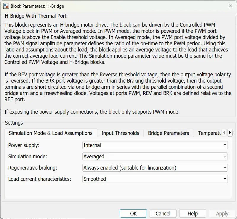
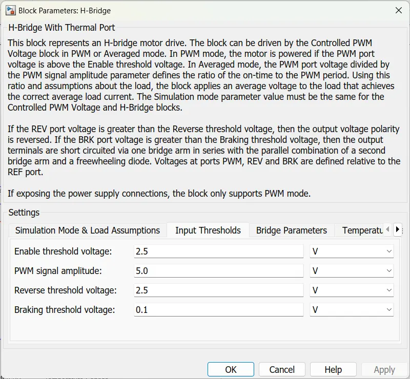
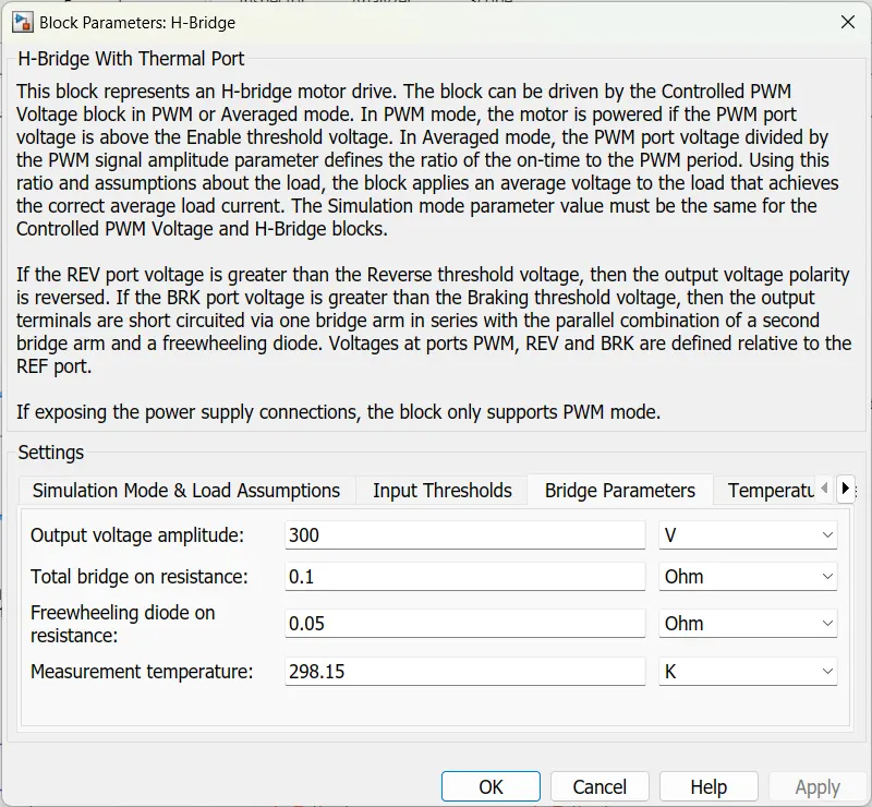
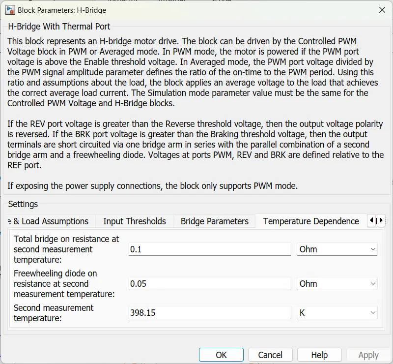
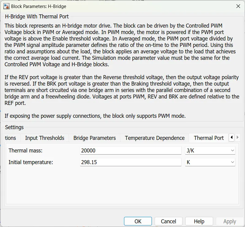
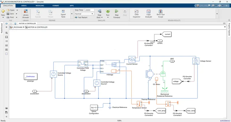
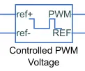
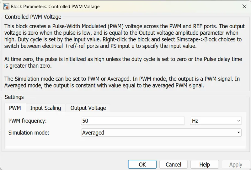
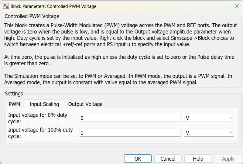
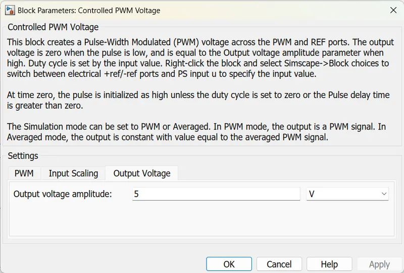
This subsystem has two input ports and two outports. A controlled voltage source block is taken and it is connected to the controlled PWM voltage block positive ref port. Then the negative ref port is connected to common. The controlled voltage source block input is connected to a connecting port named acceleration. This is connected to the acccmd port. The PWM port Is connected to the h-bridge PWM inport and the ref ports are connected to each other. The Brk input port was connected to a controlled voltage source block and it is connected to a connecting port named deceleration. This h-bridge has a thermal port and it is connected to a temperature sensor port A. and another B port is connected to the thermal reference block. the T port is connected to the goto tag via a PS-Simulink converter.
DC Motor:
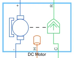
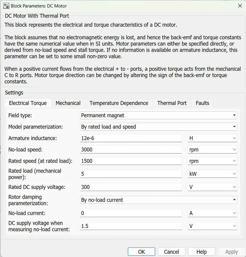
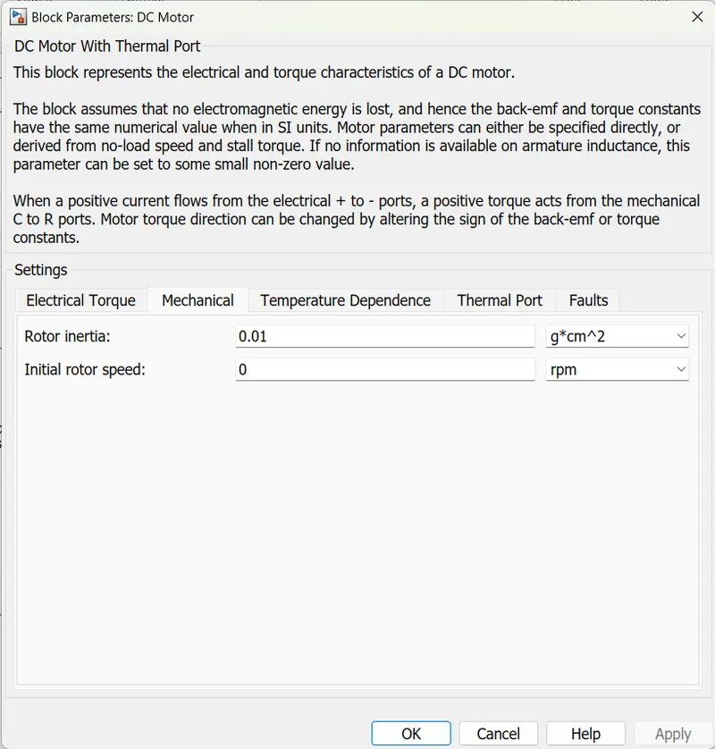
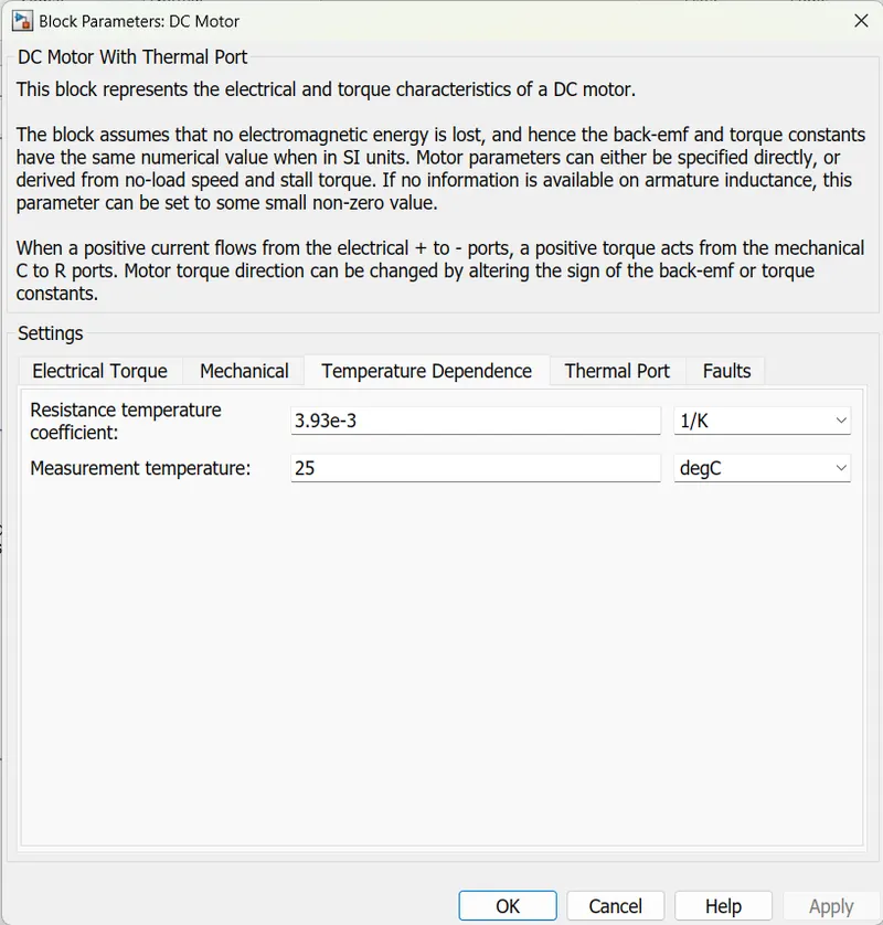
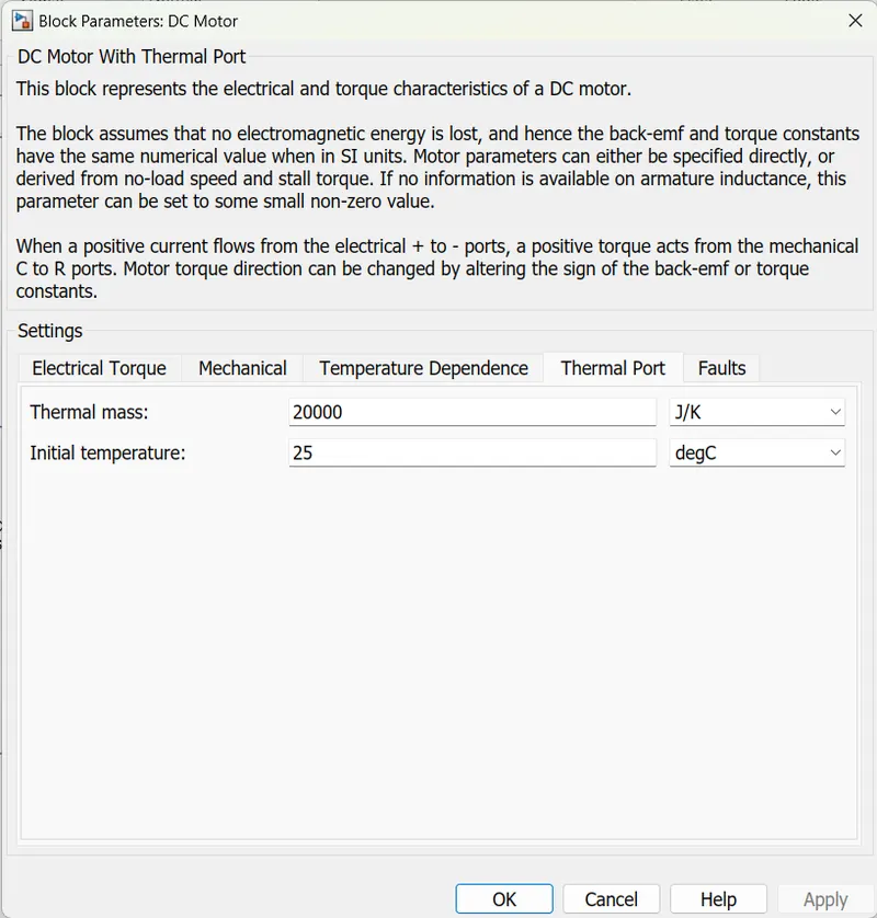
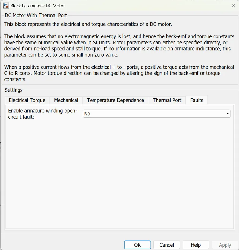
A current sensor is connected between H-bridge and DC motor to measure the current and the current sensor block source port is connected to an outport via the PS-Simulink converter. The Dc motor positive terminal is connected to the current sensor negative port and the motor negative port is connected to the electrical reference and the motor mechanical port R is connected to connecting port named gear and the C port is connected to the mechanical rotational reference. From the DC motor thermal port, the thermal signal is given to a temperature sensor. And the temperature sensor port B is connected to the thermal reference. The outport T is connected to a goto tag via the PS-Simulink converter. A voltage sensor is connected in parallel with the dc motor to measure the voltage and the sensor block source port is connected to the goto tag named voltage via the PS-Simulink converter block. from this subsystem current and gear are the outputs. A solver is connected to the common connection terminal and an electrical reference is connected. A Powergui block is taken for the continuous operations of the model.
Transmission:
Vehicle body:
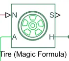
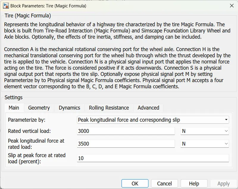
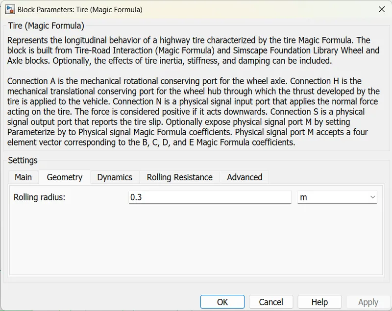
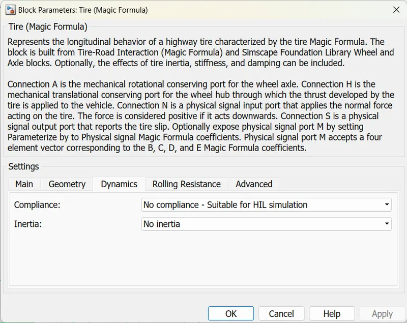
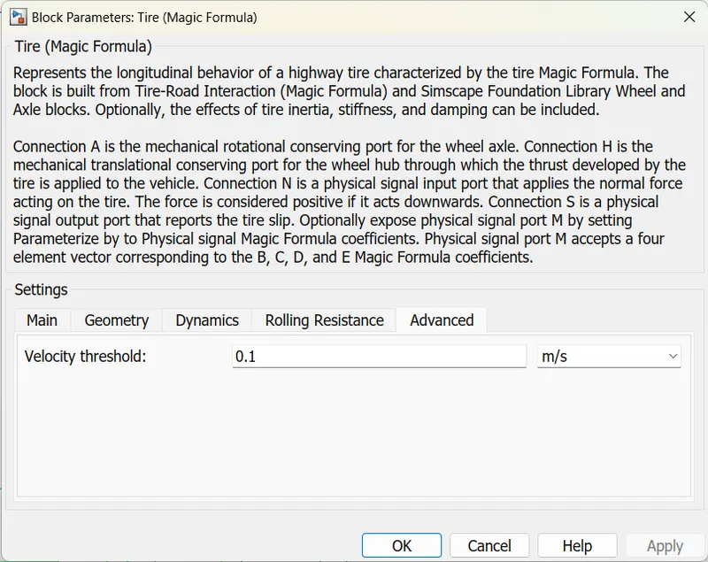
Tire:
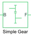
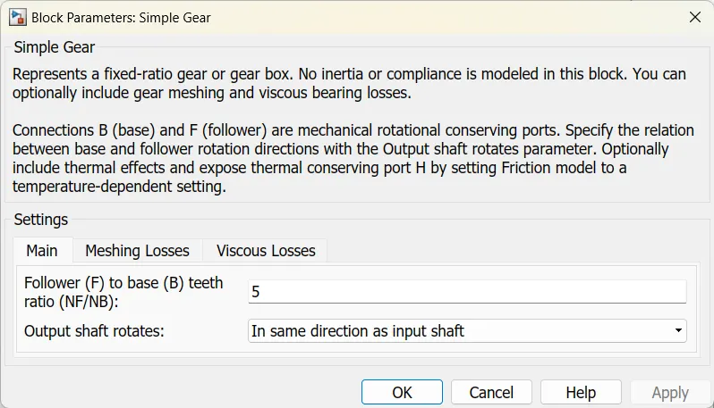
Gear:
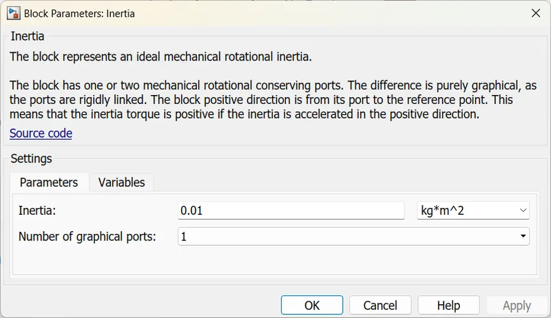
Inertia:

Ps-Constant:
Rotational free end:
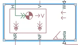
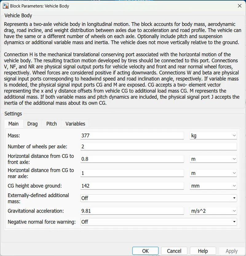
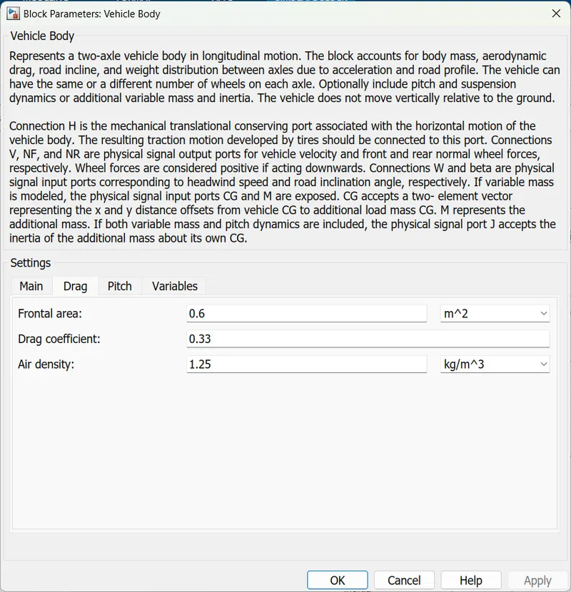
The transmission subsystem input is taken from the controller block. a connecting block named gear is the input of the subsystem block and it is connected to the simple gear block inport. Then its output is connected to the Inertia block. according to the given requirement, the rear wheels are driven by a pm brushed motor. Two wheels are taken as rear wheels and the wheels have four ports. Wheels axels are connected together and the inertia block is connected to the axels and the N port is connected to the vehicle body NR port. And the H port is connected to two wheels and the vehicle body H port is connected to the wheels’ H port. The vehicle body block is having Velocity port V and it is connected to the goto tag via the PS-Simulink converter for the feedback signal to the longitudinal driver block. the W and beta ports are connected to the ps constant block. The tire (magic formula) for the front wheel is taken and its N port is connected to the NF port of the vehicle body. The H port is connected to the H port of the vehicle body port. The Axel A port is connected to the Rotational Free end block.
Battery:
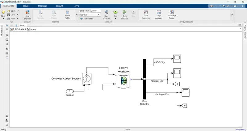
Battery:
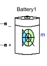
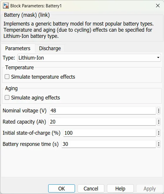
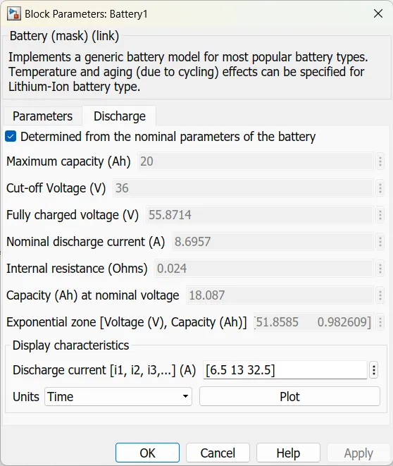
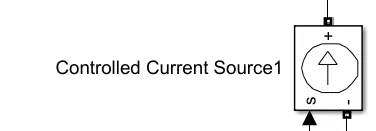

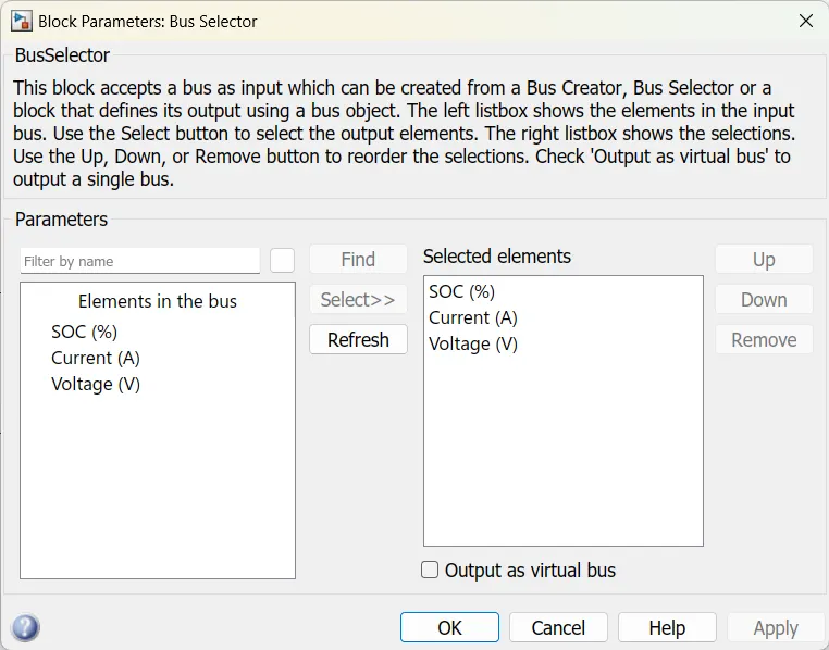
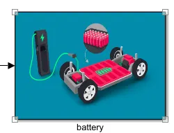
In this battery, subsystem the input from the controller subsystem is taken and given to the controller’s current source block source port. The controlled current source block positive port is connected to the battery negative port. And the current source negative port is given to the positive port. From the battery measurement port output signal is given to the bus selector block here the signals are selected and given to the scope to observe the output. Soc, voltage and current signals are taken for the scope. The voltage and current signals are connected to Goto blocks for energy consumption calculations.
Energy Consumption:
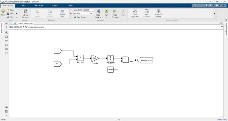
For energy consumption, the voltage and current are taken from the battery. Voltage and current signals are multiplied with the product block and given to a gain block to convert the watts to kilowatts then it is integrated with an integrator and the output is divided with the 3600 with the divided block the output is in kwh and it was given to the goto block.
Distance:
For the distance calculation, we are taking the velocity from the transmission subsystem and dividing it by 3600 the velocity is converted into kmph and then integrated with an integrator the distance in km can be observed in the display block.
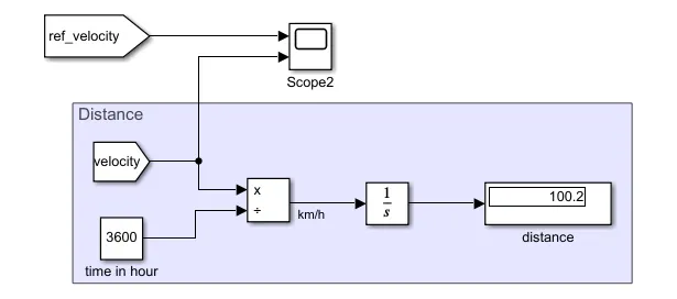
Motor, controller temperature, voltage, current, energy consumption, and soc response are observed in the scopes and displays connected to the relevant “from” tags.
Result:
Test-1: FTP75 Drive cycle.
The FTP75 drive cycle is taken as a source for the simulation with the 2474 seconds running time.
The motor and controller temperature in K:
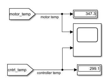
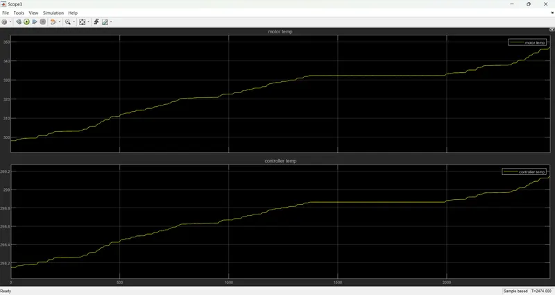
The motor temperature is raised to 347.3 and the Controller temperature is Raised to 299.1C
The plot for the motor and controller temperature is shown below.
Ref_velocity and vehicle velocity are shown below:
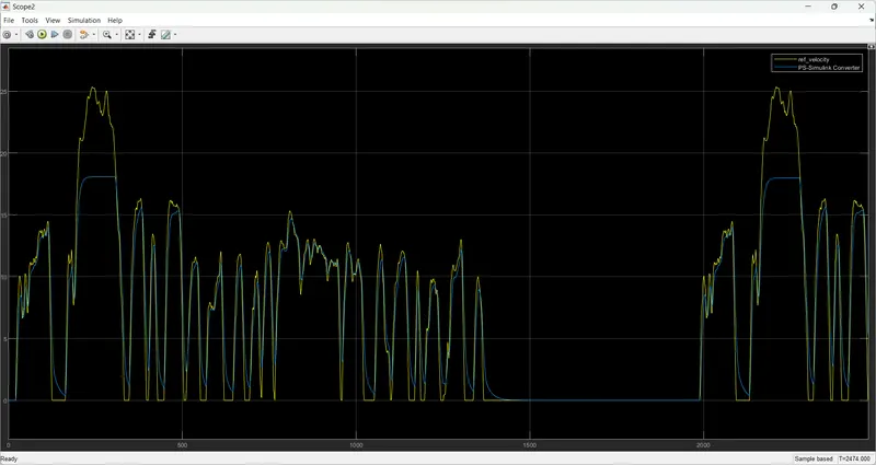
in the above plot, we can observe the reference velocity in the yellow line and the actual velocity in the blue line.
the actual velocity is tracking the reference velocity with small variations.
Energy consumption in kWh:
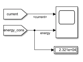
the energy consumed is 2.321e+04 kwh
here we can see the plots, of motor current and energy consumption response.
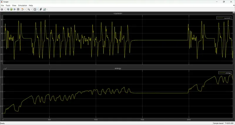
the motor current varies according to the drive cycle. when the brake is applied the motor is in regenerative mode.
here we can observe the wave when the regenerative mode on the wave is in the negative region.
the energy consumed is observed in the above plot.
Motor voltage:
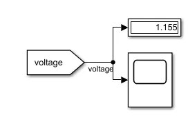
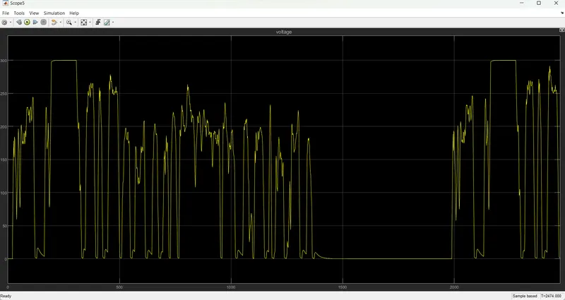
the voltage measurement across the dc motor is shown in the above figure. the voltage is 1.155 volts.
plot:
Distance:
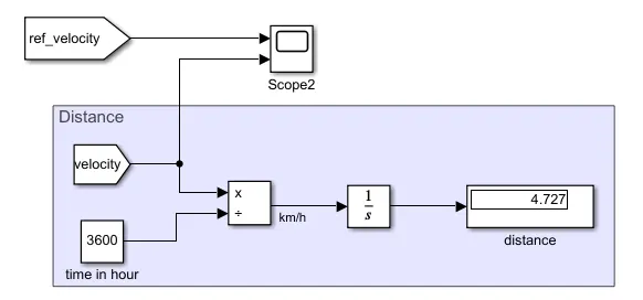
the vehicle with FTP75 drive cycle input traveled a 4.7km distance.
Test-2: 45 kmph.
For this test drive cycle input is taken in the signal builder:
Signal Builder:
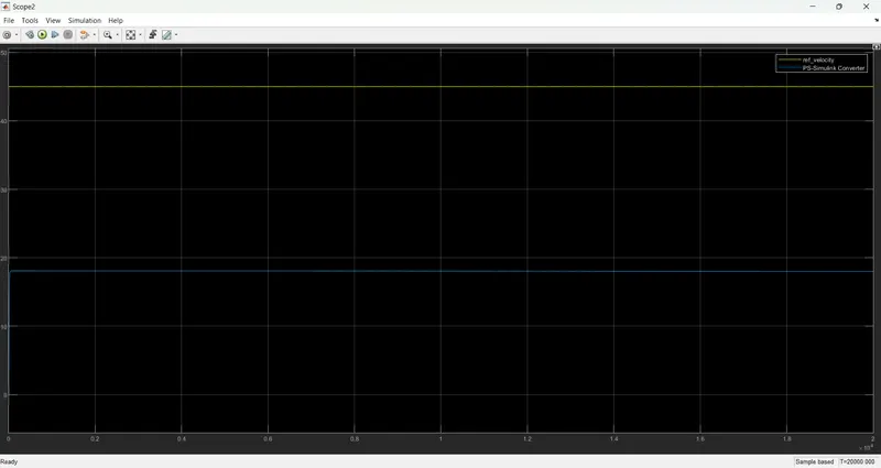
in this test, we are taking 45kmph as input signal for 20000 seconds running time to achieve the 100 km distance.
Motor and controller temperatures in K:
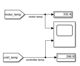
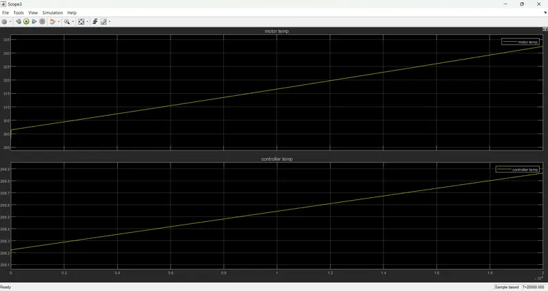
motor temperature is 332.4c. and the controller temperature is 298.9c
the plot is shown below:
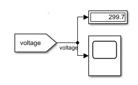
voltage:
plot:
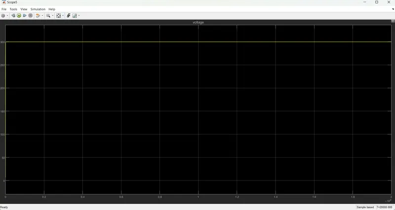
The voltage across the motor is 299.7v
Velocity:
Current and Energy consumption:
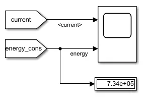
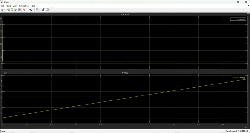
The energy consumed is 7.34e+05
SOC:
Distance:
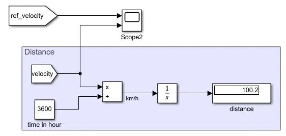
When the simulation runs for 20000 seconds with the 45kmph the distance traveled is 100.2km.
Test-3: UDDS
UDDS Drive cycle is used as input and runs for 1369 seconds.
Signal builder with custom Drive cycle:
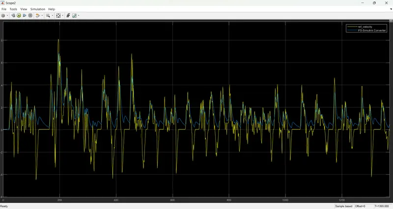
Velocity:
Motor and controller temperatures in K:
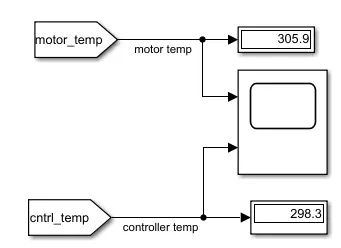
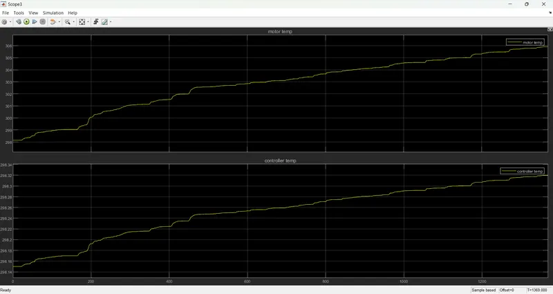
the motor and controller temperatures are 305.9k and 298.3k. then the response is observed graphically in the below plots.
Voltage:
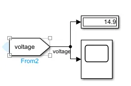
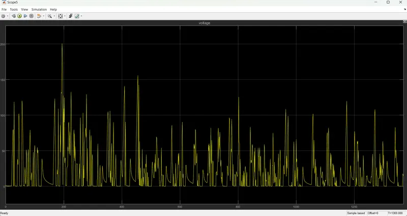
the voltage across the dc motor is 14.9v.
Current and energy consumption:
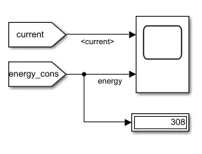
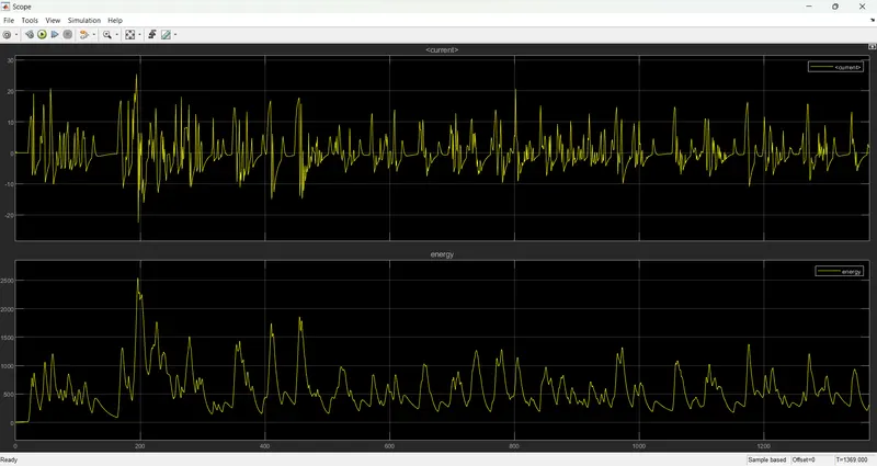
the energy consumption is 308 we can observe the response in the below plot.
Distance:
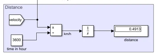
to calculate the distance we divide the velocity by 3600 and integrate the output. the distance is 0.49km