Final Project: Electric Rickshaw modelling
AIM ---electric rickshaw design (three-wheel passenger vehicle)
In this project, we going to build the MATLAB model of the ELECTRIC RICKHAEW by using a PM brushed type DC motor and a suitable Lithium-Ion battery for the motor. Before that, we will know about what is Electric RICKHAEW, how it works, and its benefits of EV RICKHAE. Then we make an actual EV RICKHAEW model in SIMULINK with suitable blocks from the powertrain block set.
The rear wheels are driven by PM brushed-type motor
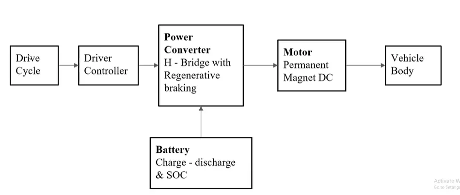
In the designed Electric Rickshaw main blocks are Battery, drive cycle, controller, DC Motor, Vehicle body & Transmission system. Drive cycle is the input data like how a human drive his actual vehicle here FTP75, WOT
drive cycles are used to make the designed vehicle to give the output how it reacts to the drive cycle. The main objective is to obtain the speed by the driver, to estimate the temperature of the Motor and Controller, estimate the states of charge (SOC), and the distance traveled by the vehicle. There is a SOC block that will estimate the state of charge of a battery, distance is calculated by speed and time parameters for all three Drive cycles.
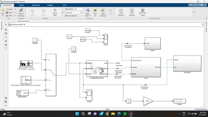
model of the E-rickshaw
(1) Vehicle Body Subsystem Model :
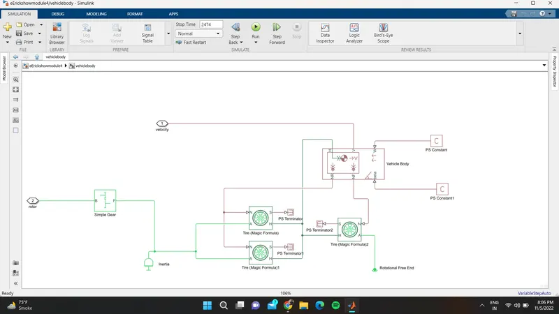
simple gear---------
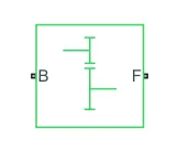
- Connections B (base) and F (follower) are mechanical rotational conserving ports. Specify the relation between base and follower rotation directions with the Output shaft rotates parameter.
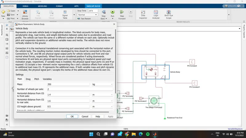
vehicle body----------
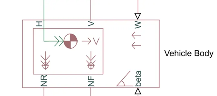
- Connections V, NF, and NR are physical signal output ports for vehicle velocity and front and rear normal wheel forces, respectively. Wheel forces are considered positive if acting downwards.
- Connections W and beta are physical signal input ports corresponding to headwind speed and road inclination angle, respectively.
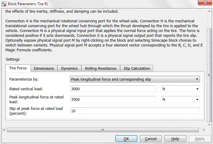
Tire:
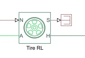
Connection A is the mechanical rotational conserving port for the wheel axle
Connection N is a physical signal input port that applies the normal force acting on the tire
Connection S is a physical signal output port that reports the tire slip.
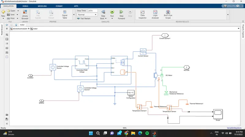
Motor & Power Converter Subsystem Model (With Temperature Sensor) :
H-Bridge :
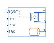
As the name indicates that the H symbol in the block is connected to the DC motor and the PWM, REF, REV, and BRK are used to control the block DC motor.
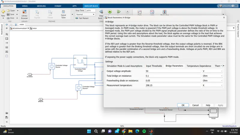
The block can be driven by the Controlled PWM Voltage block in PWM or Averaged mode. In PWM mode, the motor is powered if the PWM port voltage is above the Enable threshold voltage
DC Motor :
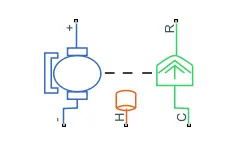
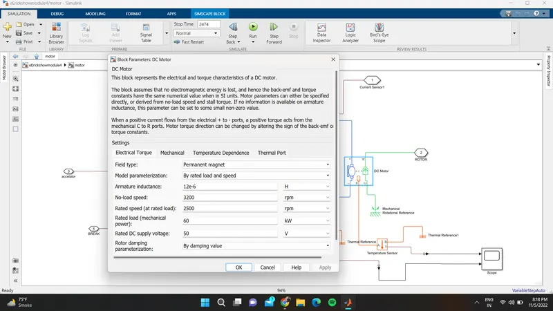
It is used to convert electrical energy to mechanical energy. In this electric vehicle model, we have used a type is permanent magnet DC motor. This motor can also act as a generator in the case of regenerative braking.
In this block, the motor's electrical side is represented with the blue color and the mechanical side is represented with green as well with the combination of shaft which is in the dotted line. here the motors +ve and -ve terminals are connected to the H-Bridge +ve and -ve terminals respectively with the electrical reference in the -ve side.
Controlled PWM Voltage :
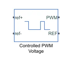
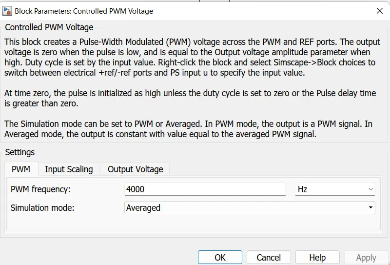
It is used to give the Pulse Width Modulation signals to the H bridge circuit at the PWM terminal. The +ve reference terminal of the block is connecter to the controlled voltage source and -ve is connected to the electrical reference, the PWM is connected to the H bridge PWM as said above and REF is connected to the REF and REV terminals of the H bridge.
Electrical reference:
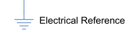
It is used to connect all the terminals of the negative signals and the reference values as the ground.
Ps-Simulink converter:
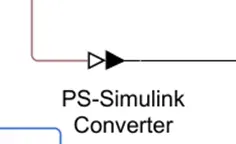
It is used to connect the line from the physical signal to Simulink which act as a converter.
Mechanical rotational reference:
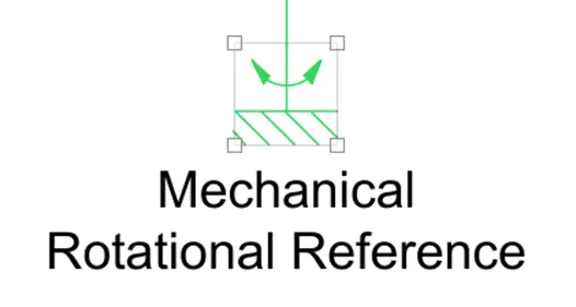
It is represented as a mechanical ground reference point that is as a frame part that is used to connect rotational parts to the ground
Temperature Sensor :
- A temperature Sensor is used to measure the temperature of the H-Bridge and Motor.
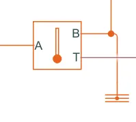
- This block measures temperature in a thermal network. There is no heat flow through the sensor. The physical signal port T reports the temperature difference across the sensor.
- The measurement is positive when the temperature at port A is greater than the temperature at port B.
- Battery And Soc Subsystem Model :
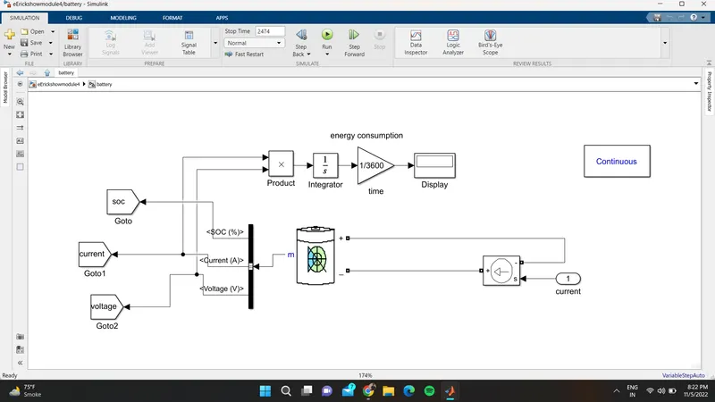
Battery :
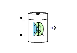
We can say that the battery is one of the main important parts or the block in the vehicle and model as well. By connecting this terminal to the controlled voltage source it supplies controlled signals to discharge and also charging in the regenerative type as well
BUS selector
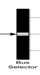
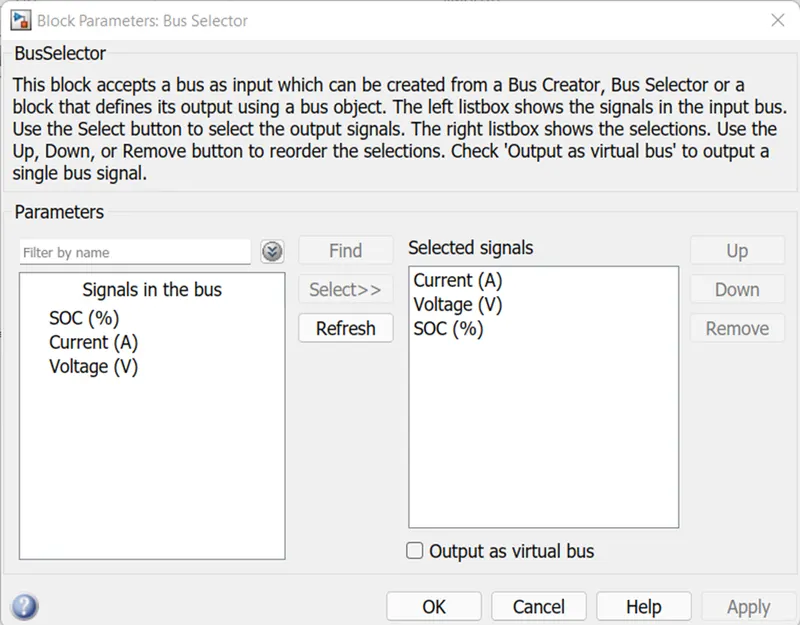
The bus selector is used to block the output signals which are given as an input to that bus selector block
Solver configuration:
It is placed in the power control unit for the mathematical values in the model solver settings at the simulation time
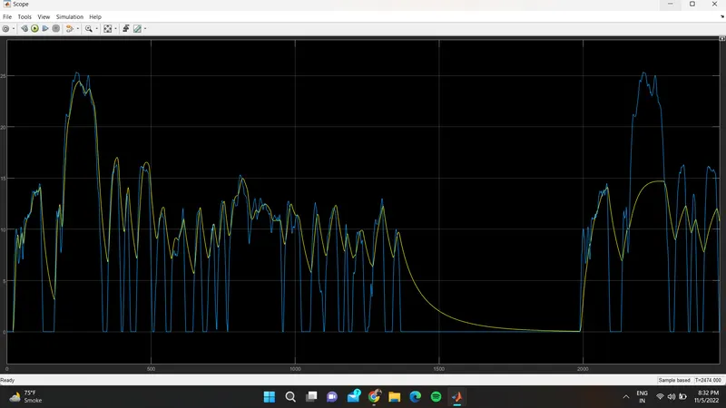
To get the results of this model we have to keep the stop time to 2474 sec or above because of the given drive cycle source with FTP (2474 seconds).
Longitudinal Driver :
- Longitudinal Driver is an inbuilt block provided by the powertrain blocks.
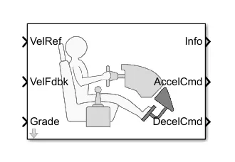
It like a driver which is used to take the charge of driving its acceleration breaking commands as per the given conditions which is called as a reference.
VEL Ref is used to take the reference values for the driver to drive the vehicle.
Vel Fdbk is used to take the feedback from the output of the given data from the vehicle speed which is called as a velocity.
Accel Cmd is an output signal that gives as an input to the power control unit-controlled voltage source 1 which is connected to the PWM for the purpose of acceleration when the output is reduced to lower than the given reference value.
Decel Cmd is also an output signal that gives as an input to the power control unit-controlled voltage source 2 which is connected to the BRK for the purpose of breaking when the output is becoming higher than the given reference value.
Reference Velocity (Drive Cycle) :
in this, we have taken three drive cycle
one is FTP75
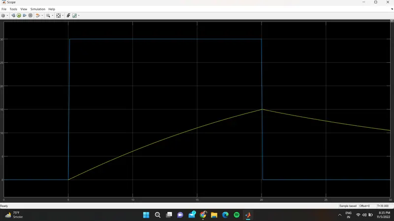
one wot(wide open throttle)
single builder
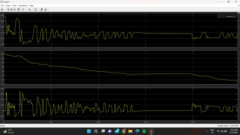
result for FTPF75 drive cycle
result for voltage ,soc,current
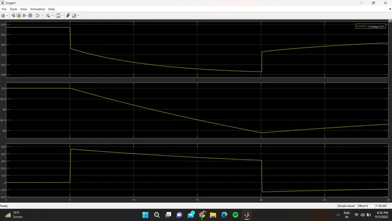
graph for WOT CONDITION
DRIEV CYCLE
SOC,VOLTAGE,CURRENT
Here I have compromised with the temperature of the Motor and controller to achieve vehicle speed is near to reference speeds. Since I haven’t used any cooling system in the model. In the real-time application
THE REFERENCE DRIVE CYCLE CANT NOT PROPERLY OVERLAP THE VEHICLE SEPPED