Final Project: Electric Rickshaw modelling
ELECTRIC RICKSHAW MODELLING
OBJECTIVE:
Create a detailed MATLAB model of an electric rickshaw (three wheel passenger vehicle) as per details below:
Rear wheels driven by PM brushed type motor
Assume efficiency points of motor controller and motor
Make an excel sheet of all input and assumed data
Results: For any three standard driving cycles show energy consumption, temperature rise of motor and controller for 100 km constant speed driving at 45 kmph.
INTRODUCTION:
Electric rickshaws (also known as electric tuk-tuks or e-rickshaws or toto or e-tricycles) are small 3-wheeled vehicles powered by an electric motor and battery ranging from 650 to 1400 Watts. They save on fuel costs compared to auto rickshaws while offering greater ease-of-use than pulled rickshaws. This has led to their popularity and widened-acceptance in some cities since 2008.If introduced in a systematic manner, electric rickshaws could be a low-emitter complementary transport for low-income people who suffer most from a lack of transport facility.They are mostly manufactured in India and China.vElectronic rickshaws have now transitioned from being a market entrant in the automobile industry of India to a leading short-distance transport solution.This segment gained popularity between 2015 and 2018. Although this segment is dominated by a host of unorganized players, established manufacturers have also identified its growth opportunities and are expected to foray into the segment.
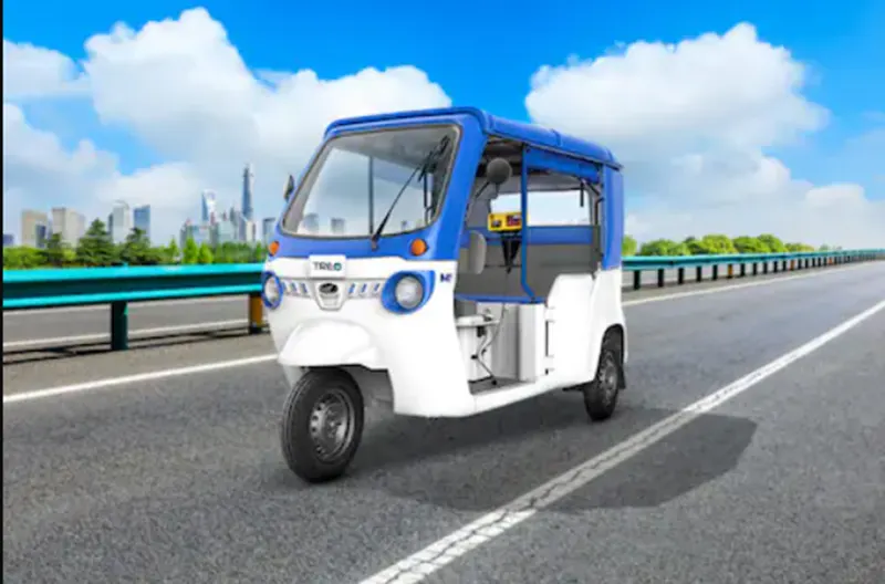
Though e-rickshaws were introduced in India on the lines of China in the late 2010s, sales were very sporadic and not widespread. Due to the drive to have a greener transport industry (especially in tier-2 & tier-3 cities), the e-rickshaw market is vastly gaining base and is likely to gain a foothold in the coming years with the entry of established players in the segment as well.
METHODOLOGY:
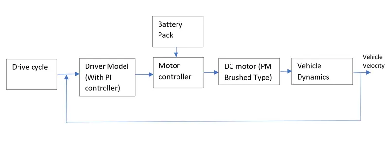
In this project,I am going to create the MATLAB model of an electric rickshaw using the SIMULINK and analyze the results for the different drive cycles using the simulink results by assuming some data.
The E-Rickshaw consist of Battery,Motor,Motor controller,Vehicle body,Wheels etc., we need to design the parameters of the components based on the Range of the vehicle we required and propulsion power required.
Motor is selected based on the power required.
Battery and capacity is selected based on the range of the vehicle.
All the selected components are listed and data is assumed for the components.
The main objective is to find out the Energy Consumption and Temperatur Rise in Motor Controller and Motor for the three different drive cycles and also for the vehicle travelling for 100km at constant speed 45kmph.
BLOCK DIAGRAM:
SOFTWARE USED:
MATLAB R2019a
DESIGN OF ELECTRIC RICKSHAW:
We design the Electric Rickshaw by assuming some data and selected the components based on that.
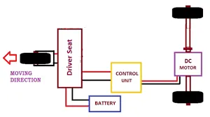
Below image shows the simple architecture of the E-Rickshaw
Vehicle Category - Electric Rickshaw
Seating Capacity - D + 4 Seater
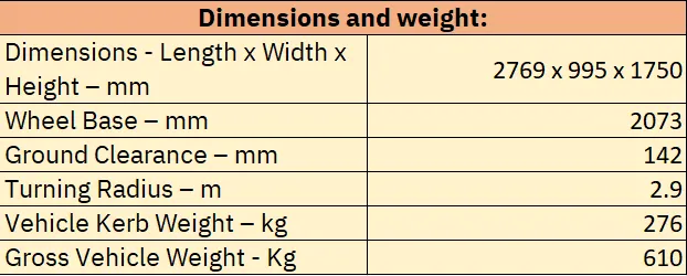
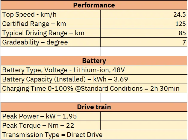
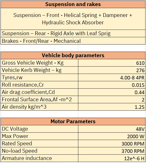
Here the paramaters are selected based of E-rickshaw model currently in INDIA market,below are the dimensions of e-rickshaw,Assumed performances the vehicle,Battery parameters,vehicle body parameters and motor parameters.
SIMULINK MODEL:
Results model:
Dashboard model:
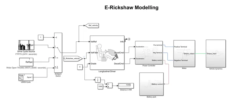
The simulink model is created by using the powertrain blocksets.
The main blocks used are
- Drive cycle source
- multi port switch
- Longitudinal Driver
- Controlled PWM Voltage
- H-Bridge
- DC motor
- Simple gear
- Tire
- Vehicle body
- Dashboard blocks
Drive Cycle:
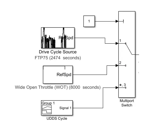
Drive cycle source block from powertrain blockset is selected for the input. 3 drive cycle is selected
- FTP75 drive cycle [2474 seconds] (The FTP (Federal Test Procedure) heavy-duty transient cycle is used for regulatory emission testing of heavy-duty on-road engines in the United States)
- Wide Open throttle cycle [8000 secs] (modified for Vehicle travelling for 100km range for constant speed of 45 kmph) as given in objective
- UDDS cycle [1370 secs] (Urban Dynamometer Driving Schedule (UDDS) driving cycle is a typical urban driving cycle with average speed of 31.51km/h and has frequent braking and acceleration.)
Multi port switch is used to switch between these 3 cycles with selection of the drive cycle using the constant block of the input port.
LONGITUDINAL DRIVER:
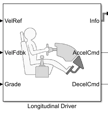
Longitudinal driver block is the default driver block in the powertrain blocksets It will used as controller for generating normalized acceleration and braking commands based on reference and feedback velocities.
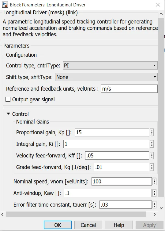
It has the inuilt PI-controller.The below image shows the block parameters.
The input to the longitudinal driver block is Velocity reference,feedback velocity and grade angle and the output we get from this block is Acceleration and Braking commands and the information.
POWER CONTROLLER:
Here I constructed the power controller as a subsystem which consist of controlled voltage sources,Controlled PWM voltages,H bridge circuit for controlling the DC motor and solver confirugation block for calculation.
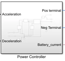
The input to this subsystem in Acceleration and Braking commands and current from battery pack and the output is Terminals for the motor connection.
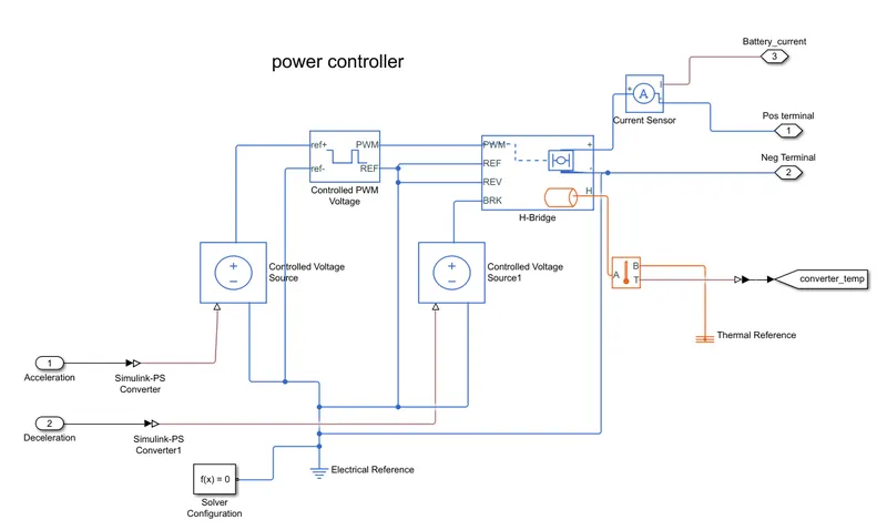
1.Controlled voltage source:
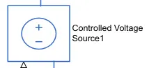
controlled voltage source is given to create the PWM signals for controlling the motor.
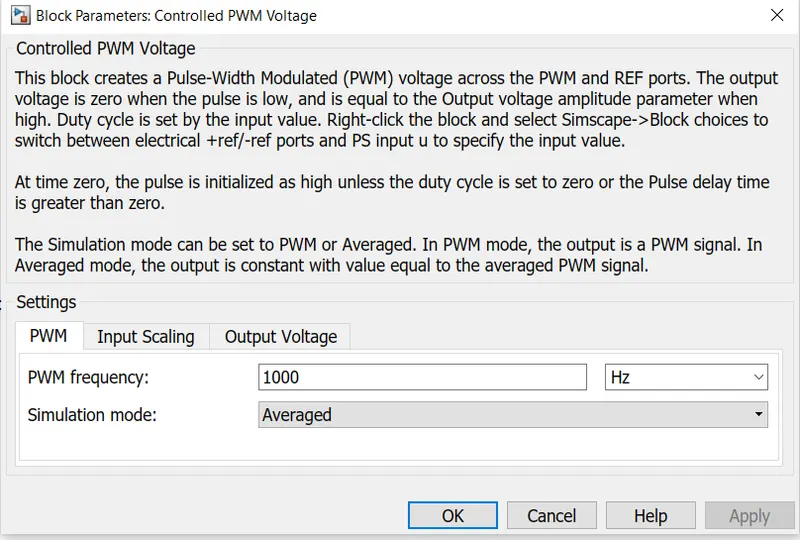
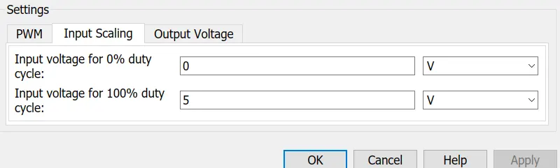
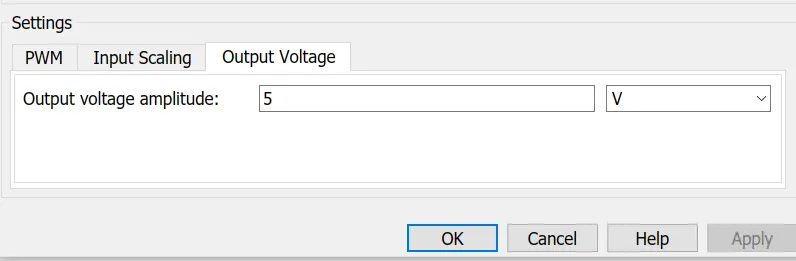
2. Controlled PWM Voltage:
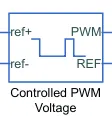
This block creates a Pulse-Width Modulated (PWM) voltage across the PWM and REF ports. The output voltage is zero when the pulse is low, and is equal to the Output voltage amplitude parameter when high. Duty cycle is set by the input value.
The block parameters selected are given below:
3. H-BRIDGE:
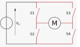
A H-bridge is an electronic circuit that switches the polarity of a voltage applied to a load. These circuits are often used in robotics and other applications to allow DC motors to run forwards or backwards.
The use of H-Bridges in DC Motor control is simple and an easy way to control the direction and speed of a DC motor. The real challenge lies in choosing those Integrated circuits and power supply that are rated to handle the voltage and current the motor would draw.
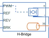
This block represents an H-bridge motor drive. The block can be driven by the Controlled PWM Voltage block in PWM or Averaged mode. In PWM mode, the motor is powered if the PWM port voltage is above the Enable threshold voltage. In Averaged mode, the PWM port voltage divided by the PWM signal amplitude parameter defines the ratio of the on-time to the PWM period. Using this ratio and assumptions about the load, the block applies an average voltage to the load that achieves the correct average load current. The Simulation mode parameter value must be the same for the Controlled PWM Voltage and H-Bridge blocks.
If the REV port voltage is greater than the Reverse threshold voltage, then the output voltage polarity is reversed. If the BRK port voltage is greater than the Braking threshold voltage, then the output terminals are short circuited via one bridge arm in series with the parallel combination of a second bridge arm and a freewheeling diode.Voltages at ports PWM, REV and BRK are defined relative to the REF port.
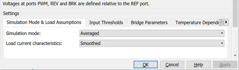
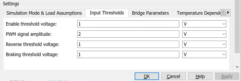
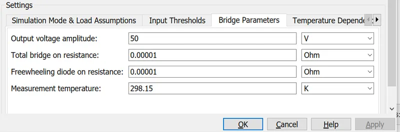
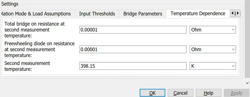
Parameters of the H-Bridge block:
simulation mode selected to averaged and smoothed for both PWM control source and H-Bridge and the threshold voltages are given and output voltage amplitude is given as 50V and the temperature resistand and initial temperature 298.15 K is given.
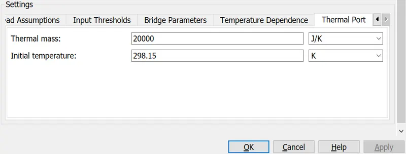
Thermal port of the motor controller:
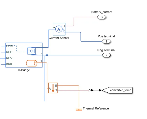
Temperature sensor block is added to measure the temperature of the power controller while working and the current sensor block is used to measure the current from battery pack
The positive and negative terminal are the two blocks which is the output of the power controller subsystem these terminals are given to the dc motor.
DC MOTOR:
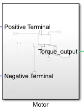
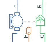
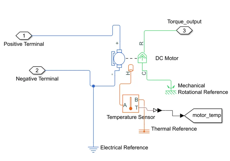
DC motor subsystem consist of DC motor (PM Brushed type),and the temperature sensor to measure the Motor temperature.
Here,we selected the motor with below parameters:
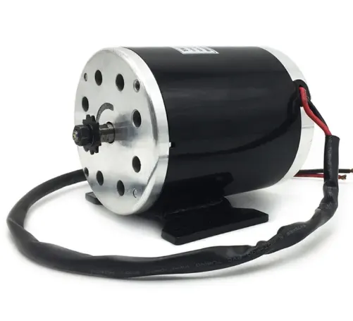
MY1020 48V 2000W Brushed DC Motor
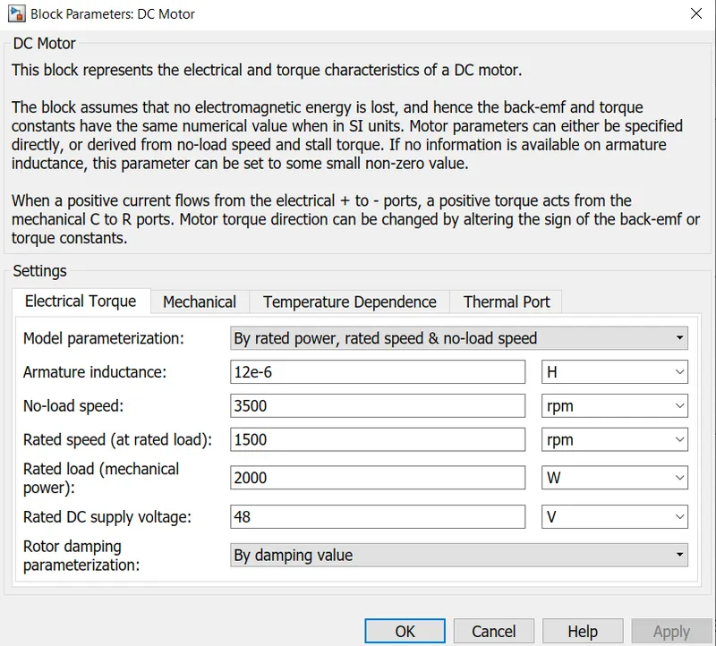
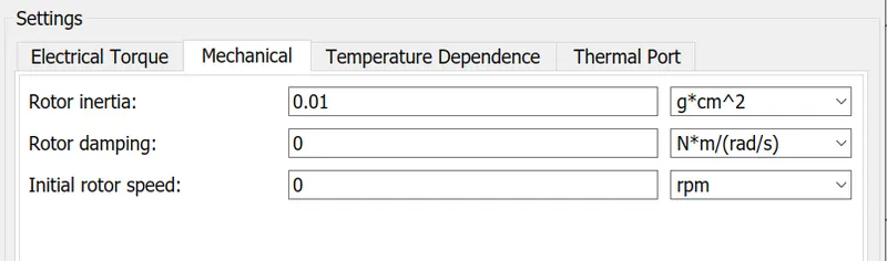
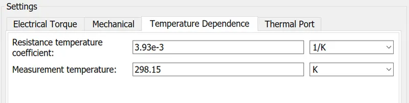
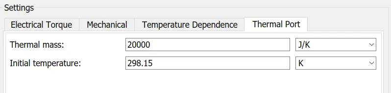
The motor parameters rate speed 1500 rpm,no load speed 3500 rpm,2KW power,48V supply voltage is given as dc motor block parameters, the output torque from dc motor shaft is coupled with simple gear of the E-rickshaw.
VEHICLE DYNAMICS:

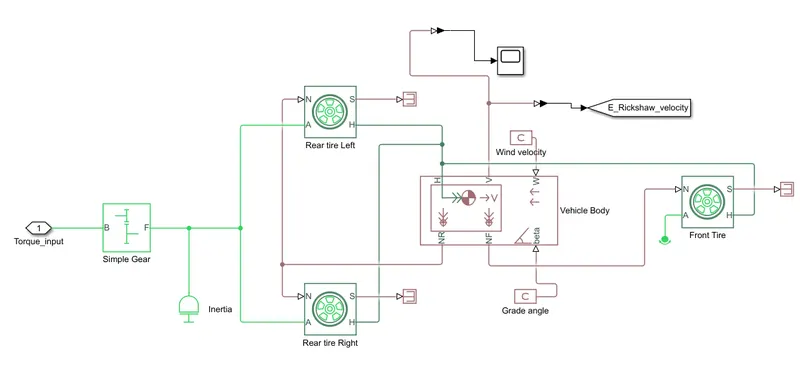
Vehicle dynamics subsystem consist of vehicle body block, front and rear(left and right) tire, simple gear blocks.
Simple Gear:
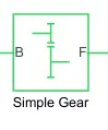
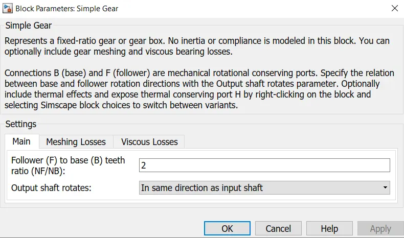
Here, simple gear is used for transmission with follower to base ratio - 2,output shaft rotates with same direction of input shaft.
Tire:
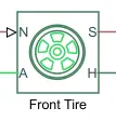
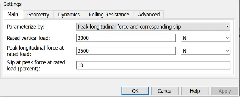
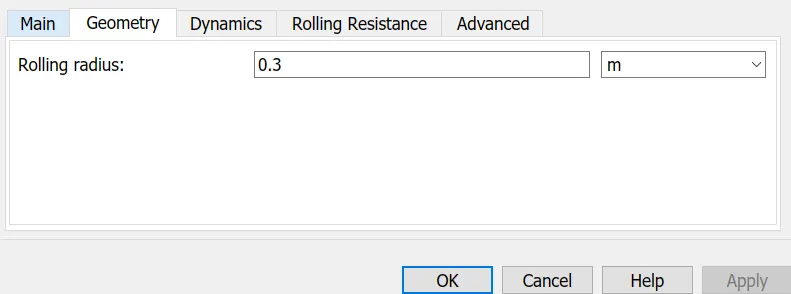
Represents the longitudinal behavior of a highway tire characterized by the tire Magic Formula. The block is built from Tire-Road Interaction (Magic Formula) and Simscape Foundation Library Wheel and Axle blocks. Optionally, the effects of tire inertia, stiffness, and damping can be included.
Connection A is the mechanical rotational conserving port for the wheel axle.
Connection H is the mechanical translational conserving port for the wheel hub through which the thrust developed by the tire is applied to the vehicle.
Connection N is a physical signal input port that applies the normal force acting on the tire. The force is considered positive if it acts downwards.
Connection S is a physical signal output port that reports the tire slip.
Optionally expose physical signal port M by setting Parameterize by to Physical signal Magic Formula coefficients. Physical signal port M accepts a four element vector corresponding to the B, C, D, and E Magic Formula coefficients.
VEHICLE BODY:
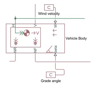
Represents a two-axle vehicle body in longitudinal motion. The block accounts for body mass, aerodynamic drag, road incline, and weight distribution between axles due to acceleration and road profile. The vehicle can have the same or a different number of wheels on each axle. Optionally include pitch and suspension dynamics or additional variable mass and inertia. The vehicle does not move vertically relative to the ground.
Connection H is the mechanical translational conserving port associated with the horizontal motion of the vehicle body. The resulting traction motion developed by tires should be connected to this port.
Connections V, NF, and NR are physical signal output ports for vehicle velocity and front and rear normal wheel forces, respectively. Wheel forces are considered positive if acting downwards.
Connections W and beta are physical signal input ports corresponding to headwind speed and road inclination angle, respectively.
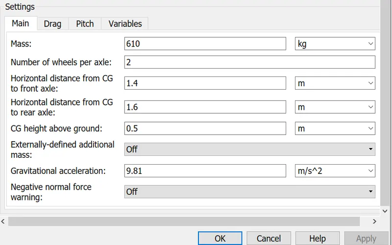
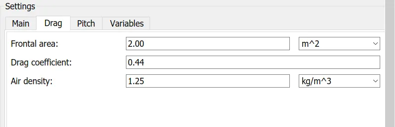
Here, we given the weight of the vehicle as 610 kg,no of wheels per axle 2,Frontal area 2m^2,Drag coefficient Cd=0.44,Air density as 1.25 kg/m^3.
wind velocity is given as 1m/s and beta grade angle is given as 2 degree using the PS-constant blocks.
The vehicle velocity which is the output of the vehicle body block is get from the connection V, which is the E-Rickshaw velocity. which is given to the goto block and used as feedback velocity for the longitudinal driver block.
BATTERY PACK:
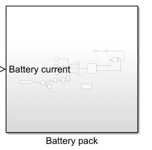
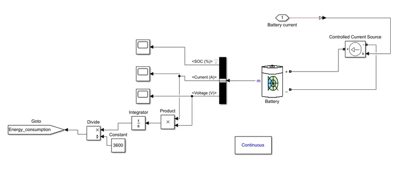
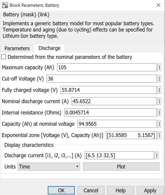
The battery pack subsystem consist of Battery model(lithium ion),controlled current source,and energy consumption conversion blocks and scope blocks for soc,current and voltage.
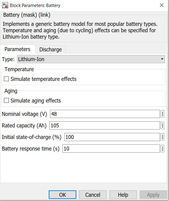
The below battery parameters are selected for the model:

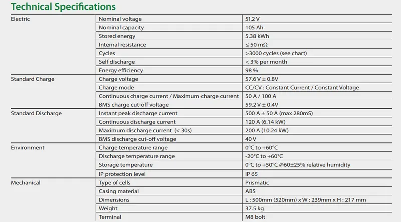
Characteristics of battery pack:
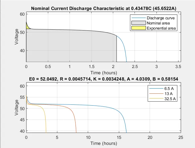
Controlled current source is given to the lithium ion battery pack and the soc,current and voltage is taken from the battery output.Energy consumption is calculated by integrating the power (VI).
Result Blocks:
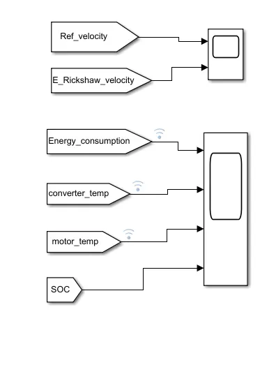
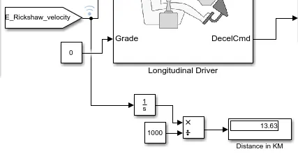
Results are obtained from the scope blocks by using the Goto and From blocks and the distance covered is measured using the integrtor and divide block, where the distance is meters is converted into Km.
Distance measurement
DASHBOARD BLOCKS:
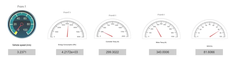
Dashboard blocks are given to show the results of velocity of the vehicle,energy consumption,motor temperature,controller temperature and soc % of the battery using the custom gauge,half gauge and display blocks from dashboard.
RESULTS:
We have model the E-rickshaw for the three different drive cycle,the results of the simulation of E-rickshaw is observed,analysed and plotted below.
Model 1:
FTP75 drive cycle [2474 seconds]
(The FTP (Federal Test Procedure) heavy-duty transient cycle is used for regulatory emission testing of heavy-duty on-road engines in the United States)
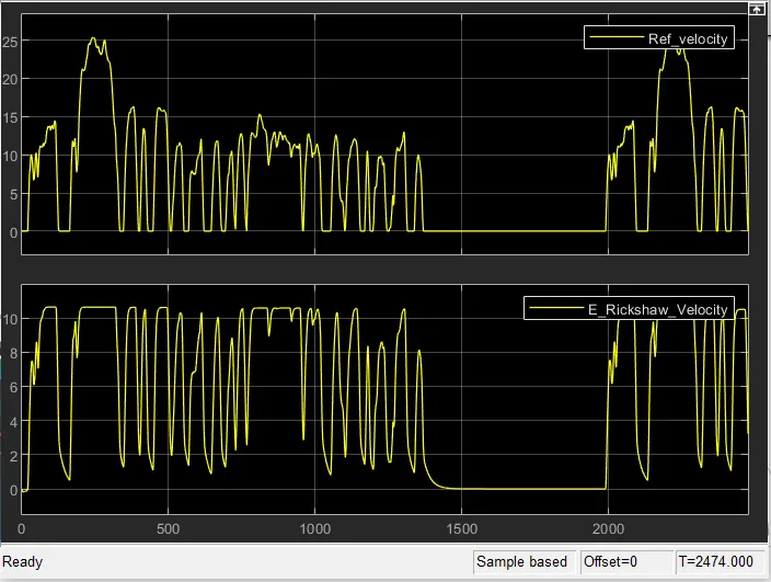
Drive cycle velocity vs Actual velocity:
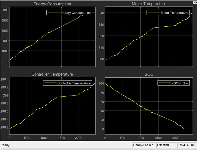
Energy Consumption,Motor Temperature,Controller Temperature and SOC of battery results:
Dashboard results:
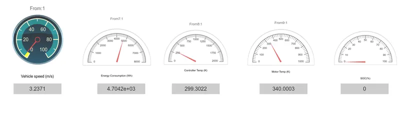
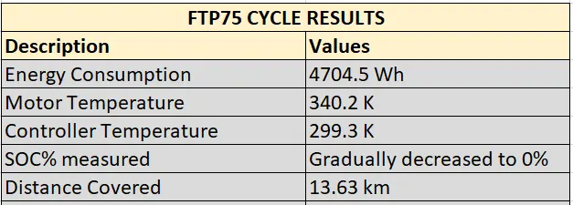
The simulation is run for 2474 secs, Here we observed that
The output velocity is nearly following the reference velocity which is drive cycle velocity,we can improve the output velocity by PID tuning.
Ther energy consumption is upto 4704 Wh
The motor temperature is rise to 340.2 K and
the Controller temperature is rise to 299.3 K and temperature is maintained at safe level.
soc is gradually decreased to 0% because the capacity of the battery selected is 105 Ah if we increase the battery capacity we can get the soc at appropriate levels and regenerative braking will maintain the SOC. after 2100 secs the battery get drained.
and the distance covered is 13.63 km.
Model 2:
Wide Open throttle cycle [8000 secs]
(modified for Vehicle travelling for 100km range for constant speed of 45 kmph) as given in objective.
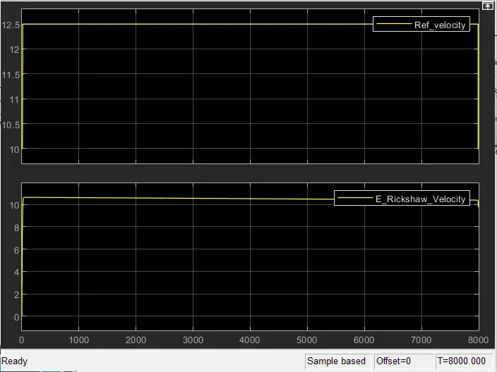
Drive cycle velocity vs Actual velocity:
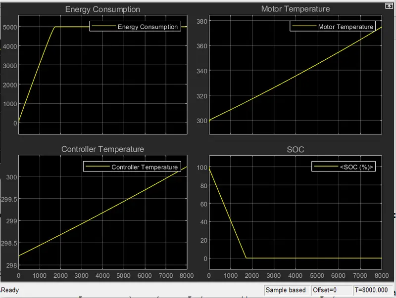
Energy Consumption,Motor Temperature,Controller Temperature and SOC of battery results:
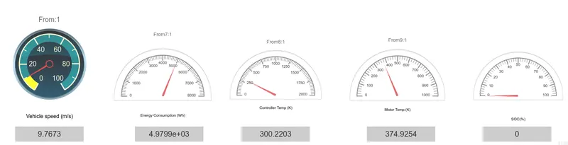
Dashboard results:
The simulation is run for 8000 secs, as per the objective
To cover the distance of 100 km at 45kmph constant speed which is 12.5m/s, 8000 secs is needed.
Here we observed that
The output velocity is nearly following the reference velocity which is drive cycle velocity,we can improve the output velocity by PID tuning.
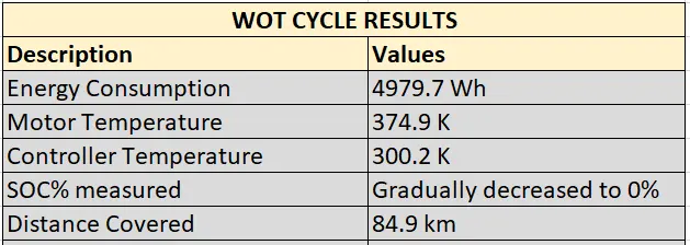
Ther energy consumption is upto 4979.7 Wh
The motor temperature is rise to 374.9 K and
the Controller temperature is rise to 300.3 K and
SOC is gradually decreased to 0% because the capacity of the battery selected is 105 Ah if we increase the battery capacity we can get the soc at appropriate levels and regenerative braking will maintain the SOC. after 1800 secs the battery get drained because for 45kmph constant speed the more power is needed so the battery gets drained quickly.
and the distance covered is 84.9 km which is less than 100 km because of motor and controller efficiencies.
Model 3:
UDDS cycle [1370 secs]
(Urban Dynamometer Driving Schedule (UDDS) driving cycle is a typical urban driving cycle with average speed of 31.51km/h and has frequent braking and acceleration)
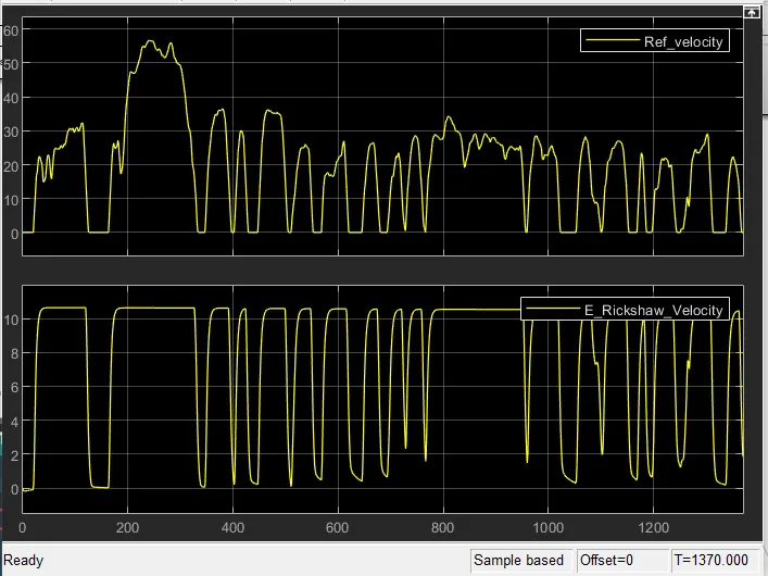
Drive cycle velocity vs Actual velocity:
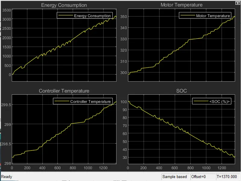
Energy Consumption,Motor Temperature,Controller Temperature and SOC of battery results:
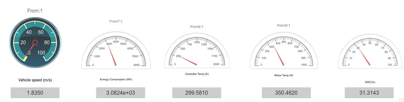
Dashboard results:
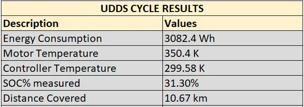
The simulation is run for 1370 secs,Here we observed that
The output velocity is nearly following the reference velocity which is drive cycle velocity,we can improve the output velocity by PID tuning.
Ther energy consumption is upto 3082.4 Wh
The motor temperature is rise to 350.4 K and
the Controller temperature is rise to 299.5 K and
SOC is gradually decreased to 31.3% because the capacity of the battery selected is 105 Ah if we increase the battery capacity we can maintain the soc at appropriate levels and regenerative braking will maintain the SOC.
and the distance covered is 10.67 km.
CONCLUSION:
The MATLAB model of Electric Rickshaw is modeled using SIMULINK and PM brushed type motor is selected for the model.
Some parameters of Motor and Controller are assumed and excel sheet is prepared for the inputs and assumptions.
For the three driving cycles
1.FTP75 cycle
2.WOT cycle
3. UDDS cycle
the simulation is done and the results of energy consumption,rise in motor and controller temperatures and SOC are observed,analyzed and plotted.
For the driving cycle of vehicle covering the 100km at constant speed of 45 kmph is modeled using WOT cycle and the results of energy consumption,rise in motor and controller temperatures and SOC are observed and plotted.
We can conclude that model of E-rickshaw is succesfully created and simulation is done for given drive cycle inputs and desired results are obtained.The model now is giving the results which is nearly following the given inputs, if we adjust some parameters and tuning the driver model using the PID controllers we can improve the model and efficiency of the E-Rickshaw model.
REFERENCES:
https://en.wikipedia.org/wiki/Electric_rickshaw
https://www.mahindraelectric.com/vehicles/treo-electric-auto/
https://skill-lync.com/student-projects/final-project-electric-rickshaw-modelling-34
https://www.electricmotorsport.com/ev-parts/motors/brushed-motors?limit=all
https://en.wikipedia.org/wiki/Brushed_DC_electric_motor
Thank you
Submitted BY
B.Riyaz
04/10/2022