Final Project: Electric Rickshaw modelling
ELECTRIC RICKSHAW
Electronic rickshaws have now transitioned from being a market entrant in the automobile industry of India to a leading short-distance transport solution.This segment gained popularity between 2015 and 2018. Although this segment is dominated by a host of unorganized players, established manufacturers have also identified its growth opportunities and are expected to foray into the segment.
These rickshaws have a mild steel tubular chassis, consisting of three wheels with a differential mechanism at the rear wheels. The motor is a brushless DC motor. The electrical system used in Indian versions is 48V and in Bangladesh is 60V. The body design from most popular Chinese version is of very thin iron or aluminum sheets. Bodies made of fiberglass are also popular because of their strength and durability, resulting in low maintenance. Body design is varied from load carriers, passenger vehicles with no roof, to full body with windshield for drivers comfort.It consists of a controller unit.[clarification needed] They are sold on the basis of voltage supplied and current output, also the number of mosfet (metal oxide field effect transistors) used. The vehicle's batteries are typically lead acid with a lifespan of 6–12 months. Deep cycle batteries designed for electric vehicles are rarely used. Weight of the electric car has also been a recurring design difficulty in them.
One of the first attempts to design electric rickshaws was done by Nimbkar Agricultural Research Institute in late 1990s. In India, these e-rickshaws are widely spread all over the country, starting to gain popularity around 2011. The design is now much different from cycle rickshaws.Today, e-rickshaws play a vital role in providing livelihood to people in India. Due to their low cost and high efficiency, they are accepted on the Indian streets, but government policies have been threatening the e-rickshaw and banned its use in the capital city Delhi, but failed to put them off the streets. E-rickshaws are still rising in number and widely used in Delhi and other parts of India. In Delhi, as per government official's figures in April 2012, their number was over 100,000.Electric rickshaw in Meerut, Uttar Pradesh, India
E-rickshaw law in India
Initially e-rickshaws were unregulated by any central law in India. However, the Delhi High Court, banned running of e-rickshaws in Delhi on 31 July 2014 over safety concerns raised through a public interest litigation.In a rally held for regularization of e rickshaws in Delhi transport minister Nitin Gadkari said that "municipal corporations would regularize e-rickshaws by registering them for a fee of just ₹100. After registering the e-rickshaw, corporations will have to issue identity cards to drivers so they can earn their livelihood easily."Once the policy was in place, the corporation, along with traffic police, would have fix the amount of fine to be imposed for violation of the policy.However, the policy was never implemented. Certain states like Tripura had regularized the e-rickshaws through municipal bylaws or through state legislation. In March 2015, the Indian Parliament passed an amendment to the Motor Vehicles (Amendment) Bill, 2015 legalizing e-rickshaws. By July 2015, battery rickshaws are available for travel in many cities, and are now certified to ply with Registration No. plate by R.T.O. with insurance.
COMPONENTS:
Major component used are as below:
- Wheel/tier
- Vehicle body
- Battery system
- Transmission Sytem
- Power Converter
- Motor Controller
Main Simulation:
The below image shows the simulink design of complete AUTO /RICKSHAW EV. By using the above mention block the design is made.The Drive cycle block is used to give input to the vehicle & accleration / deceration inputs are given.
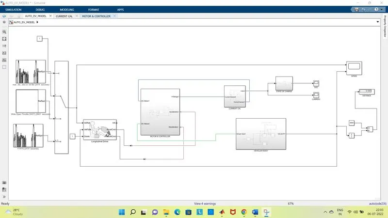
Now let us look in details each block used in Simulation and their paramaters:
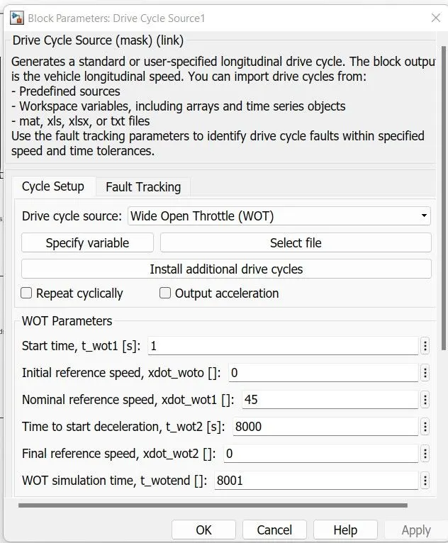
45 KMPH DRIVE CYCLE:
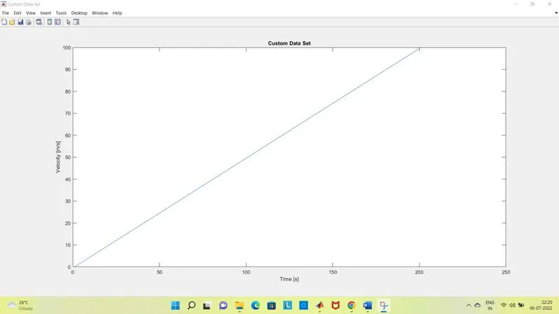
CUSTOM DRIVE CYCLE:
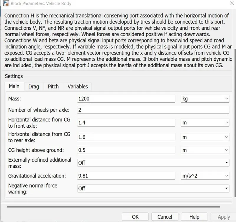
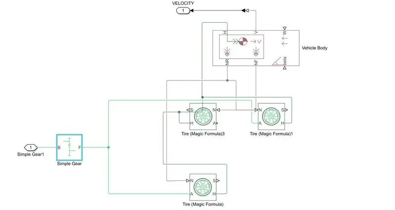
VEHICLE BODY:
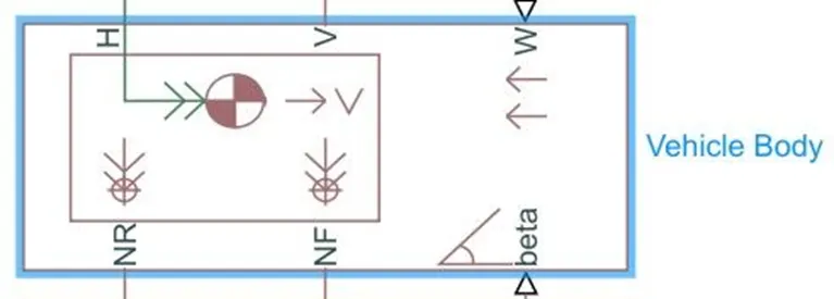
Represents a two-axle vehicle body in longitudinal motion. The block accounts for body mass, aerodynamic drag, road incline, and weight distribution between axles due to acceleration and road profile. The vehicle can have the same or a different number of wheels on each axle. Optionally include pitch and suspension dynamics or additional variable mass and inertia. The vehicle does not move vertically relative to the ground.
Connection H is the mechanical translational conserving port associated with the horizontal motion of the vehicle body. The resulting traction motion developed by tires should be connected to this port. Connections V, NF, and NR are physical signal output ports for vehicle velocity and front and rear normal wheel forces, respectively. Wheel forces are considered positive if acting downwards. Connections W and beta are physical signal input ports corresponding to headwind speed and road inclination angle, respectively. If variable mass is modeled, the physical signal input ports CG and M are exposed. CG accepts a two- element vector representing the x and y distance offsets from vehicle CG to additional load mass CG. M represents the additional mass. If both variable mass and pitch dynamics are included, the physical signal port J accepts the inertia of the additional mass about its own CG.
The parameters selected are as below:
TIRE:
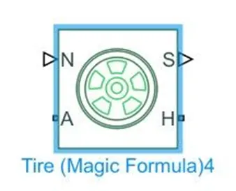
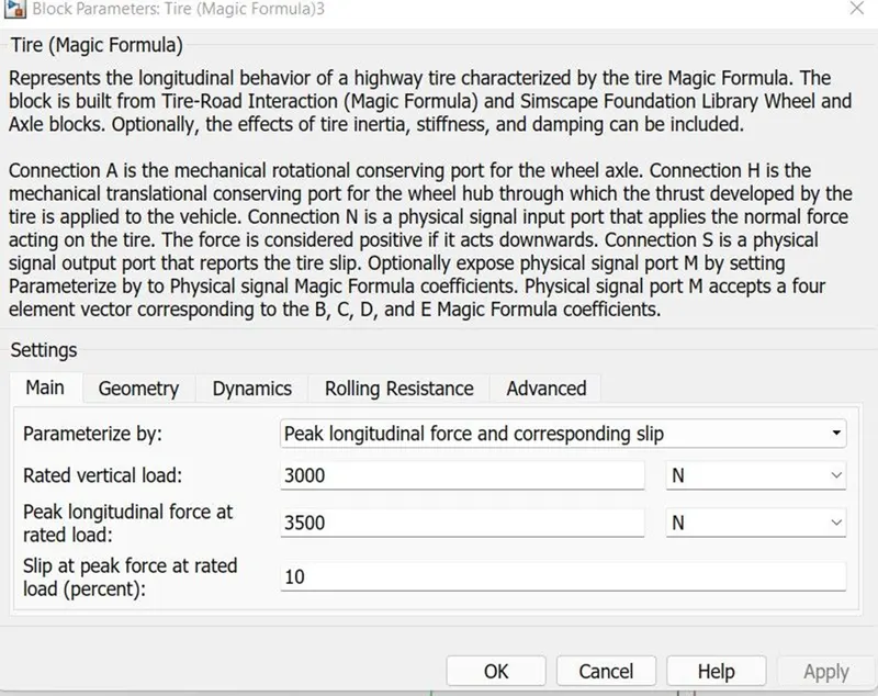
Represents the longitudinal behavior of a highway tire characterized by the tire Magic Formula. The block is built from Tire-Road Interaction (Magic Formula) and Simscape Foundation Library Wheel and Axle blocks. Optionally, the effects of tire inertia, stiffness, and damping can be included.
Connection A is the mechanical rotational conserving port for the wheel axle. Connection H is the mechanical translational conserving port for the wheel hub through which the thrust developed by the tire is applied to the vehicle. Connection N is a physical signal input port that applies the normal force acting on the tire. The force is considered positive if it acts downwards. Connection S is a physical signal output port that reports the tire slip. Optionally expose physical signal port M by setting Parameterize by to Physical signal Magic Formula coefficients. Physical signal port M accepts a four element vector corresponding to the B, C, D, and E Magic Formula coefficients.
The parameters selected are as below:
SIMPLE GEAR:
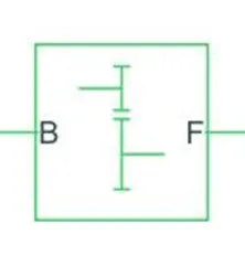
Represents a fixed-ratio gear or gear box. No inertia or compliance is modeled in this block. You can optionally include gear meshing and viscous bearing losses.
Connections B (base) and F (follower) are mechanical rotational conserving ports. Specify the relation between base and follower rotation directions with the Output shaft rotates parameter. Optionally include thermal effects and expose thermal conserving port H by right-clicking on the block and selecting Simscape block choices to switch between variants.
VEHICLE BODY SUBSYSTEM:
By using all above blocks a susbsytem is created. All the component are connected to their respective terminal and whole system is created as a subsytem of EV which is as below.
STATE OF CHARGE:
The below system shows the calcultion of SOC:
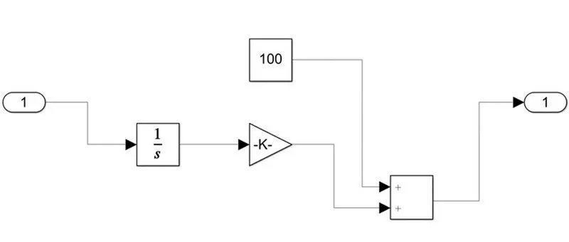
The blocks used are:
- Integrator:Continuous-time integration of the input signal.
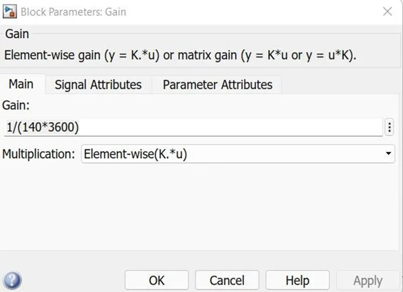
- Gain:Element-wise gain (y = K.*u) or matrix gain (y = K*u or y = u*K).
- Add:
Add or subtract inputs. Specify one of the following:
- a) character vector containing + or - for each input port, | for spacer between ports (e.g. ++|-|++)
- b) scalar, >= 1, specifies the number of input ports to be summed.
When there is only one input port, add or subtract elements over all dimensions or one specified dimension
- Constant: To take refrence as battery 100% charge 140Ah And 3600 sec.
Futher this block output is connected to the scope and the SOC is observed.
MOTOR CONTROLLER SUBSYSTEM:
The major blocks used in the subsystem are as below:
- DC motor
- Controlled PWM Voltage.
- H-Bridge
Now let us look at each block in details:
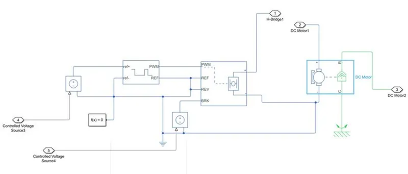
DC MOTOR:
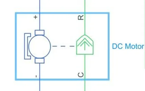
This block represents the electrical and torque characteristics of a DC motor.
The block assumes that no electromagnetic energy is lost, and hence the back-emf and torque constants have the same numerical value when in SI units. Motor parameters can either be specified directly, or derived from no-load speed and stall torque. If no information is available on armature inductance, this parameter can be set to some small non-zero value.
When a positive current flows from the electrical + to - ports, a positive torque acts from the mechanical C to R ports. Motor torque direction can be changed by altering the sign of the back-emf or torque constants.
The parameters are kept as below:
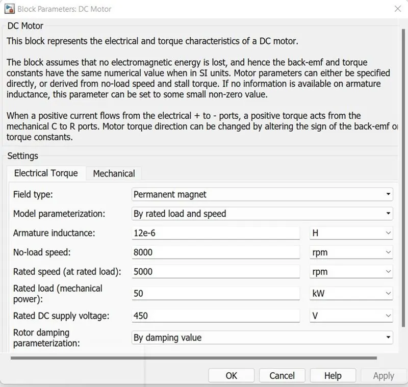
The motors used in EV are huge hence 50KW is selected with Rated speed of 5000 rpm.
The DC motor is connected to Mechanical Ref:
This block represents a mechanical rotational reference point, that is, a frame or a ground. Use it to connect mechanical rotational ports that are rigidly affixed to the frame (ground).

H-BRIDGE:
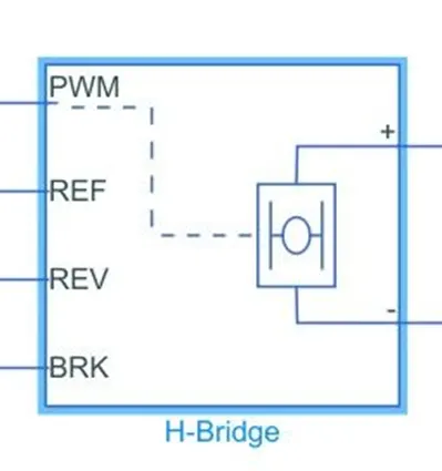
This block represents an H-bridge motor drive. The block can be driven by the Controlled PWM Voltage block in PWM or Averaged mode. In PWM mode, the motor is powered if the PWM port voltage is above the Enable threshold voltage. In Averaged mode, the PWM port voltage divided by the PWM signal amplitude parameter defines the ratio of the on-time to the PWM period. Using this ratio and assumptions about the load, the block applies an average voltage to the load that achieves the correct average load current. The Simulation mode parameter value must be the same for the Controlled PWM Voltage and H-Bridge blocks.
If the REV port voltage is greater than the Reverse threshold voltage, then the output voltage polarity is reversed. If the BRK port voltage is greater than the Braking threshold voltage, then the output terminals are short circuited via one bridge arm in series with the parallel combination of a second bridge arm and a freewheeling diode. Voltages at ports PWM, REV and BRK are defined relative to the REF port.
If exposing the power supply connections, the block only supports PWM mode.
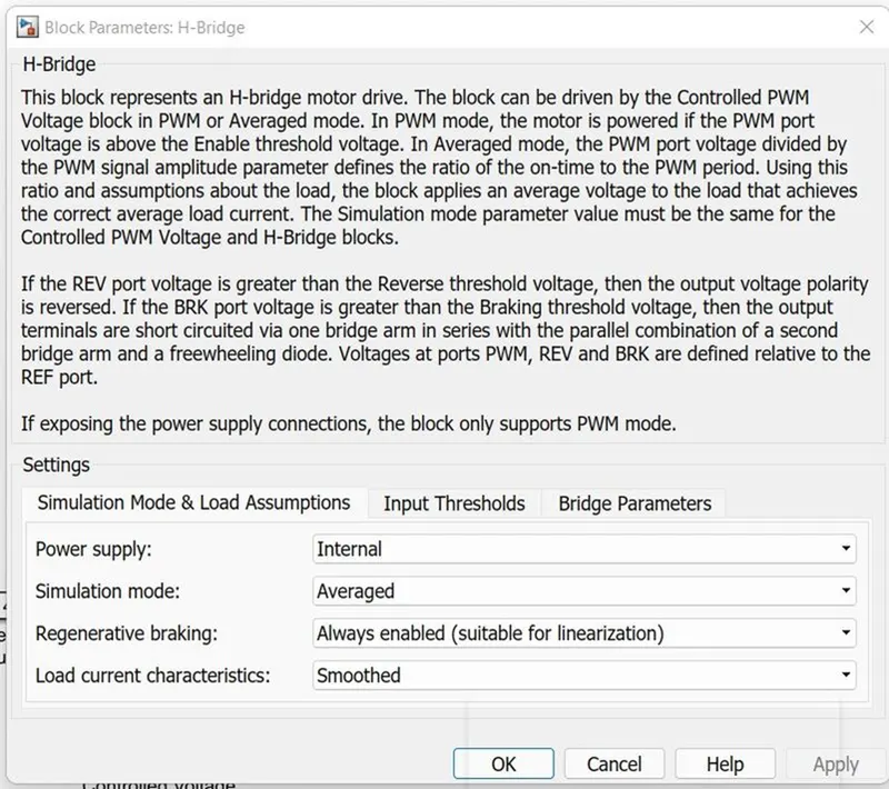
The Simulation mode is kept averaged for faster simulation & the regenerative braking is enabled.
CONTROLLED PWM VOLTAGE:
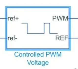
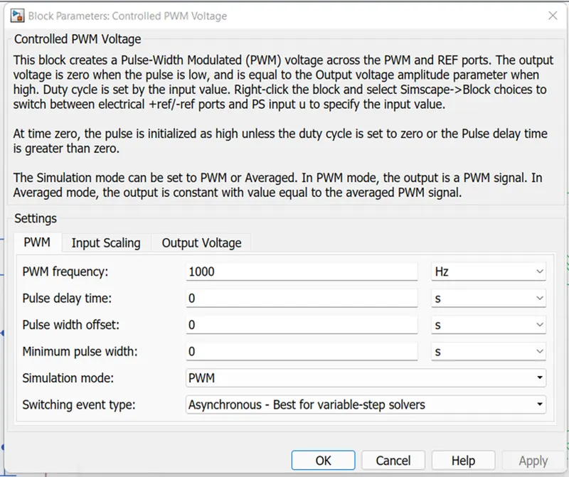
This block creates a Pulse-Width Modulated (PWM) voltage across the PWM and REF ports. The output voltage is zero when the pulse is low, and is equal to the Output voltage amplitude parameter when high. Duty cycle is set by the input value. Right-click the block and select Simscape->Block choices to switch between electrical +ref/-ref ports and PS input u to specify the input value.At time zero, the pulse is initialized as high unless the duty cycle is set to zero or the Pulse delay time is greater than zero.The Simulation mode can be set to PWM or Averaged. In PWM mode, the output is a PWM signal. In Averaged mode, the output is constant with value equal to the averaged PWM signal.
CONTROLLED VOLTAGE SOURCE:
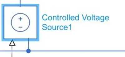
The block represents an ideal voltage source that is powerful enough to maintain the specified voltage at its output regardless of the current passing through it. The output voltage is V = Vs, where Vs is the numerical value presented at the physical signal.
CURRENT CALCULATION:
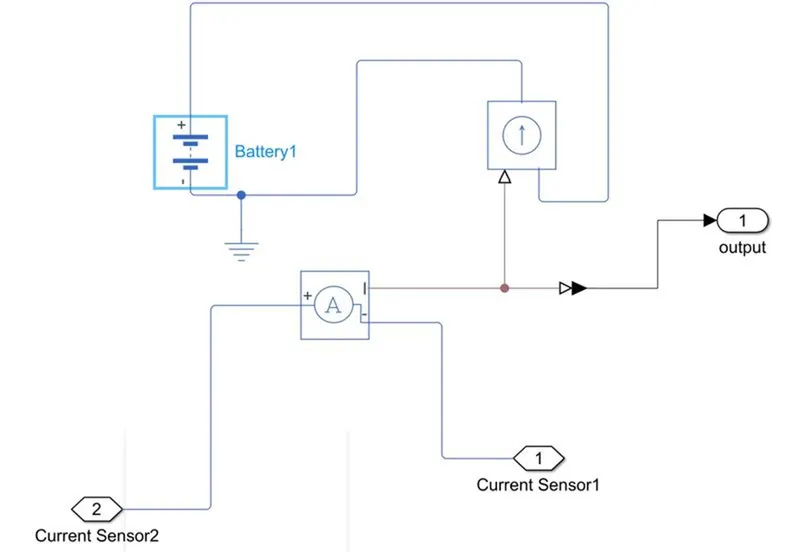
BATTERY :
This block models a battery. If you select Infinite for the Battery charge capacity parameter, the block models the battery as a series internal resistance and a constant voltage source. If you select Finite for the Battery charge capacity parameter, the block models the battery as a series internal resistance plus a charge-dependent voltage source defined by:
V = Vnom*SOC/(1-beta*(1-SOC))
where SOC is the state of charge and Vnom is the nominal voltage. Coefficient beta is calculated to satisfy a user-defined data point [AH1,V1].
CURRENT SENSOR:
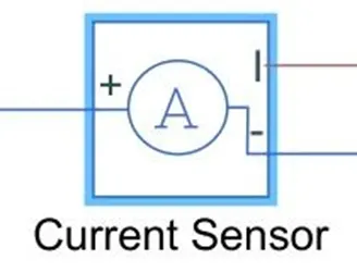
The block represents an ideal current sensor, that is, a device that converts current measured in any electrical branch into a physical signal proportional to the current.
Connections + and - are conserving electrical ports through which the sensor is inserted into the circuit. Connection I is a physical signal port that outputs current value.
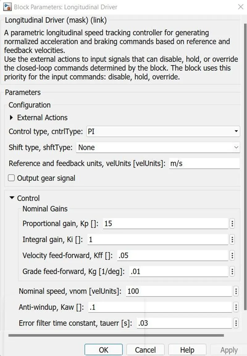
LONGITUDINAL DRIVER:
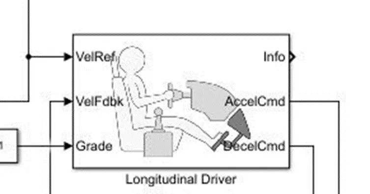
A parametric longitudinal speed tracking controller for generating normalized acceleration and braking commands based on reference and feedback velocities.
Use the external actions to input signals that can disable, hold, or override the closed-loop commands determined by the block. The block uses this priority for the input commands: disable, hold, override.
DRIVE CYCLE BLOCK:
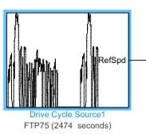
Generates a standard or user-specified longitudinal drive cycle. The block output is the vehicle longitudinal speed. You can import drive cycles from:
- Predefined sources
- Workspace variables, including arrays and time series objects
- mat, xls, xlsx, or txt files
Use the fault tracking parameters to identify drive cycle faults within specified speed and time tolerances.
RESULTS:
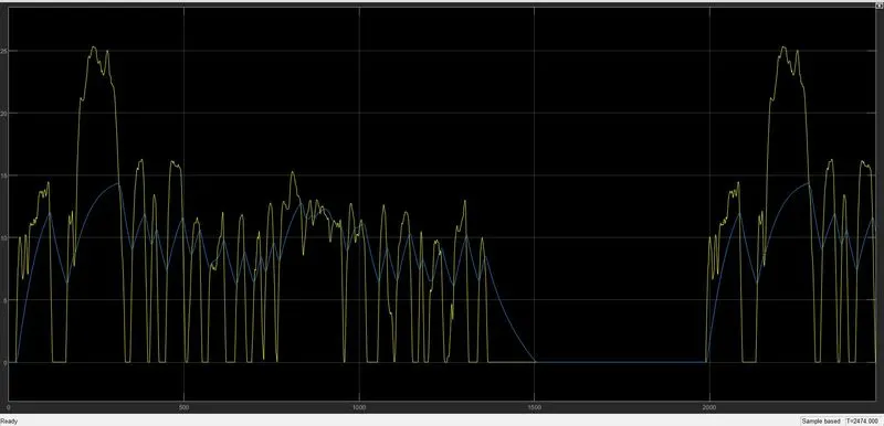
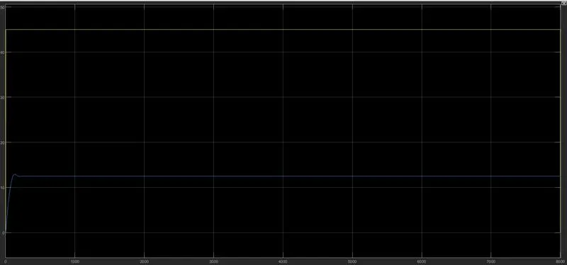
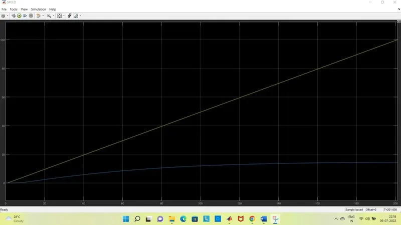
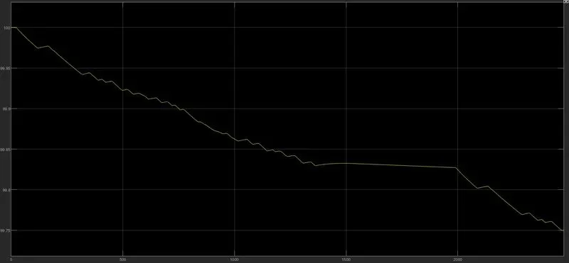
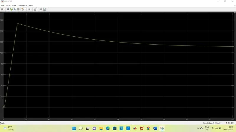
The above whole model is simulated by using the FTP75 cycle. According to that the simulation time is set.The Output obtain are in scope which are SOC,Current,Speeed and Distance in Display.
SPEED SCOPE:
FTP 75 DRIVE CYCLE
45KMPH
CUSTOM DRIVE CYCLE:
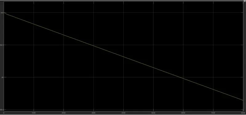
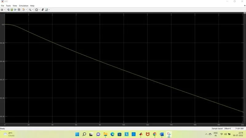
SOC:
FTP 75 DRIVE CYCLE
45 KMPH
CUSTOM CYCLE:
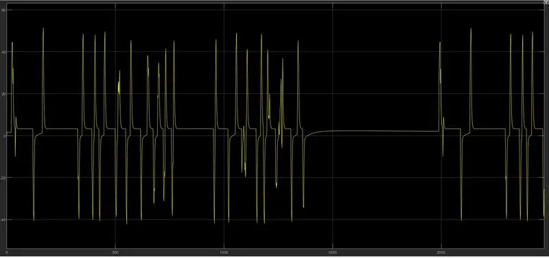
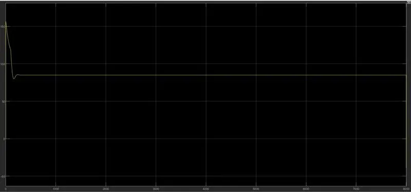
CURRENT:
FTP 75 DRIVE CYCLE
45 KMPH
CUSTOM CYCLE
DISTANCE:
The total distance travel by the AUTO EV by following the above drive cycle is FTP CYCLE 5 km, 45 KMPH 0.19 KMPH, custom drive cycle 1.8 km
CONCLUSION:
| DRIVE CYCLE | DISTANCE | SOC | MAX CURRENT | MIN CURRENT |
| FTP 75 | 5 | 90 | 70 | 5 |
| 45 KMPH | 0.19 | 98 | 130 | 95 |
| CUSTOM | 1.8 | 96 | 150 | 110 |
The AUTO EV model is created by using the simulink blocks and powertrain.The model is simulated using FTP75 drive cycle with simukation time of 2474 sec.The simulations shows the output of SOC which observed during the simulation is 100% and at end 90% of the cycle. By completing the cycle EV travelled 20 km.The model was enabled with the regenrative braking which helps the battery to charge during braking.
The model is simulated using 45 kmph drive cycle with simukation time of 8000 sec.The simulations shows the output of SOC which observed during the simulation is 100% and at end 98% of the cycle. By completing the cycle EV travelled 0.2 km.The model was enabled with the regenrative braking which helps the battery to charge during braking.
The model is simulated using custom drive cycle with simukation time of 201 sec.The simulations shows the output of SOC which observed during the simulation is 100% and at end 96% of the cycle. By completing the cycle EV travelled 1.8 km.The model was enabled with the regenrative braking which helps the battery to charge during braking.