Week -2
1.Simulink model of Doorbell using solenoid block
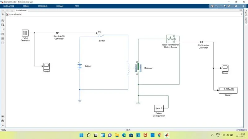
For sloving the above question following blocks where used listed below:
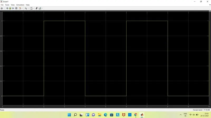
- Pulse Generator - This is used to generate pulse which would actuate the coil for 2 sec and off for 2 sec the process will go on uas per input feeded in the generator.
- Scope 1 - The pulse generator output would be seen in this scope by which we can adjust the pulses as needed.
- Simulink-PS converter & PS - Simulink converter - this block would convert the simulink to ps and vice versa.
- Battery - battery is used to supply the voltage required for solenoid coil to actuate.
- Switch - basically this would pass the supply and by help of pulse generator the switch is on/off.
- Solenoid Coil - when electrical circuit gets completed the coil will act as an electromagnet and the plunger gets actuated which would move the plunger and bell ring.
- Electrical & Mechanical refrence - they provide grounding reference for electrical and mechanical circuit respectively.
- Ideal Transaltional Motion sensor - this block replicated the bell and gives the output.
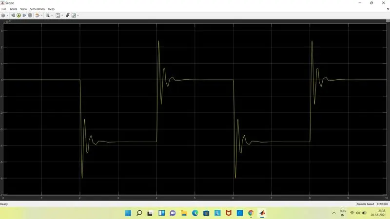
- Scope - the output graph of bell is viwed in this scope.
Outputs and Model pictures are attached below:-
- Pluse generator input
- Simulink & Simcape model
- Bell Ring output
2. Use a thermistor to sense the temperature of a heater & turn on or turn off the fan as per the below conditions:
For sloving the above question following blocks where used listed below:
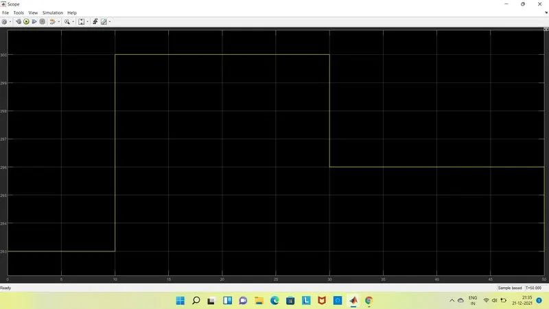
- Repeating Sequence stairs - This block generates the input condition require in this case [ 293 300 300 297 297] with sampling time sec, a scope is added at input to check the condition .
- Simulink-PS converter & PS - Simulink converter - this block would convert the simulink to ps and vice versa.
- Controlled Temperature source - ideal temperature source.
- Thermistor -the combination of thermal and resistor is termed as thermistor
- Electrical & Mechanical refrence - they provide grounding reference for electrical and mechanical circuit respectively.
- Scope - to view the output obtain and for analysing the graph.
Outputs and Model pictures are attached below:-
Input scope-
Full simulink & simscape model -
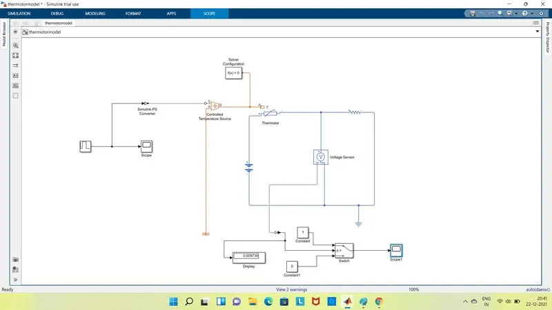
output scope -
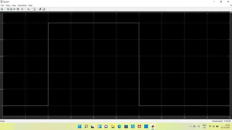
From the output graph we see that the model has performed the task from 1o to 30 sec the temperature goes up and fan is turned on post 30 sec when temperature drops below the fan is off.