Week-6 Challenge: EV Drivetrain
Q1.Which types of power converter circuits are employed in electric and hybrid electric vehicle?
Power Electronic Introduction:
Power electronic technology deals with processing and controlling the flow of electrical energy in order to supply voltages and currents in a form that optimally suited for end user’s requirements.A power electronic converter uses power electronic components such as SCRs, TRIACs, IGBTs, etc. to control and convert the electric power. The main aim of the converter is to produce conditioning power with respect to a certain application
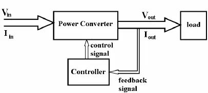
The block diagram of a power electronic converter is shown in figure above. It consist of an electrical energy source, power electronic circuit, a control circuit and an electric load. This converter changes one form of electrical energy to other form of electrical energy.
The power electronic circuit consists of both power part and control part. Power part transfers the energy from source to load and it consists of power electronic switches (SCR or TRIAC), transformers, electric choke, capacitors, fuses and sometimes resistors.
The control circuit or block regulates the elements in the power part of the converter. This block is built with a complex low power electronic circuit that consists of either analog or digital circuit assembly.
Power electronic converters perform various basic power conversion functions. This converter is a single power conversion stage that can perform any of the functions in AC and DC power conversion systems.
Depending on the type of function performed, power electronic converters are categorized into following types.
- AC to DC = Rectifier: It converts AC to unipolar (DC) current
- DC to AC = Inverter: It converts DC to AC of desired frequency and voltage
- DC to DC = Chopper: It converts constant to variable DC or variable DC to constant DC
- AC to AC = Cycloconverter, Matrix converter: It converts AC of desired frequency and/or desired voltage magnitude from a line AC supply.
The detailed of each types are explained below.
- AC TO DC CONVERTER:
A type of converter that changes input AC signal into a DC is known as AC to DC converter. We have already learned in basic electronics that the devices that convert the AC signal into DC signal are known as rectifiers.
AC to DC Converter is further classified as:
Diode Rectifiers: This rectifier circuit changes applied ac input voltage into a fixed dc voltage. Either a single-phase or three-phase ac signal is applied at the input. These are mainly used in electric traction and in electrochemical processes like electroplating along with in battery charging and power supply. These are also used in welding and UPS related services.
Phase Controlled Rectifiers: Unlike diode rectifiers, phase-controlled rectifiers are designed to convert a fixed value of ac signal voltage into a variable dc voltage. Here line voltage operates the rectifier hence these are sometimes known as line commutated ac to dc converters. Similar to diode rectifiers, here also the applied ac signal can be a single-phase or three-phase ac signal. Its major applications are in dc drives, HVDC systems, compensators, metallurgical and chemical industries as well as in excitation systems for synchronous machines.
- DC TO AC CONVERTER:
The devices that are designed to convert the dc signal into ac signal are known as inverters. The applied input is a fixed dc voltage that can be obtained from batteries but the output obtained is variable ac voltage. The voltage and frequency of the signal obtained are of variable nature. Here the semiconductor device i.e., the thyristor is turned off by using either line, load, or forced commutation.
Thus, it can be said that by the use of inverters, a fixed dc voltage is changed into an ac voltage of variable frequency. Generally, the semiconductor devices used for its fabrication are power transistors, MOSFETs, IGBT, GTO, thyristors, etc.
- DC TO DC CONVERTER:
The converters that convert the dc signal of fixed frequency present at the input into a variable dc signal at the output are also known as choppers. Here the achieved output dc voltage may have a different amplitude than the source voltage. Generally, power transistors, MOSFETs, and thyristors are the semiconductor devices used for their fabrication. The output is controlled by a low power signal that controls these semiconductor devices from a control unit.
- AC TO AC CONVERTER:
An ac to ac converter is designed to change the ac signal of fixed frequency into a variable ac output voltage.
There are two classifications of ac to ac converters which are as follows:
Cycloconverters: A cycloconverter is a device used for changing ac supply of fixed voltage and single frequency into an ac output voltage of variable voltage as well as different frequency.
AC Voltage Controllers (AC voltage regulators): The converters designed to change the applied ac signal of fixed voltage into a variable ac voltage signal of the same frequency as that of input.
===================================================================================================================================
Q2. An Electric Vehicle's powertrain with 72V battery pack in shown in the diagram below. The duty ratio for acceleration operation is 'd1' and for the braking operation the duty ratio is 'd2'.
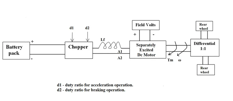
The other parameters of the electric vehicle is given below,
Motor and Controller Parameters:
Rated Armature voltage= 72 V
Rated armature current= 400 A
Ra= 0.5Ω, KΦ= 0.7 Volt second
Chopper Switching frequency= 400 Hz
The vehicle speed-torque characteristics are given by the below equation

What is EV steady state speed if duty cycle is 70%
Vehicle output voltage (V) = Battery voltage (Vb) * Duty cycle
= 72 * 0.7
= 50.4 volts.
The equation for vehicle torque is:
`Tv=Vv*(K phi )/ (Ra) - ((Kphi)^2)/ (Ra)*omega`
where,
Tv = Vehicle torque
Vv = Vehicle voltage
`Kphi =`Motor constant
`omega =` Steady state speed rad/s
Ra = Armature resistance
Substituting the given values in above equation we get,
`Tv= 50.4* (0.7/0.5)-(0.7)^2/0.5*omega`
`Tv=70.56-0.98omega`---------------------(1)`
The given equation is
`Tv=24.7+0.0051omega^2`---------------------(2)
At steady state Eq 1 = Eq 2. Therefore we get
`70.56-0.98 omega = 24.7 + 0.0051 omega^2`
`0.0051 omega^2 + 0.98 omega - 46.55 = 0`
we can slove this above equation by quadratic equation formula,
`x = (-b +- sqrt(b^2 -4ac))/(2a)`
`omega = (-0.98+- sqrt(0.98^2-4*0.0051*-46.55))/(2*0.0051)`
`omega=`38.9150 rad/s.
Steady state speed is 38.9150 rad/s
371.610877 RPM
===================================================================================================================================
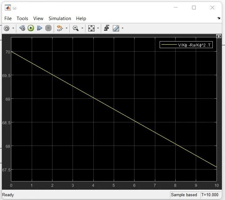
3. Develop a mathematical model of a DC Motor for the below equation using Simulink.
ω= V/Kϕ -Ra/Kϕ^2 .T
The above equation matlab model is as below:
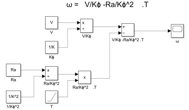
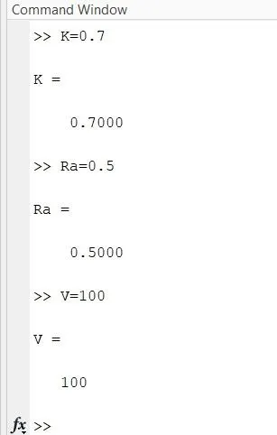
The inputs V, K, Ra are kept user defined which can be entered in command window we have taken the below values
The ramp block is used for torque input and the block parameters are kept defaults by using all above values the simulation is runned an following graph output is obtained :
===================================================================================================================================
4. Refer to the blog on below topic:
Induction Versus DC brushless motors by Wally Rippel, Tesla
Explain in brief about author’s perspective.
Wally Rippel is a long-time proponent of electric vehicles. Prior to joining Tesla Motors, he was an engineer at AeroVironment, where he helped develop the EV1 for General Motors and was featured in the documentary movie, Who Killed the Electric Car? Wally has also worked for the Jet Propulsion Laboratory on electric vehicle battery research, among other projects. In 1968, as a Caltech undergraduate student, he built an electric car (a converted 1958 Volkswagen microbus) and won the Great Transcontinental Electric Car Race against MIT.
The author started with IEC engine dominance in the vehicle feild as all engine where same only the user requirement is needed to develope a vehicle.There is no one best engine type, rather there are different types of engines to suit personal requirements, such as price and performance. This is also true for electric vehicle drives. according to it later then he divereted to HEV and EV.
Then he said about their is no one size fits , he wants to say that a single development can be carried out for years and years by giving the following example of battery developement. And futher he said about the dc brushless and induction motor usages in future.
Back when I had hair on my head and carried a slide rule, there were lead acid batteries, DC brush motors, and contactor controllers. Today, none of these remain (including my hair). Lead has been replaced by lithium and DC by either DC brushless or induction. Contactors, meanwhile, have given way to modulating inverters. So, will each of these elements also become obsolete in the near future or is it possible that some “stability” may be at hand? Without a good crystal ball, it is hard to predict the future. My guess, however, is that we will see both induction and brushless machines “duke it out” for many years to come. Each will have its loyal proponents and religious detractors.
A Closer Look
So what are these two technologies? How do they work? What differentiates them? And what do they have in common? Let’s start with DC brushless drives.
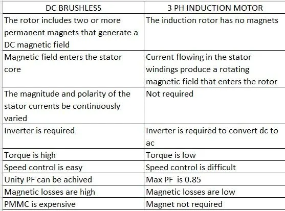
In this section the comparision of dc brushless vs induction are mentioned which is reformed in tabular format as below:
Still No Winner
My conclusion is that DC brushless drives will likely continue to dominate in the hybrid and coming plug-in hybrid markets, and that induction drives will likely maintain dominance for the high-performance pure electrics. The question is what will happen as hybrids become more electrically intensive.
At last the Conculsion is no Single winner as the dc brushless motor will be used in HEV and the induction motor in EV .If the HEV is concentrated more on electric side then the comptetion may arise.As we know change is the only constant hence no single dominance is possible in a single sector.