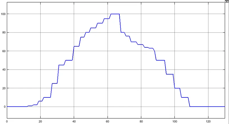
Final Project: Electric Rickshaw modelling
Que no.1
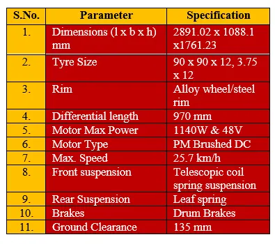
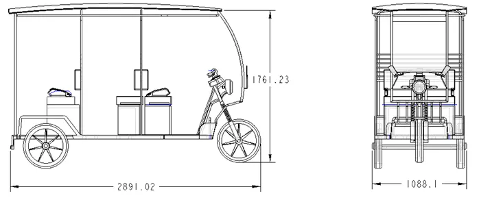
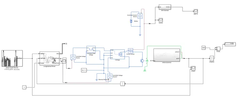
Create a detailed MATLAB model of an electric rickshaw (three wheel passenger vehicle) as per details below:
Rear wheels driven by PM brushed type motor
Assume efficiency points of motor controller and motor
Make an excel sheet of all input and assumed data
Results: For any three standard driving cycles show energy consumption, temperature rise of motor and controller for 100 km constant speed driving at 45 kmph.
AIM: Create a detailed MATLAB model of an electric rickshaw (three wheel passenger vehicle) as per details below:
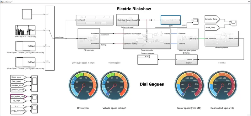
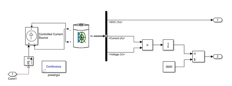
Controller satisfies lock line voltage and main circuit voltage supply vehicle, generally have a boot process of self-check, check the hole of the controller, phase line, hand, brake and so on peripheral component is normal, then enter the standby mode, hand to rotate to provide signal, pinch the brakes to cut off the hand rotating mechanical brake block signal when the wheels, the controller according to the location of motor hall element and control the opening of three phase six groups of power MOS tube.
All the function of the signal (the customer's operating instructions) by different operating switch electric car, through the wire transfer to the controller, the controller issued instructions, after internal integration chip operations controller also has the working voltage of power supply circuit provides the whole plate, because the controller and the control drive circuit, current protection circuit is also a very important part of, other chip internal procedures, can be realized according to the different application of writing different functions, the controller chip, the main work is divided into function implementation, condition monitoring, motor control, this is a summary of the driving part of the electric vehicle controller principle,Of course, there are other peripheral circuits inside the electric vehicle controller, and you can see that when you look at the circuit diagram of the 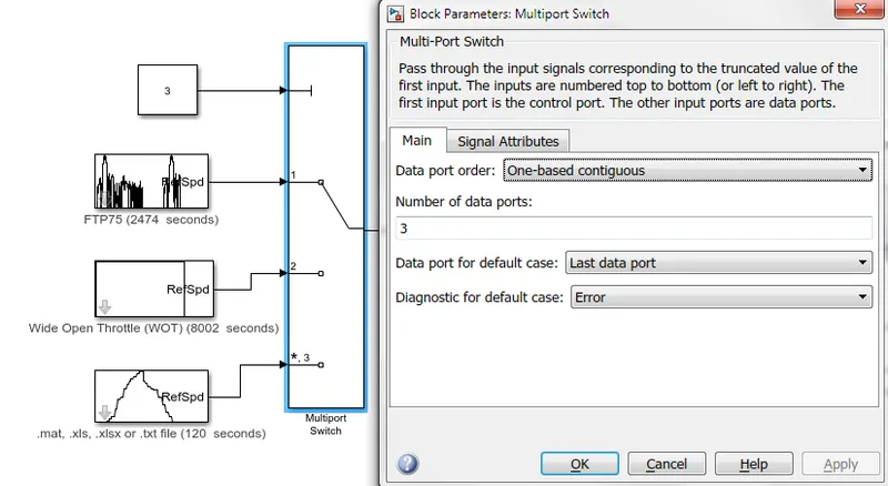
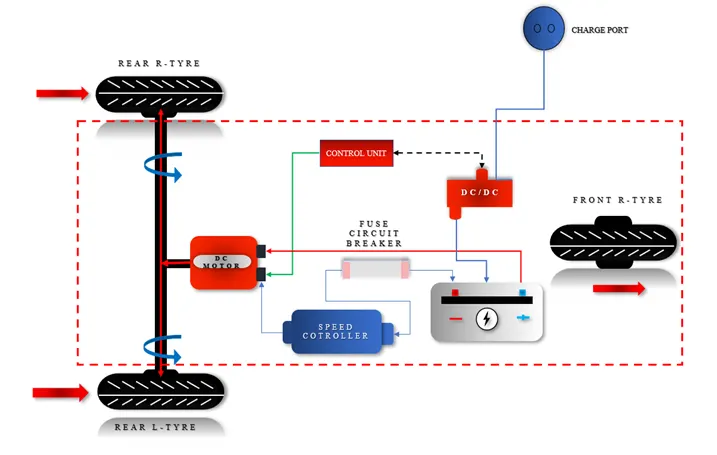
a) Battery Electric vehicle consist of an electric motor
which is powered by battery connected to it.
Electric motor is used for the movement in this type
of vehicle. It does not produce emission. In traffic,
BEV delivers high torque to the wheels and
smoother acceleration than Internal combustion
engine. It is noiseless while operating motor. But on
other side there are some disadvantages like, high
production cost, limited top speed, more recharge
time required.
b) Hybrid electric vehicle is a combination of electric
motor and new traditional Internal combustion
engine. This vehicle can work with both electric and
gasoline powered vehicle. When electric motor stop
giving power then switch into Fuel mode. In HEV
low speed mechanical electric motor used
specifically in city traffic. When vehicle use electric
power, there is no emission.
c) Range extended electric vehicle mostly designed to
run by the battery but have gasoline generator to
recharge battery when charging is low.
5. ADVANTAGES OF ELECTRIC VEHICLE (EV)
1. No fuel, No pollution.
2. It required less maintenance.
3. Total operation is noise free.
4. It generates high starting torque.
5. We can charge at home.
The main function of motor is to convert supplied electric
energy current in to mechanical energy. Brushless DC motor
(BLDC) have been much focused for many motor
manufacturers. These are more effective in term of System
cost, size, higher in efficiency, excellent controllability and
also power saving than other motor. It has only two basic
main parts Rotor and stator. The rotor is rotating part which
carry permanent magnet and stator is stationary part and
containing stator winding. The structure of stator is similar
to the induction motor. It is made up of steel lamination with
axially cut for winding.
A simple DC controller is connected between the batteries and the DC motor. If the driver floors the accelerator pedal, the controller delivers the full volts from the batteries to the motor. If the driver takes his/her foot off the accelerator, the controller delivers zero volts to the motor.
The controller takes power from the batteries and delivers it to the motor. The accelerator pedal hooks to a pair of potentiometers and these potentiometers provide the signal that tells the controller how much power it is supposed to deliver. The controller can deliver zero power when the car is stopped and full power when the driver floors the accelerator pedal, or any power level in between.
When you push on the gas pedal, a cable from the pedal connects to these two potentiometers: The signal from the potentiometers tells the controller how much power to deliver to the electric car's motor. There are two potentiometers for safety's sake. The controller reads both potentiometers and makes sure that their signals are equal. If they are not, then the controller does not operate. This arrangement guards against a situation where a potentiometer fails in the full-on position.
The very simplest DC controller would be a big on/off switch wired to the accelerator pedal. When you push the pedal, it would turn the switch on, and when you take your foot off the pedal, it would turn it off. As the driver, you would have to push and release the accelerator to pulse the motor on and off to maintain a given speed.
That sort of on/off approach would work but it would be a pain to drive, so the controller does the pulsing for us. The controller reads the setting of the accelerator pedal from the potentiometers and regulates the power accordingly. Let's say that you have the accelerator pushed halfway down. The controller reads that setting from the potentiometer and rapidly switches the power to the motor on and off so that it is on half the time and off half the time. If you have the accelerator pedal 25 percent of the way down, the controller pulses the power so it is on 25 percent of the time and off 75 percent of the time.
Most controllers pulse the power more than 15,000 times per second, in order to keep the pulsation outside the range of human hearing. The pulsed current causes the motor housing to vibrate at that frequency, so by pulsing at more than 15,000 cycles per second, the controller and motor are silent to human ears.
In an AC controller, the job is a little more complicated, but it is the same idea. The controller creates three pseudo-sine waves. It does this by taking the DC voltage from the batteries and pulsing it on and off. In an AC controller, there is the additional need to reverse the polarity of the voltage 60 times a second. Therefore, you actually need six sets of transistors in an AC controller, while you need only one set in a DC controller. In the AC controller, for each phase you need one set of transistors to pulse the voltage and another set to reverse the polarity. You replicate that three times for the three phases which is six total sets of transistors.