Final Project: Electric Rickshaw modelling
Objective:
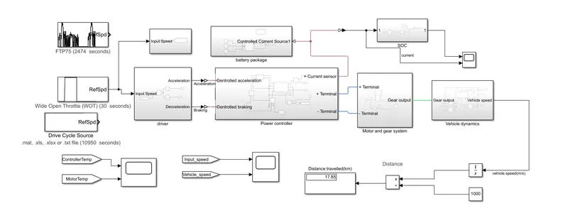
- To simulate an E Rickshaw and it has following parts they are
- Battery to provide energy
- Driver to provide whether acceleration or declaration
- Power controller to control power
- Vehicle dynamic to check all of the dynamics of the vehicle
- To check how much distance travelled display.
in Auto rickshaw, we have 3 wheelers and the ground one is the non-driving end but rear 2 he'll are driving end.
rear we had to consider PMSM motor
An excel sheet has attached of all of the assumption data we had considered
now Construction
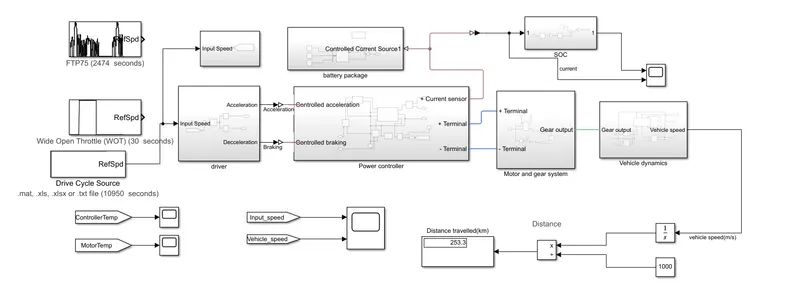
Here we had considered 3 input cycles namely
- FTP 75 which is a federal cycle
- WOT:-Wide open Throttle
- Custom cycle:-This will work according to the input we had given and output will be according to input.
Below are the subblock are given below
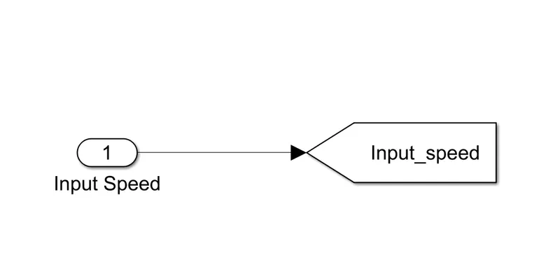
1)Input Speed:-Here the input speed can be vied and is shown below
2)Driver:-Now this is the driver and this will split the Acceleration and declaration and the block will be used as explained below
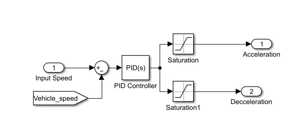
Now here the important thing is that here we are going to use a PID controller and it can be used to separate both acceleration and declaration input is given vehicle speed.
And PID controller is as shown below
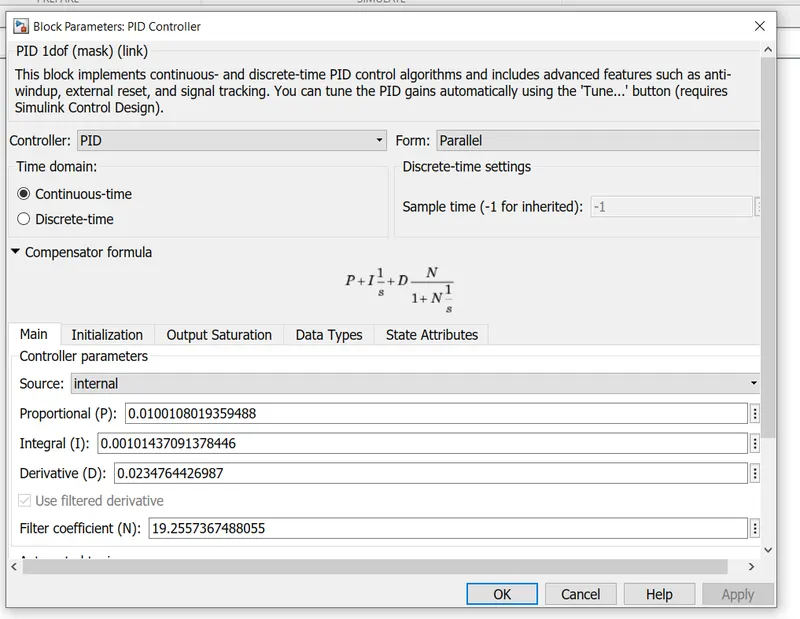
here we are going to recalculate the proportional internal and derivative values will be done by trial and error method.
3)Power Controller:-This is one of the most important parts of an electric motor.And this will give the required power required for E auto.And is explained as below
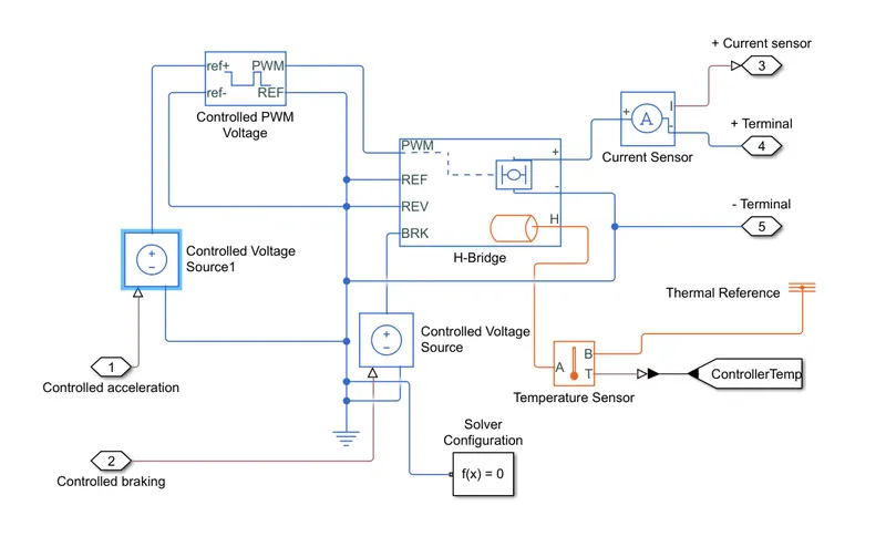
And it will get the input from previous block and it has in put both in terms of acceleration or in form of delaration.
Once it will get the signal then We are going to use Controlled Voltage Soures for both of signal.
For positive signal we had given it to the Control PMW signal and is shown below
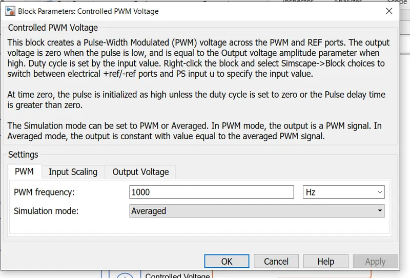
the important thing is that it has a PMW signal and this is switching frequency.
Then the positive signal will be going to the PWM signal
all negative will be given to the REF each is reference os signal
REV is the reverse of the signal and is given to the negative of all the signal
BRK is brake and declaration will be given through Controlled voltage sources
this is what input is given
And the output is given is taken from the positive and negative of the voltage.
H will show the thermal things
Positive will be given through the current sensor and output will be the same as positive current and + terminal
negative will be given at negative terminal and is terminal negative will be their
His connective to an imperative sensor and twill shown in the temperature
Twill showed the difference between the terminal od difference between B and A
here we have controlled a solver that will be used once more than 1 system that both thermal and electrical systems will be used.So to give output is used.
4)Battery Package:-This is a li-ion battery and here we are going to re calculative the required voltage and Ah required.
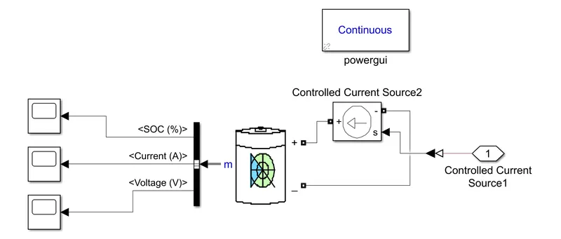
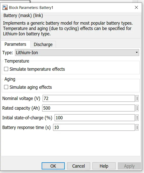
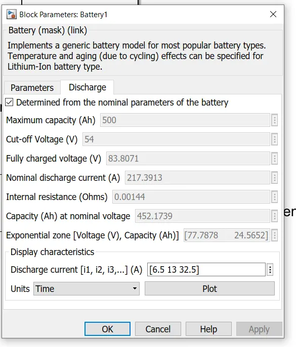
now the battery is shown above and here we are going to set the voltage and current by back-calculation and weight is considered as 250 Kg od empty od rickshaw.
and output has given to bus sector and output is soc and voltage and current can be seen.
Here output current is controlled through the current sector bus and output is there.
4)SOC estimation:-
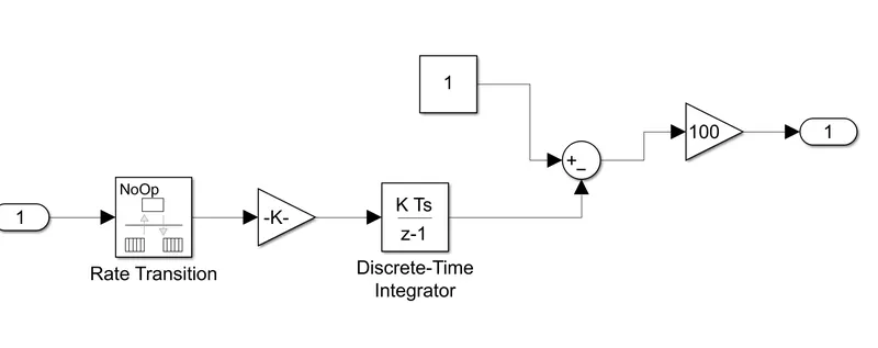
Here we are getting output in continuer time so to get discreet time then we are going to use Discreet time integrator block and output will be discreet and we are going to use some constant like 100 and all.
5)Motor and Gear System
Now moor will convert output we can get it in form of electrical energy into mechanical energy and gear can be used to get the required torque in the system.
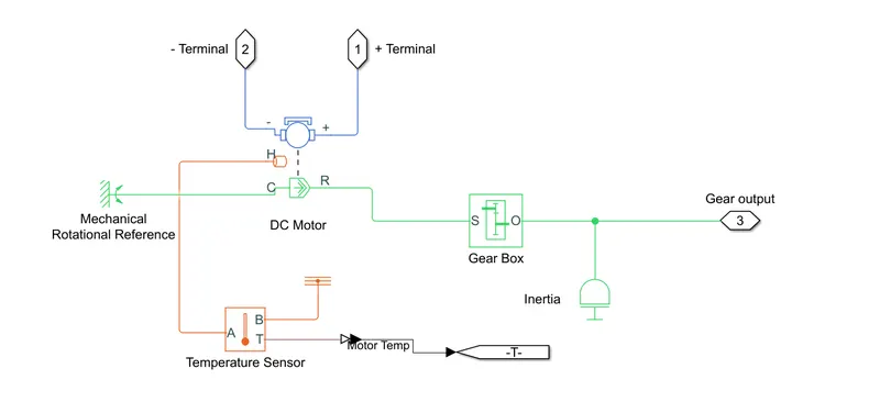
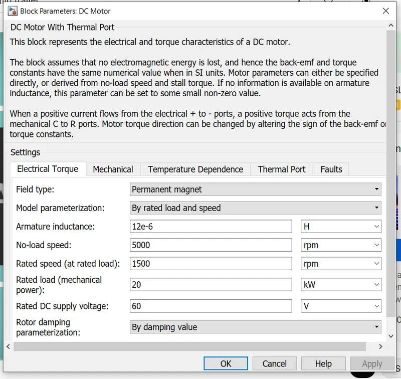
Now here we going to give two inputs by giving terminal and it has linked to the motor and the motor setting can be shown as below
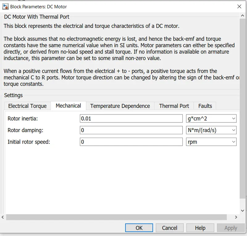
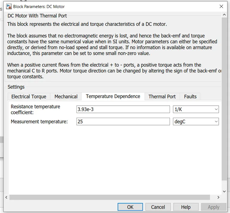
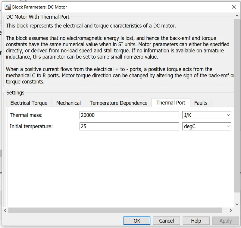
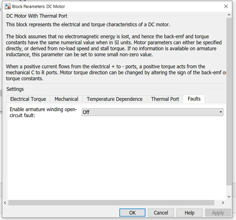
In any auto, we have 4 gear and it is a common thing in India.
Gear Output is a block that will work on to supply Torqueue and is shown below.
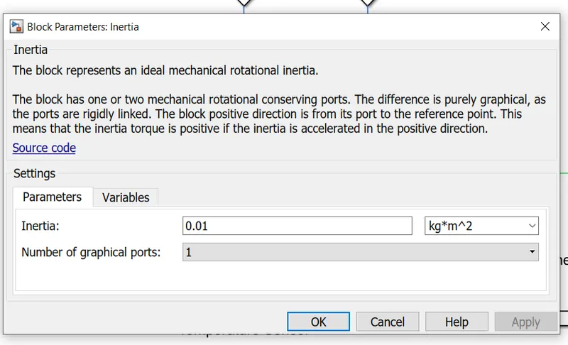
now in this block, we can have inertia and important thing is that this will tell us how much torque is required and the output of gear will work to match this.
then this output we are taking into consideration and this output could work on gear output.
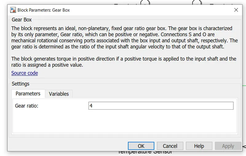
6)Vehicle Dynamics:-
This is one of the important blocks as per mechanical things are considered and the block is shown below

Now here we had considered 3 tyres and the settings in which we had given input are as shown below
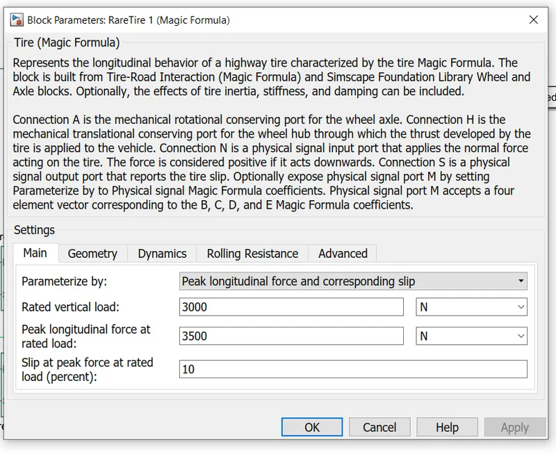
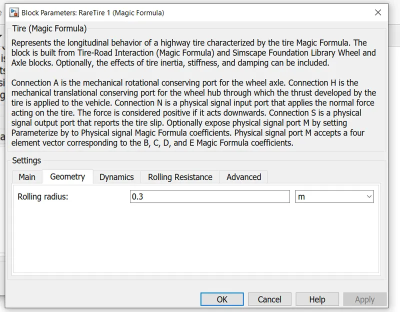
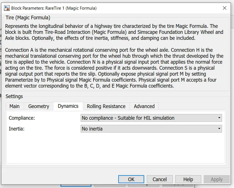
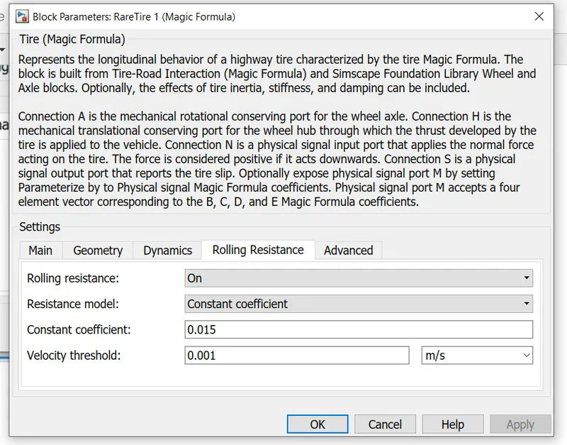
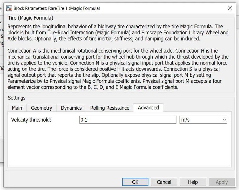
and here I had considered a hypnotical auto and it will have the above parameter. But all the 3 tyres must be the same and the important factor is that for any EV is that Vertical load and tangential load play important things. And in this particular simulation, we had considered a Velocity threshold as 0.1m/s.
And here both A were shorted and from back and we had terminated with help of ps terminator and in load.
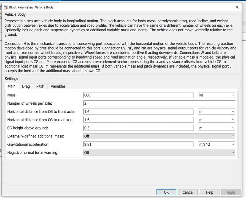
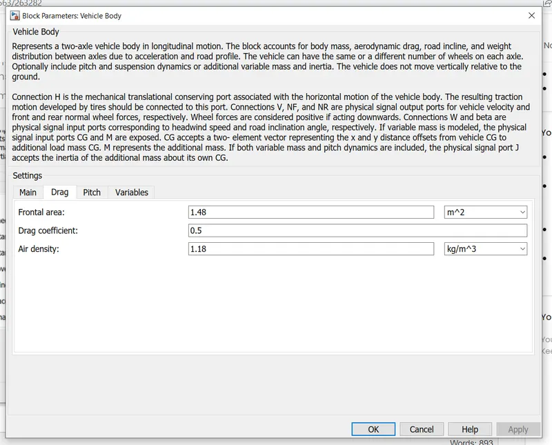
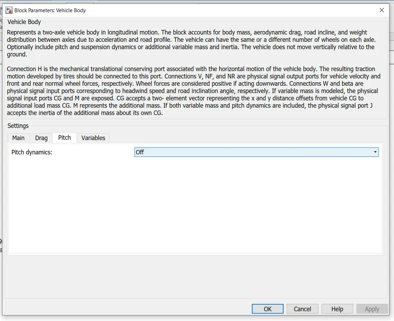
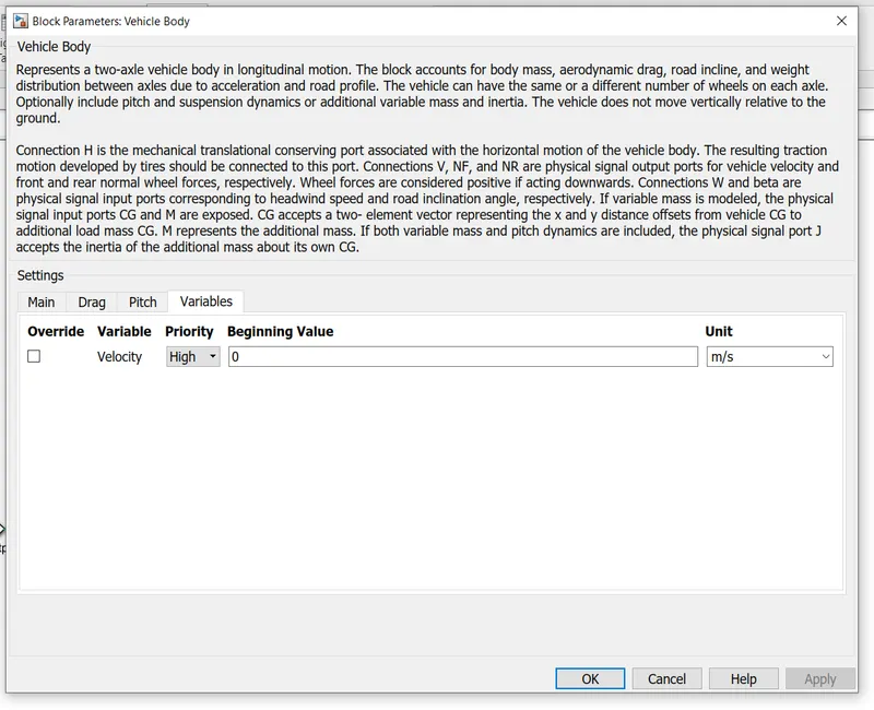
and the important thing is that mass and we had considered 600 kg and all other in rear axel is we had 2 axels and in front, we had 1 axel and other parameters were considered as shown above.
here in the above diagram that
NR will be representing reverse excel and
NF will show Forward Axel
W is constant and this constant and this in wind this will work more
Beta is an angle and terrain of work on this will be working beta on which
From this we are going to take the output will be speed and we are going to input this into it
And from above we had taken the output from the above speed and we have used an integrator and that output we have dividing I t by 3600 to get speed in kmph.
WORKING
here we had took 3 different cycles for our study
1)FTP 75
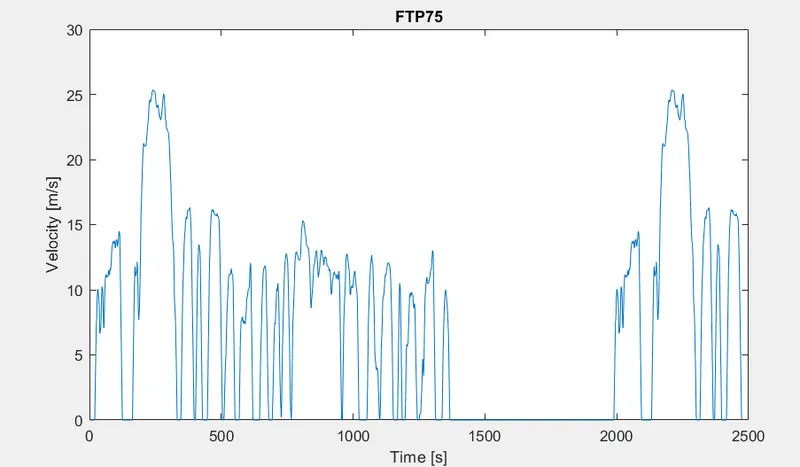
this is given by the USA and it will work efficiently for the USA
2)WOT
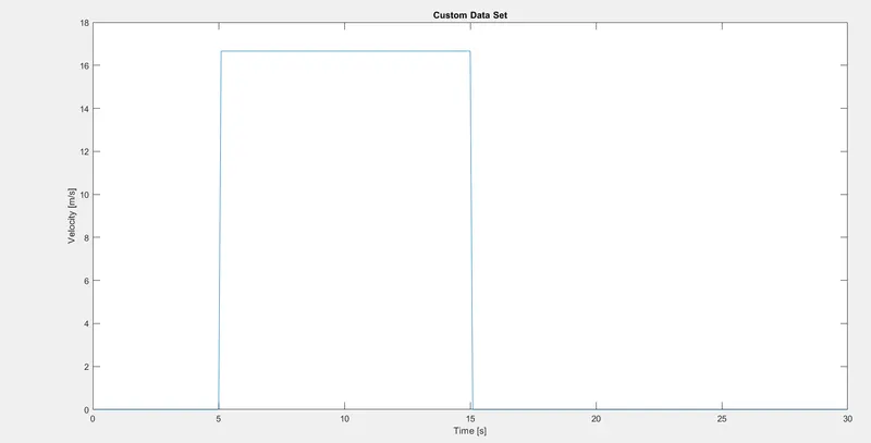
this wide-open throttle will work for a smaller time.
3)Custom drive cycle
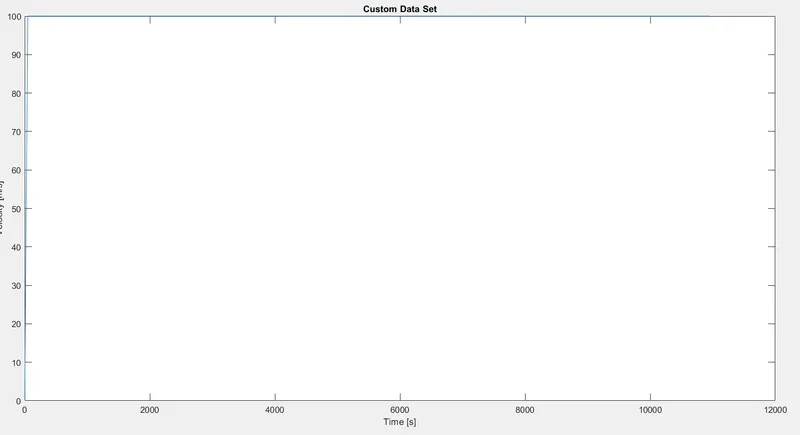
as per the given question, we are going to form a drive cycle. We had taken more time to analyse.
- Now we are going to select the input
- then we have a block called driver then it will tell whether we are going to be accurate to Decorate.
- we need to convert the data into terminal and controlled sensor
- Here the 4 blocks will provide the current to the required level we are going to estimate the SOC of the system
- we are going to see the out of current with soc
- Now terminal will be controlled into gear with help of mechanical to electrical conversion
- Gear output will be converted into vehicle speed
- Then we ate going to convert speed into the distance
- Ultimately we are going to get the distance travelled.
Result analysis
- FTP 75
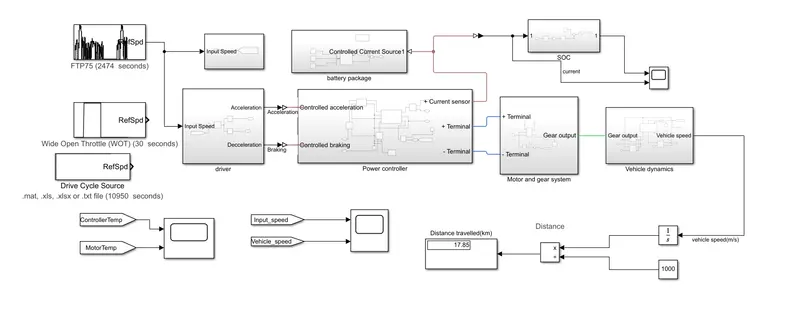
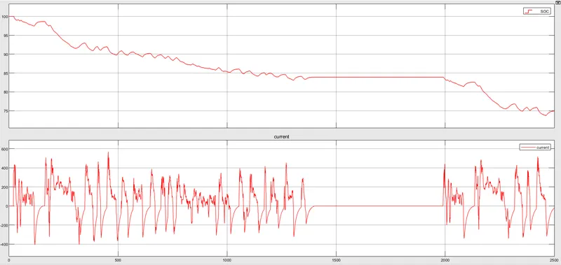
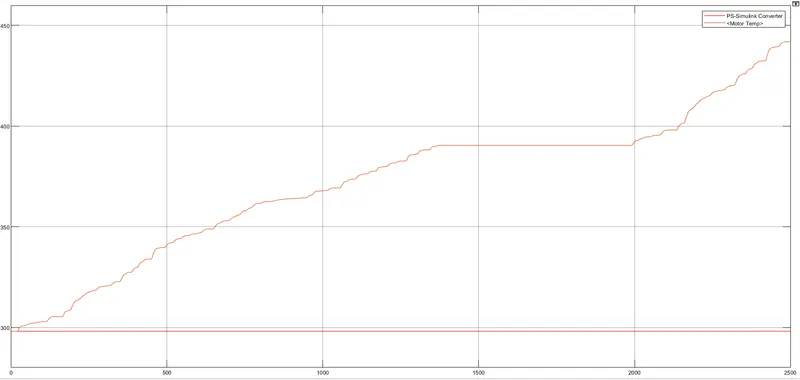
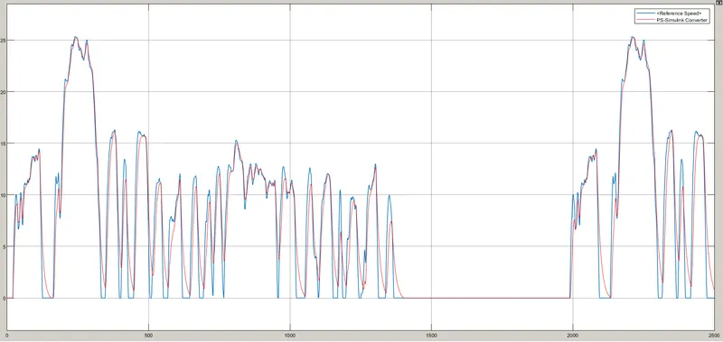
so here we can see that simulation is done for 2500 second and distance covered is 17 km
in the first graph that soc will start to decrease from 100 to 80% but current will start to fluctuate between +400 to till -400 and some part is constant and that time we can see that so acceleration will be given.
the second graph that the ps converter will increase but the motor temperature will remain constant and this is because of the heat sink which is considered in the block
this graph will show the reference speed and ps converted to speed . It is more or less the same both theoretical and practical value.
- WOT throttle
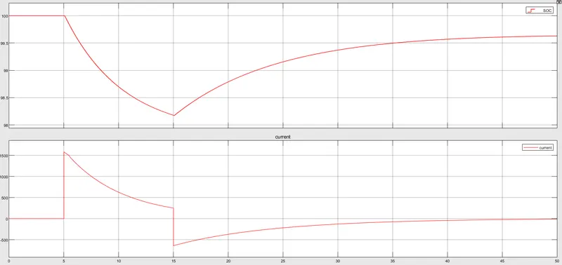
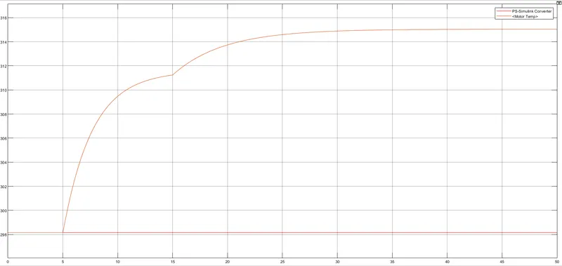
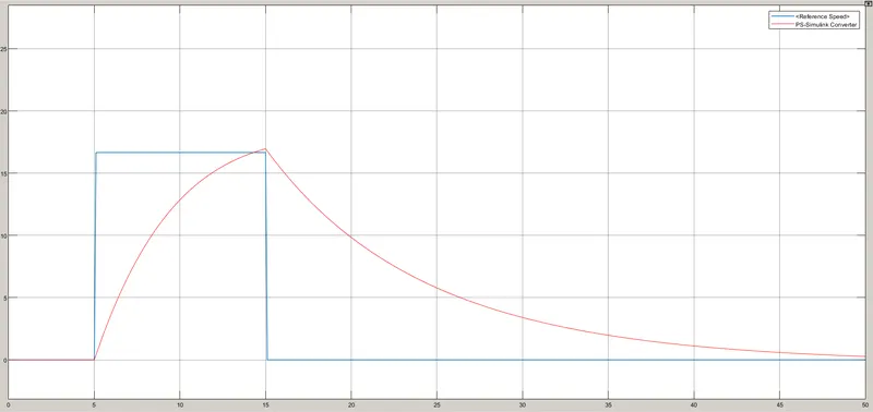
so here we can see that simulation is done for 40 seconds and the distance covered is 17 km
in the first graph that soc will start to decrease from 100 to 95% but current will start to fluctuate between +1500to till -500 and some part is constant and that time we can see that so acceleration will be given.
the second graph that the ps converter will increase but the motor temperature will remain constant and this is because of the heat sink which is considered in the block
Reference speed is the same as applied voltage but PS speed will change to the practical value.
- Custom Drive cycle
Model will be
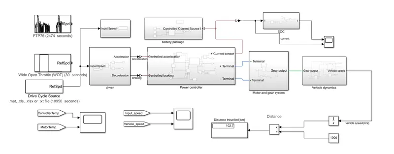
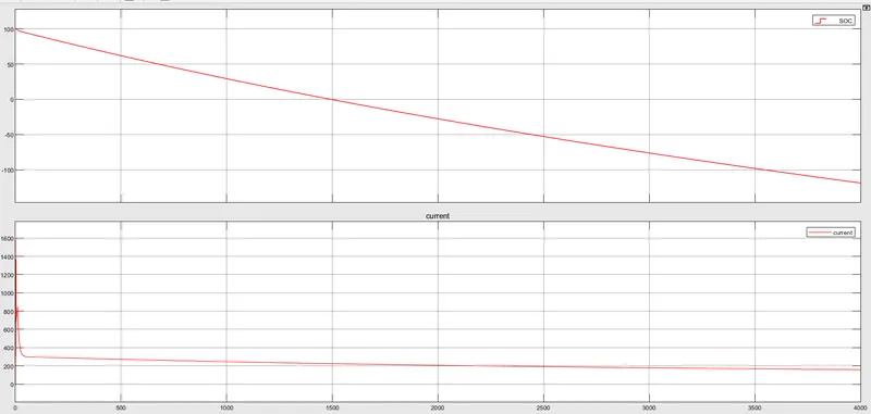
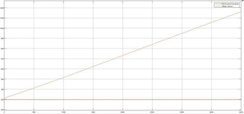
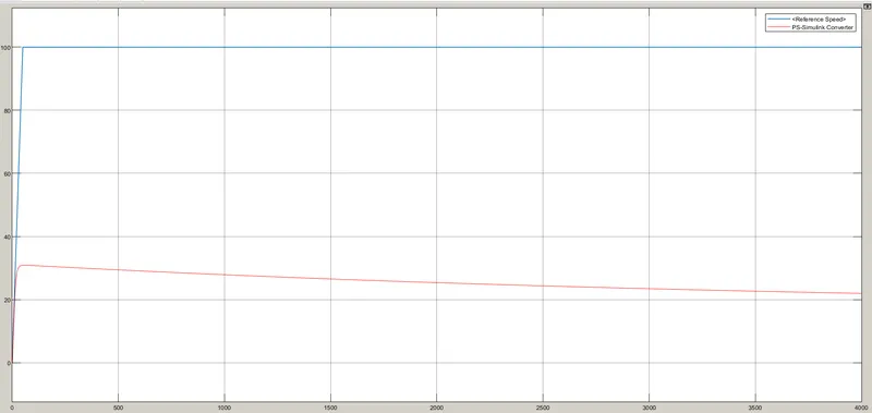
so here we can see that simulation is done for 4000 seconds and the distance covered is 104 km
in the first graph that soc will start to decrease from 100 to -100% but current will start to fluctuate between +1400to till 400 and some part is constant and that time we can see that so acceleration will be given.
the second graph that the ps converter will increase but the motor temperature will remain constant and this is because of the heat sink which is considered in the block
Reference speed is the same as applied voltage but PS speed will change to the practical value.
So the below point could be inferred those are
- Drive cycle pattern will matter more than applied time
- soc and Current will depend on the applied pattern
- practical and theoretical value can be predicted on the applied pattern.