Final Project: Electric Rickshaw modelling
Aim: Create a detailed MATLAB model of an electric rickshaw (three wheel passenger vehicle) as per details below:
- Rear wheels driven by PM brushed type motor
- Assume efficiency points of motor controller and motor
- Make an excel sheet of all input and assumed data
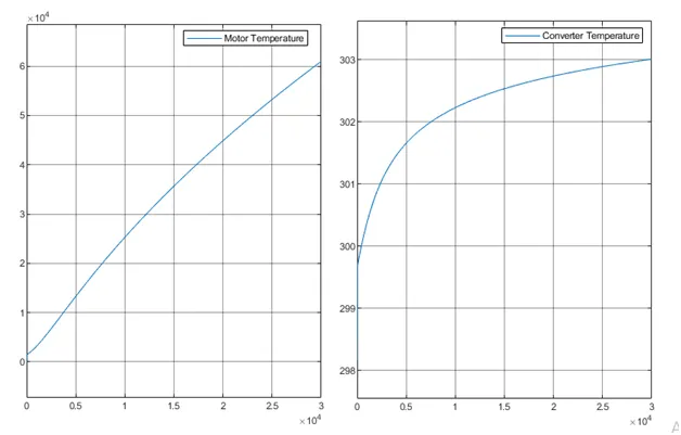
- Results: For any three standard driving cycles show energy consumption, temperature rise of motor and controller for 100 km constant speed driving at 45 kmph.
- (Note- The simulink model file should be compulsorily attached)
Solution: Electric rickshaws (also known as electric tuk-tuks or e-rickshaws or toto or e-tricycles have been becoming more popular in some cities since 2008 as an alternative to auto rickshaws and pulled rickshaws because of their low fuel cost, and less human effort compared to pulled rickshaws. They are being widely accepted as an alternative to petrol/diesel/CNG auto rickshaws. They are three-wheelers powered by an electric motor ranging from 650 to 1400 Watts. They are mostly manufactured in India and China. Battery-run rickshaws could be a low-emitter complementary transport for the low-income people, who suffer most from a lack of transport facility, if introduced in a systematic manner according to experts.
These rickshaws have a M.S (Mild Steel) tubular Chassis, consisting of three wheels with a differential mechanism at the rear wheels. The motor is brushless DC motor manufactured mostly in India and China. The electrical system used in Indian version is 48V and Bangladesh is 60V. The body design from most popular Chinese version is of very thin iron or aluminum sheets. Vehicles made in fiber are also popular because of their strength and durability, resulting in low maintenance, especially in India. Body design is varied from load carriers, passenger vehicles with no roof, to full body with windshield for drivers comfort. It consist of a controller unit. They are sold on the basis of voltage supplied and current output, also the number of mosfet (metal oxide field effect transistors) used. The battery used is mostly lead acid battery with life of 6–12 months. Deep cycle batteries designed for electric vehicles are rarely used. Weight of the electric car has also been a recurring design difficulty in them.
Block Diagram:
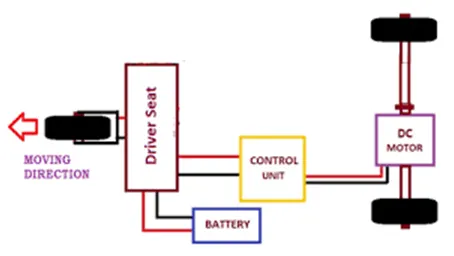
Simulation: The simulation E-rickshaw done using MATLAB simulation can be divided in three parts to explain the working:
- Drive Cycle and Controller
- Power converter and Motor (Brushed DC motor)
- Vehicle Body
Design of Vehicle body:
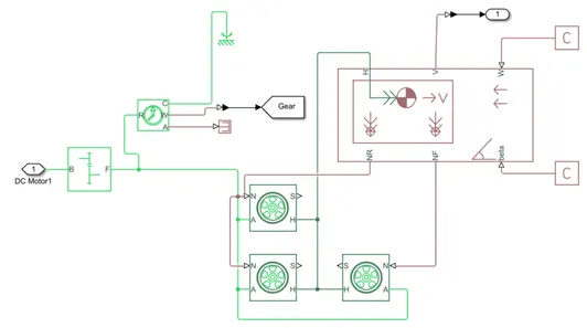
As shown in figure above a simulation model of vehicle body of e-rickshaw is designed using MATLAB simulink. The vehicle body consists of three wheels block and a vehicle body.
Vehicle body: The Vehicle Body block represents a two-axle vehicle body in longitudinal motion. The vehicle can have the same or a different number of wheels on each axle. For example, two wheels on the front axle and one wheel on the rear axle. The vehicle wheels are assumed identical in size. The vehicle can also have a center of gravity (CG) that is at or below the plane of travel.
The block accounts for body mass, aerodynamic drag, road incline, and weight distribution between axles due to acceleration and road profile. Optionally include pitch and suspension dynamics. The vehicle does not move vertically relative to the ground.
The block has an option to include an externally-defined mass and an externally-defined inertia. The mass, inertia, and center of gravity of the vehicle body can vary over the course of simulation in response to system changes.
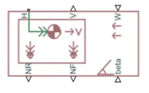
Where, V is longitudinal velocity
H is horizontal motion
NR is rear axle normal force
NF is front axle normal force
W is headwind speed
Beta is road inclined angle
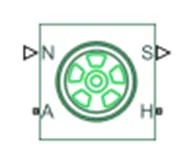
Tire or wheels: The Tire (Magic Formula) block models a tire with longitudinal behavior given by the Magic Formula, an empirical equation based on four fitting coefficients. The block can model tire dynamics under constant or variable pavement conditions. The Tire (Magic Formula) block models the tire as a rigid wheel-tire combination in contact with the road and subject to slip. When torque is applied to the wheel axle, the tire pushes on the ground (while subject to contact friction) and transfers the resulting reaction as a force back on the wheel. This action pushes the wheel forward or backward. If we include the optional tire compliance, the tire also flexibly deforms under load.
Power Converter and DC Motor
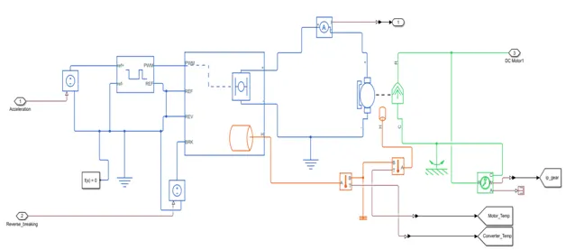
The circuit shown above provides moment to the vehicle. A power converter is connected to the DC motor and the rotating shaft of motor is further connected to gear system of the vehicle. H-bridge motor driver is a very effective method for driving motors and it finds a lot of applications in many electronic projects especially in robotics. Using H Bridge we can run DC Motor in clockwise or anticlockwise directions. This circuit is also used to produce alternating waveforms in inverters.
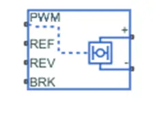
The H-Bridge block represents an H-bridge motor driver. The block has the following two Simulation mode options:
PWM — The H-Bridge block output is a controlled voltage that depends on the input signal at the PWM port. If the input signal has a value greater than the Enable threshold voltage parameter value, the H-Bridge block output is on and has a value equal to the value of the Output voltage amplitude parameter. If it has a value less than the Enable threshold voltage parameter value, the block maintains the load circuit using one of the following three Freewheeling mode options:
- Via one semiconductor switch and one freewheeling diode
- Via two freewheeling diodes
- Via two semiconductor switches and one freewheeling diode
The first and third options are sometimes referred to as synchronous operation.
The signal at the REV port determines the polarity of the output. If the value of the signal at the REV port is less than the value of the Reverse threshold voltage parameter, the output has positive polarity; otherwise, it has negative polarity.
When the thermal port is visible:
The heat generated by the bridge on-resistance and freewheeling diodes is added to the thermal port. The thermal port has an associated thermal mass and initial temperature that we can set from the Thermal Port parameters.
The bridge on-resistance and freewheeling diode resistance become functions of temperature. We can define the values for these resistances and the second measurement temperature from the Temperature Dependence parameters. Resistance is assumed to vary linearly between the two measurements temperatures. Extrapolation is used for temperatures outside of this range, except for when simulating in averaged mode with discontinuous load current characteristics.
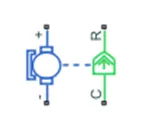
Brushed DC motors are one of the simplest types of DC motor. It uses brushes to deliver current to the motor windings through mechanical commutation. The number of coils wound around the motor and the density of the coils determine the properties of the motor. The armature or rotor is an electromagnet. The field magnet is a permanent magnet. This motor does not require any controller to operate or vary the speed.
Use the thermal port to simulate the effects of copper resistance losses that convert electrical power to heat.
Drive Cycle and Controller:
Drive Cycle
A drive cycle is typically represented by a series of data points which plots vehicle speed against time. Driving cycles are produced to assess the performance of vehicles in various ways, including fuel consumption and pollutant emissions.
Main uses of driving cycles are
- To assess the performance of a vehicle (fuel economy, emission tests)
- To analyze battery state and energy consumption in electric vehicle
- To simulate vehicle model prior to the actual development
Vehicles are designed and developed selecting components optimally. If an electric vehicle is considered, selection of motor, power electronics components, battery, and mechanical parts involves calculation and optimization to reduce the losses in terms of energy and cost.
The Drive Cycle Source block generates a standard or user-specified longitudinal drive cycle. The block output is the specified vehicle longitudinal speed, which we can use to:
Predict the engine torque and fuel consumption that a vehicle requires to achieve desired speed and acceleration for a given gear shift reference.
Produce realistic velocity and shift references for closed loop acceleration and braking commands for vehicle control and plant models.
Study, tune, and optimize vehicle control, system performance, and system robustness over multiple drive cycles.
Identify the faults within tolerances specified by standardized tests, including:
EPA dynamometer driving schedules1
Worldwide Harmonised Light Vehicle Test Procedure (WLTP) laboratory tests2
For the drive cycles, we can use:
- Drive cycles from predefined sources. By default, the block includes the FTP–75 drive cycle
- Workspace variables that define your own drive cycles.
- .mat, .xls, .xlsx, or .txt files.
- Wide open throttle (WOT) parameters, including initial and nominal reference speed, deceleration start time, and final reference speed.
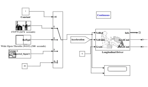
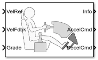
Longitudinal Driver: The Longitudinal Driver block implements a longitudinal speed-tracking controller. Based on reference and feedback velocities, the block generates normalized acceleration and braking commands that can vary from 0 through 1. We can use the block to model the dynamic response of a driver or to generate the commands necessary to track a longitudinal drive cycle.
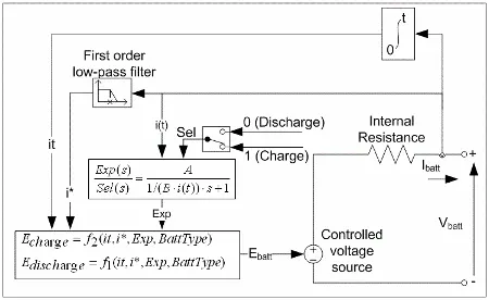
Battery System: The Battery block implements a generic dynamic model that represents most popular types of rechargeable batteries.
This figure shows the equivalent circuit that the block models.
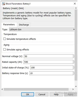
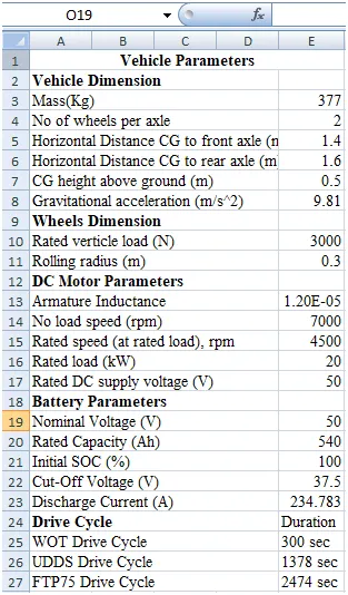
Parameters of battery taken:
Lithium ion batteries are widely used for following reasons:
Excellent autonomy: This type of battery almost doubles the autonomy of an electric vehicle.
Long lifespan: These batteries offer approximately 2000 cycles, which means they last longer than the other types.
Quick recharging: They can be 100% recharged in 1.5h hours (80% in 1 hour), and partial recharging is also possible so they're ideal when the vehicle is used 24 hours a day.
Increased load capacity: They're much lighter than the equivalent batteries that use other types of technology, so the vehicle has a greater effective capacity - a fact that can make a significant difference, especially when the vehicle is used off-road (where there are no type-approval regulations concerning weights).
Main areas of use: A wide variety of fields of use because, apart from covering the gel needs (maintenance-free), they offer certain additional features as well. If you want increased autonomy and first class performance, that's the right choice. The only limit may be their higher cost.
Winter pre-heating function: In the case of vehicles fitted with a lithium battery, the battery area has a winter pre-heating function so work can be carried out even in places with harsh sub-zero temperatures.
SOC Estimation: Tracking the state-of-charge (SOC) of each cell in a battery pack is a key role of a BMS. At every measurement step, the cells SOC estimation is updated via measuring the terminal voltage, current and temperatures. In practice, SOC can be defined as an indication of the amount of remaining charge inside the cell. A number between 0% to 100% is assigned to this indication. Precise estimation of SOC is important since:
- In contrast to gasoline tank, the batteries can be overcharged or undercharged without accurate SOC estimation.
- It lets the driver use the entire battery capacity.
- The battery pack can be used more effectively when an accurate SOC is available; thus, lighter battery packs could be used.
- The maximum available charge is given by SOC estimation. In this case, less cycles of charging are required and the life cycle is improved.
SOCs of the cells in a battery pack are utilized by the BMS to balance the state of cells. They become out of balance by time due to the small differences in their dynamics. It may happen when one cell is at high SOC limit while some other cells are in low SOC limit. In a drive cycle of HEVs, balancing of the cells state is done by boosting the cells with low SOC and bucking the cells with high SOC. The importance of accurate estimation of SOC is even more crucial in HEVs comparing to EVs since their environment characteristics are more demanding.
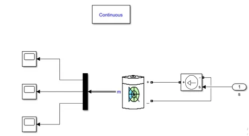
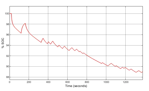
SOC of battery determined in simulation show below:
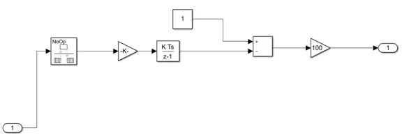
Where gain is taken as 1/(50*3600), i.e. k.u where 50 is voltage of battery taken.
Parameters:
Simulation Result:
Smulink Model:
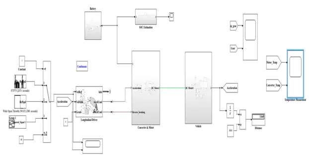
As shown in the figure different drive cycle is taken as input and at particular time the drive cycle is given as reference input to the longitudinal drive block. The input drive cycle is compared to the vehicle motion which helps in acceleration and deceleration or braking of vehicle. The output of acceleration port of longitudinal driver is given to PWM signal generator and deceleration is fed to H-bridge DC motor drive. The +ive and –ive port of converter is connected to brushed DC motor. The shaft output of DC motor is connected to gear block of vehicle. Once the gear motion is obtained the tire connected to vehicle body gets in motion depending to the drive cycle selected:
When FTP75 Drive cycle is selected:
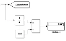
We can see that result obtained satisfies the input given to the system as a result of drive cycle is that vehicle covers a distance of 5.845km as shown below:
SOC estimation of battery for FTP75 Drive cycle
Motor and Converter Temperature for FTP75 drive cycle:
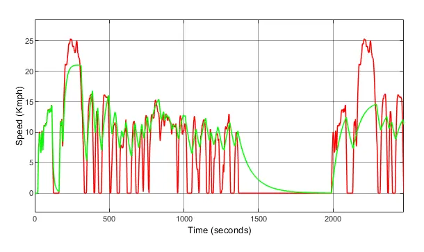
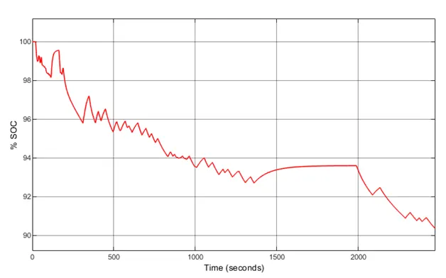
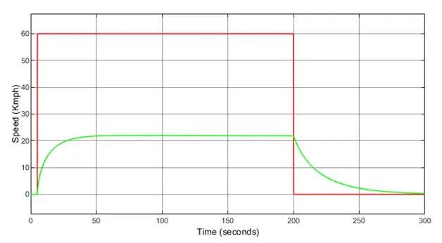
When WOT Drive cycle is selected:
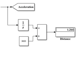
We can see that result obtained satisfies the input given to the system as a result of drive cycle is that vehicle covers a distance of 1.264km as shown below:
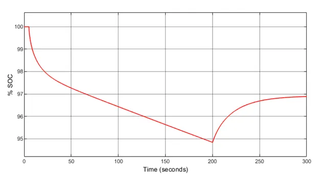
SOC estimation of battery for WOT Drive cycle
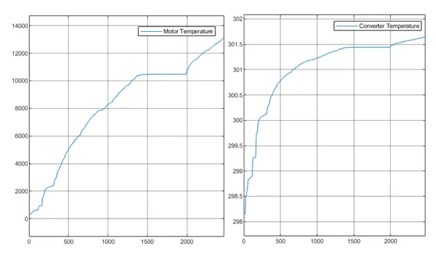
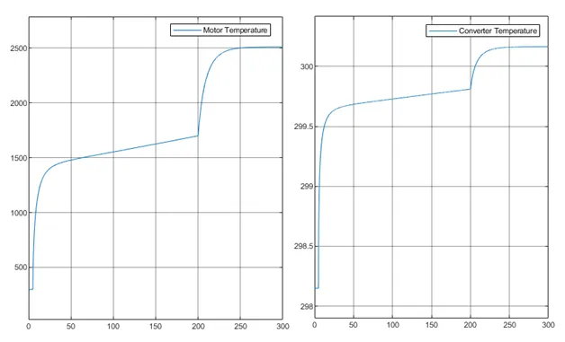
Motor and Converter Temperature for WOT drive cycle:
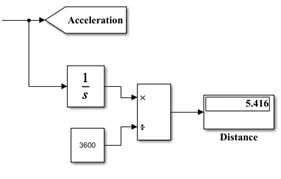
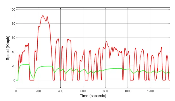
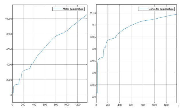
When UDDS Drive cycle is selected:
We can see that result obtained satisfies the input given to the system as a result of drive cycle is that vehicle covers a distance of 5.416km as shown below:
SOC estimation of battery for UDDS Drive cycle
Motor and Converter Temperature for UDDS drive cycle:
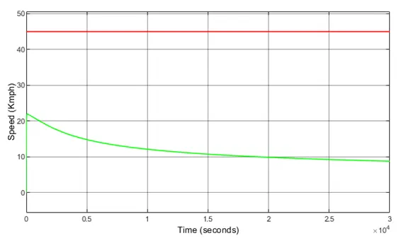
When vehicle is runs at constant speed of 45 kmph for 100km Drive cycle is selected:
We can see that result obtained satisfies the input given to the system and the result of drive cycle is shown below:
SOC of battery when vehicle is runs at constant speed of 45 kmph for 100km
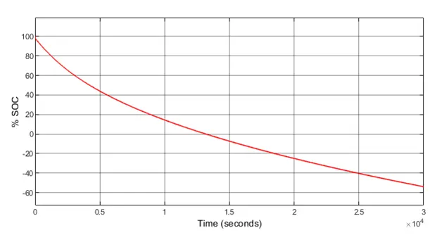
As shown in figure the SOC estimated for the battery is very poor since battery discharges completely before reaching 100 km distance and this may led harmful effect on the battery and motor. In this case the battery capacity is 540Ah. To improve this condition we can increase the battery capacity.
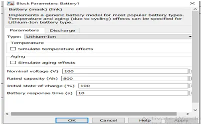
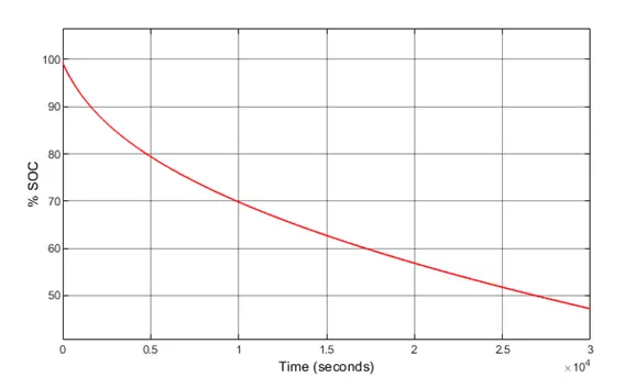
On increasing the battery capacity 800Ah and voltage to 100V the SOC of battery improves and vehicle reaches 100km before battery is discharged as in figure below.
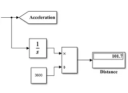
Distance Covered is 101.7km
Motor and Converter Temperature when vehicle is runs at constant speed of 45 kmph for 100km.
Conclusion: The designing of E-rickshaw is done as per given information using MATLAB 2020a. Rear wheel drive system is taken during this simulation. Different drive cycle is taken as an input to test the working of vehicle. The vehicle is also made to run at constant speed of 45kmph for 100 km and results are obtained for the following. Mahindra Treo E-rickshaw has been taken as an example for designing of vehicle body. The vehicle satisfies the parameters taken and input given to the vehicle.