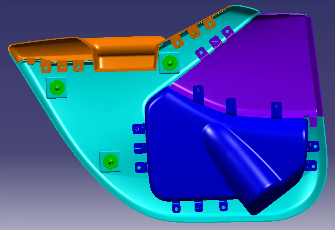
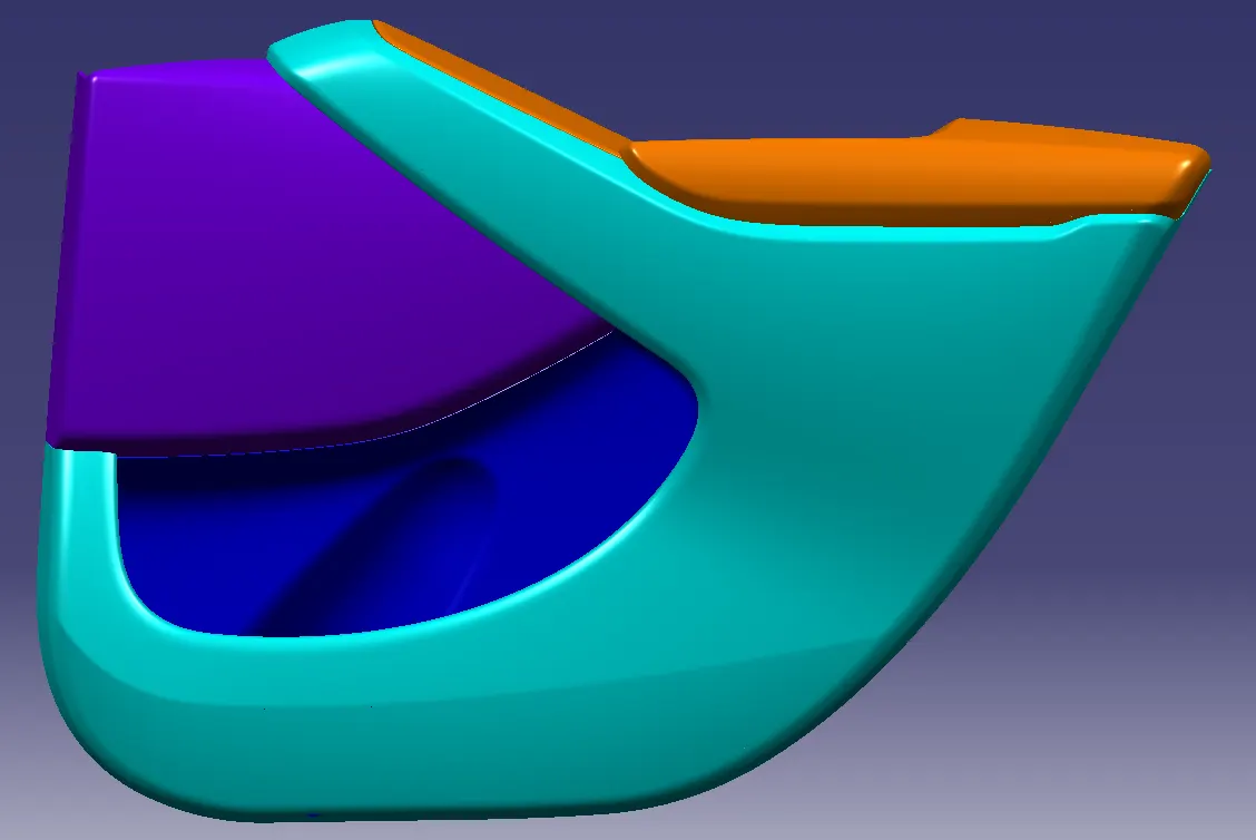
Final project : Development of a Door Trim panel
WEEK 12 FINAL PROJECT
AIM : Creation of CAD model considering following inputs as like in OEM and tier1 companies
Opened seperate part workbench for each surfaces in the given input file and worked on each surfaces induvidually.
SURFACE QUALITY INSPECTION :
Surface quality of the given class a surfaces should be checked before moving onto any working on the surface. If any patches or defects found, it should be reported to the class A stylist. those defects can be resolved only if the class A stylist agrees to do.surface quality can be checked by taking boundary of the component.
SURFACE QUALITY INSPECTION OF ARM REST :
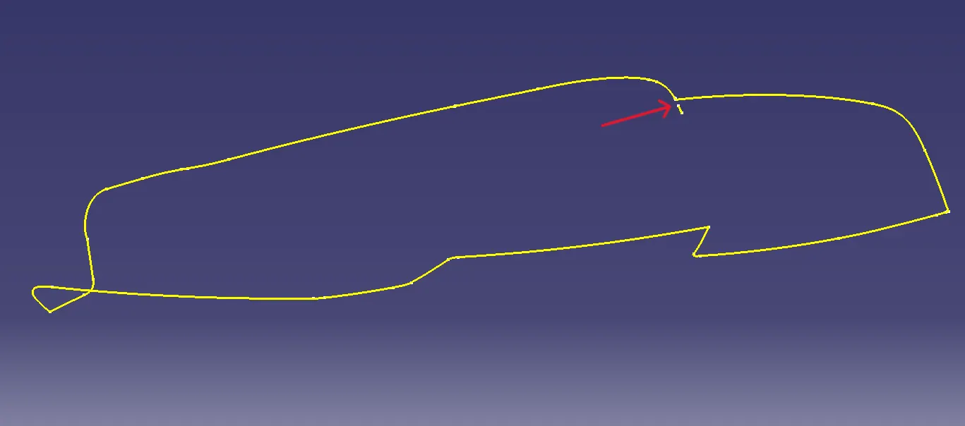
small dicontinuety in boundary is found. this due to the defect on class A surface,and it should be reported to the class a stylist.
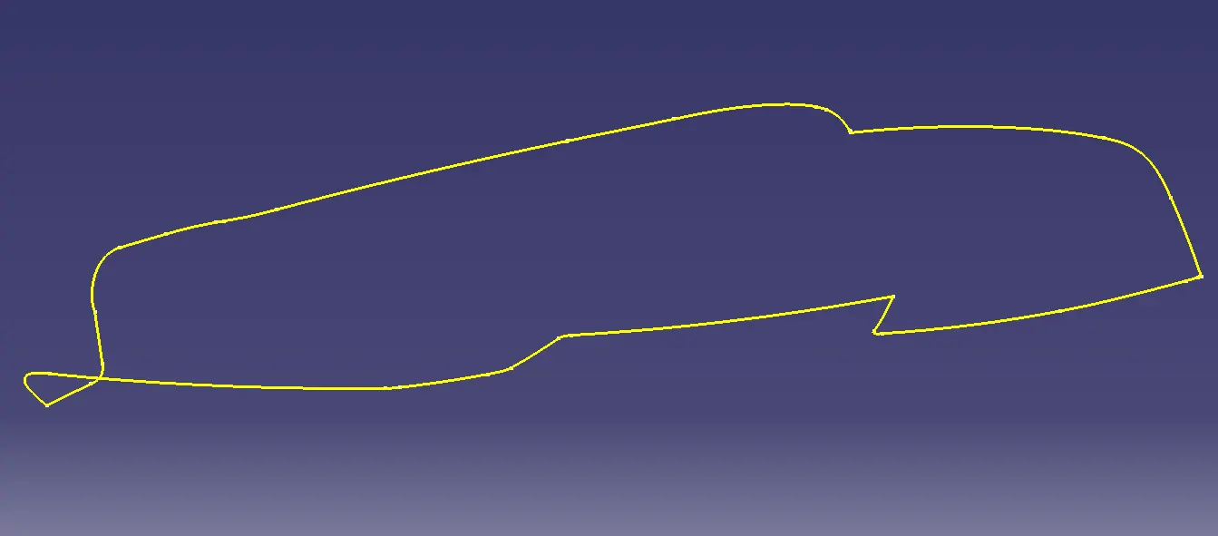
imroved class A surface:
SURFACE QUALITY INSPECTION OF MAP BOX :
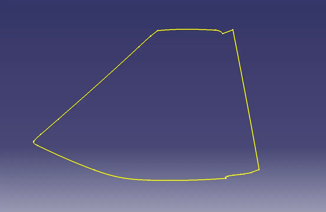
SURFACE QUALITY INSPECTION OF LOWER MAP BOX:
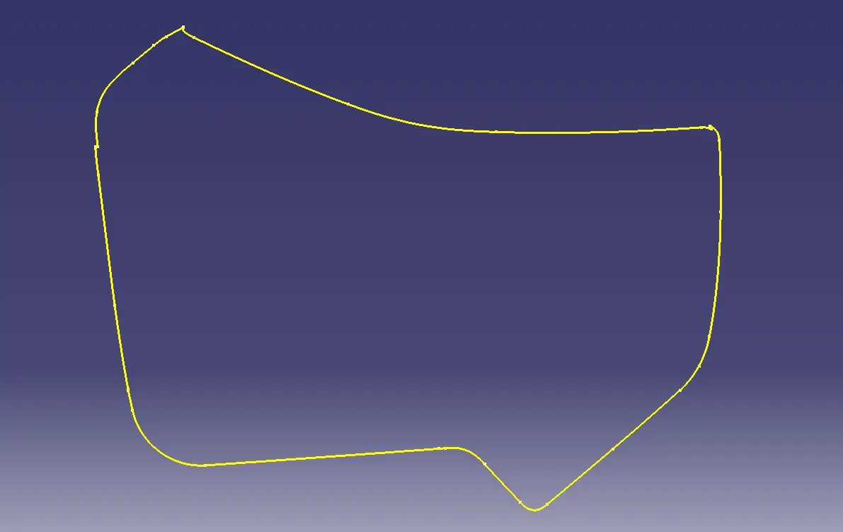
SURFACE QUALITY INSPECTION OF LOWER SUBSTRATE :
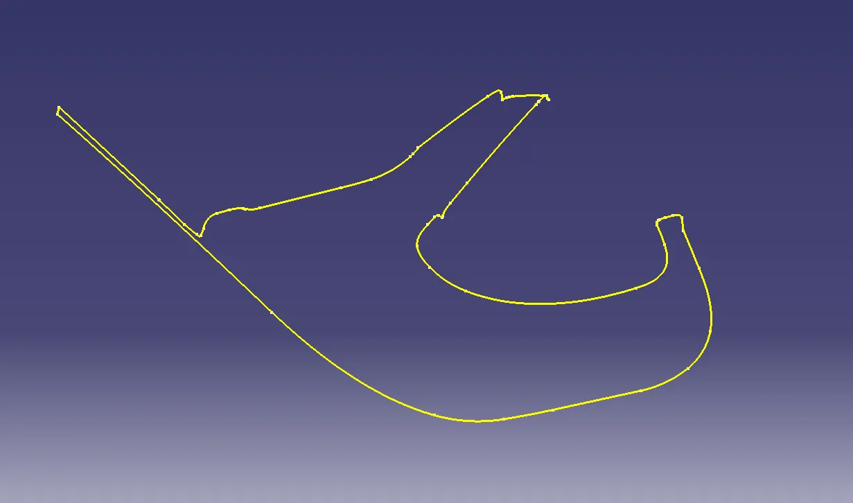
Except arm rest all other surfaces posses good surface quality. can be proceeded to surface devolopment processes
TOOLING AXIS :
It is the direction in which the moulds would travel for manufacturing of the respective component.all the necessary b side features and class c surfaces would be creating with reference to this axis of movement. Tooling axis can only be created by analysing the given class a surafce and finalises only after conducting draft analysis on the input surface respecting newly created tooling axis.placing tooling axis perpendicular to the largest flat area of the component is more convenient for manufacturing.
TOOLING AXIS CREATION OF ARM REST :
Followed bisecting method to obtain tooling axis.
- opened an axis system in the arm rest referring to the point which created on the surface
- took intersection through ZX plane.
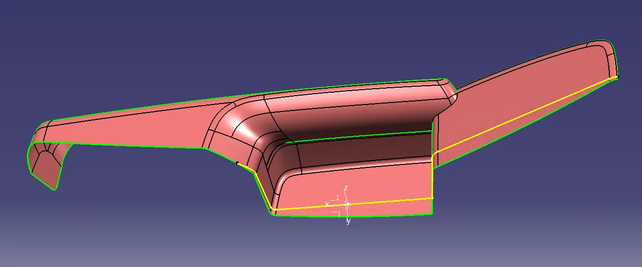
- extracted 2 slanted sides of the intersection and bisected both.
- obtained bisected line is selected as main tooiling axis
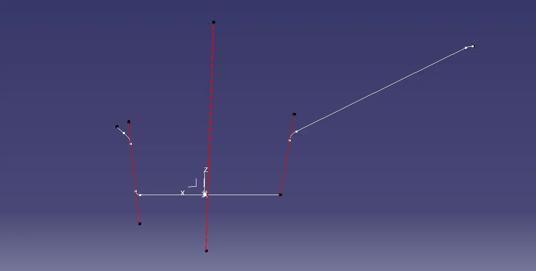
- created a point on the main tooling axis and created a line perpendicular to tooling axis through this point

- this is selected as side core tooilng axis for the lateral depression in arm rest
TOOLING AXIS CREATION OF MAP BOX :
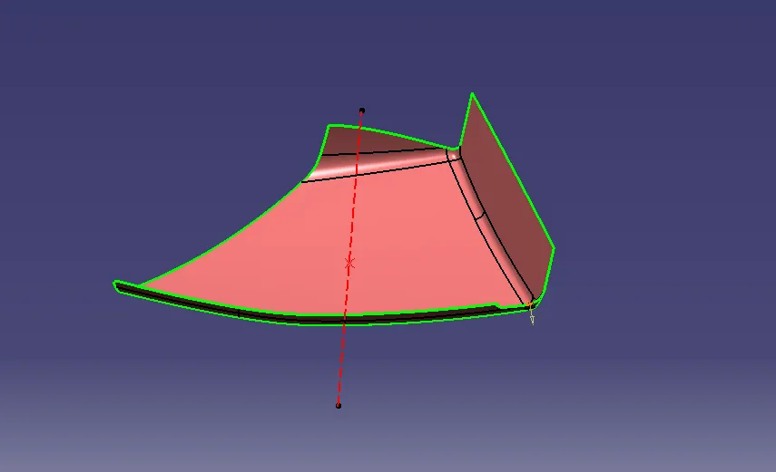
as there is no big depression on the surface, created a point on the largest flat area of the surface and created a line perpendicular to the surface through this point
TOOLING AXIS CREATION OF LOWER MAP BOX :
followed bisecting method to create tooling axis
- took intersection thorough ZX plane and extracted inclined lines
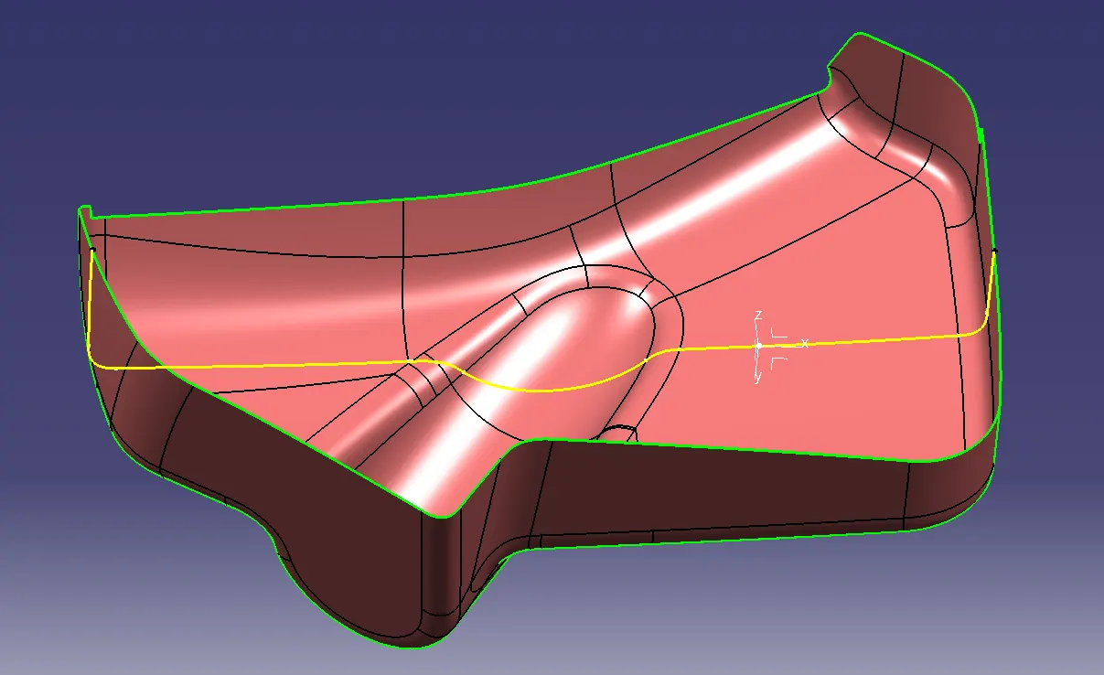
- bisected the extracted lines
- TOOLING AXIS CREATION OF LOWER SUBSTRATE :
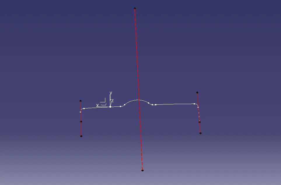
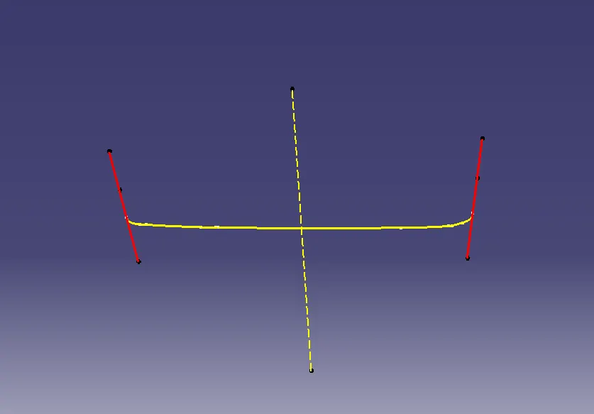
As lower substrate has side faces , have to follow bisecting method
- intersection of class A through ZX plane
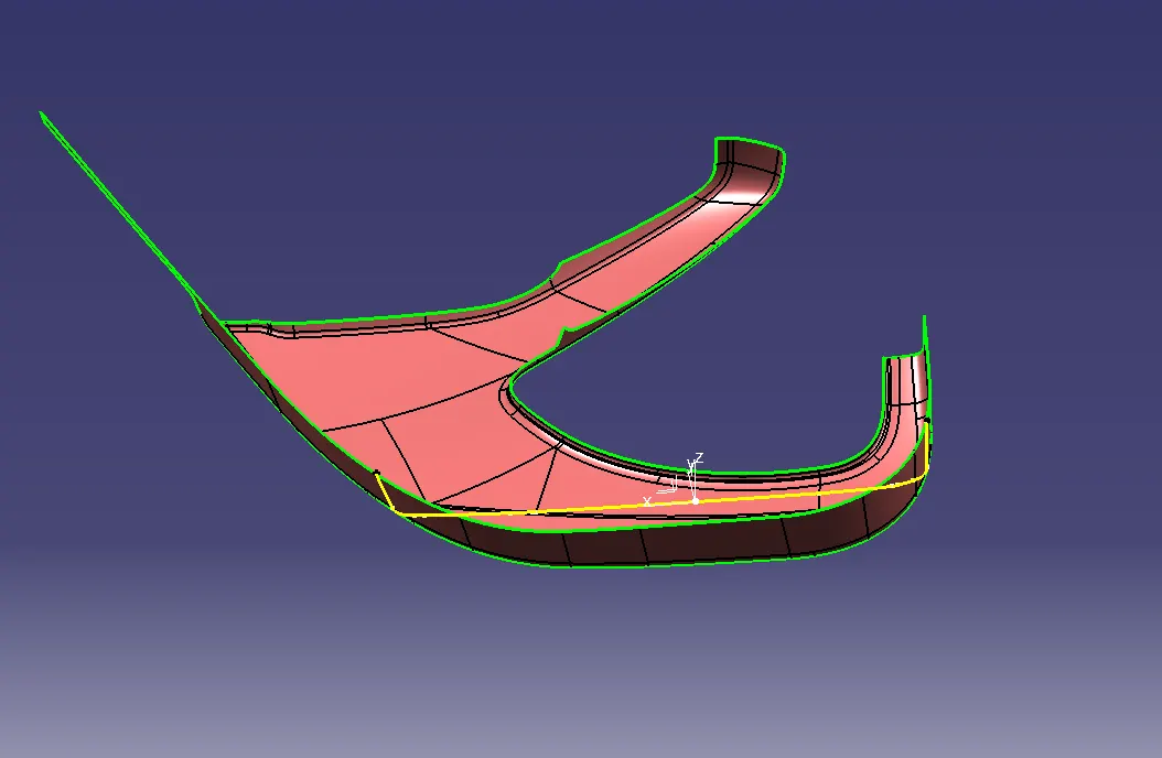
- bisected side faces
DRAFT ANALYSIS ON CLASS A SURFACES :
By performing draft analysis on the given class A surface enables to know wheather the component is easily removable or not and the tooling axis which we created is apt for manufacturing . this analysis is based on colour ranges which indicates different colours for different angles.
- go to customize view parameter and select material mode in mesh
- select feature draft analysis from analysis option by going in insert option from tool bar
- place the compass align to tooling axis with the help of compass tool
- select the surface
- click display button on the window
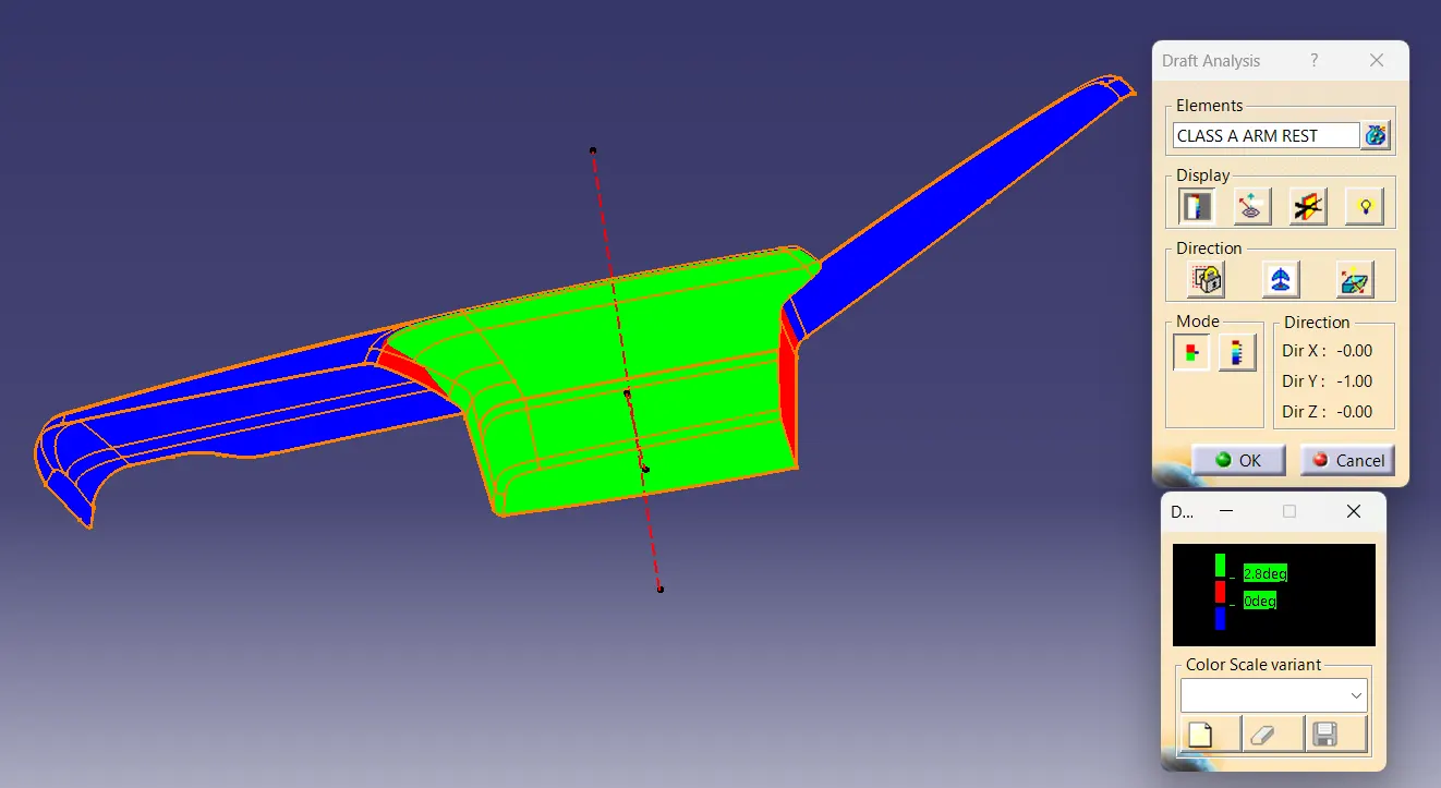
each colour zones indicates each drafting angles,green indicates within given draft angle , red indicates zero and blue indicates negative angle
DRAFT ANALYSIS ON ARM REST :
Respecting main tooling axis :
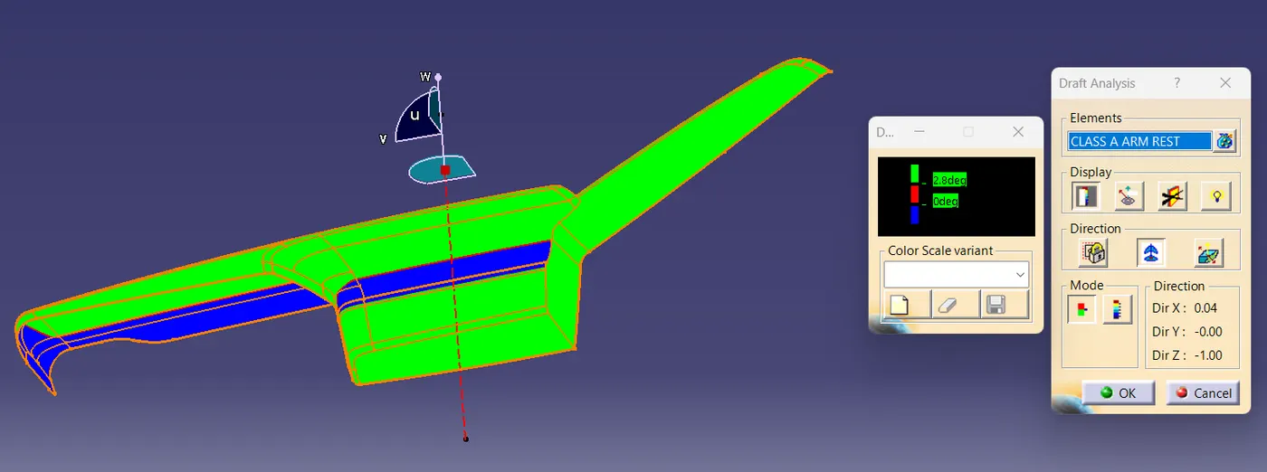
blue colour on this draft analysis indicates the regions which has negative draft angle,which is because of the design of class A. these regions cannot be cleared on main tooilng axis.this issue should be reported to the higher authority and if they grants we can proceed with this axis as main tooling axis
respecting side core tooling axis :
DRAFT ANALYSIS ON MAP BOX :
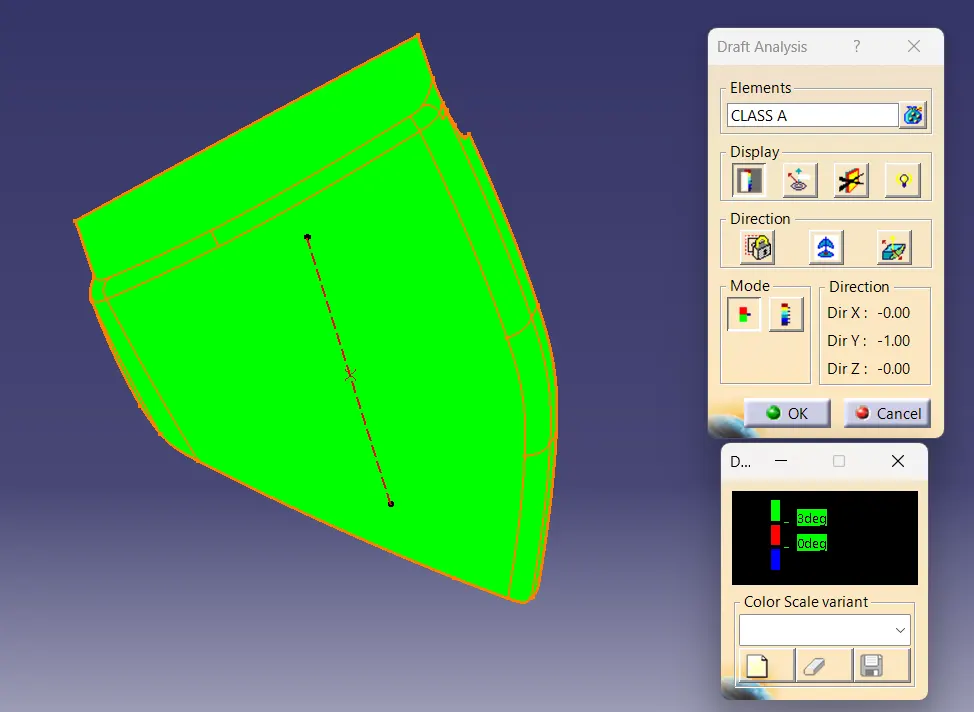
surface clears within nominal draft angle , this axis can be finalised to be main tooling axis
DRAFT ANALYSIS ON LOWER MAP BOX :
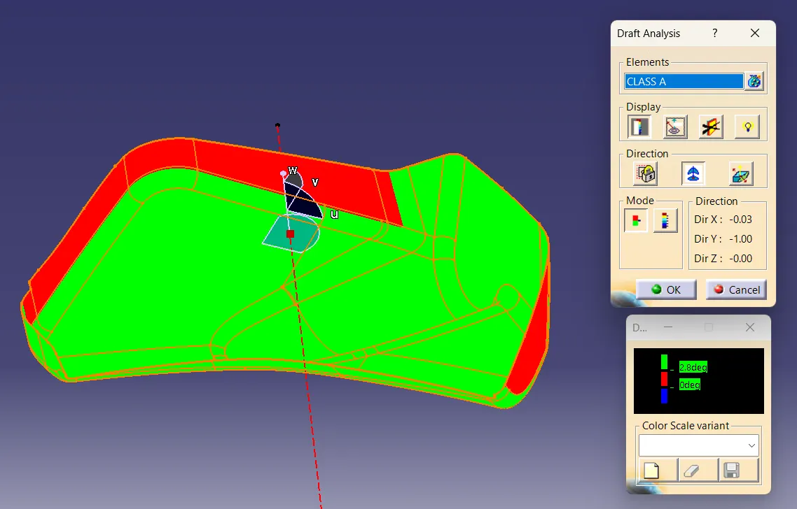
the red zones indicates 0 degree inclination with tooling axis.this can only be resolved by redesigning class A surface.report this issue to the class a stylist and if gets sanctioned , can go with this tooling axis
DRAFT ANALYSIS ON LOWER SUBSTRATE :
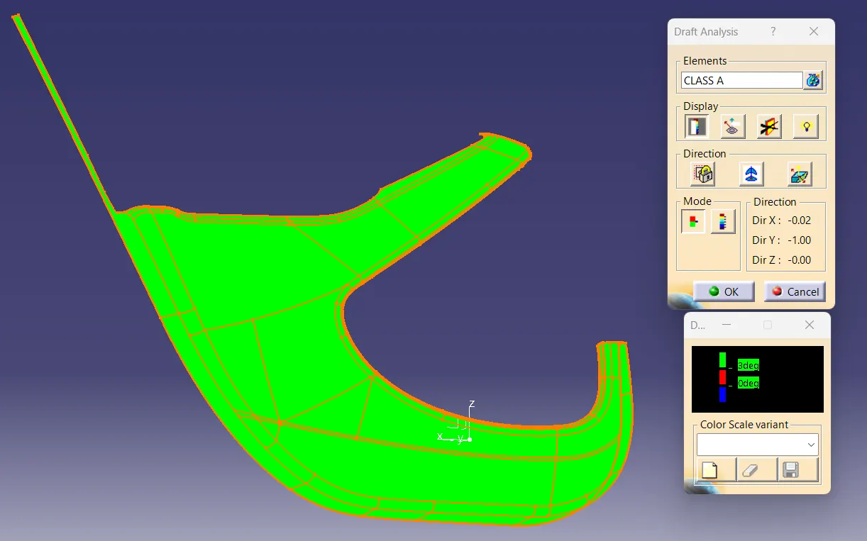
surface completely clears within the draft angle. axis is finalised to be the main tooling axis
CREATION OF CLASS B SURFACE :
class B surface is the inner face of the final moulded component or the hided face of the part . all the attachment features including ribs and parting lines comes in this face.start with creating seperate geometrical set for class b, take an offset of the given class surface to a value of 2.5mm which is obtained from given master section. some patches would be there in the offsetted plane,most of the times,fillets are the cause of patches.
CLASS B SURFACE CREATION OF ARM REST :
took an inward offset from class a surface to value of 2.5 mm as reffered in mastersections.
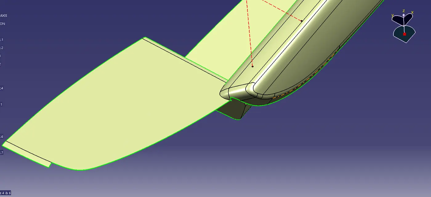
end fillet is missing in this offsetted surface
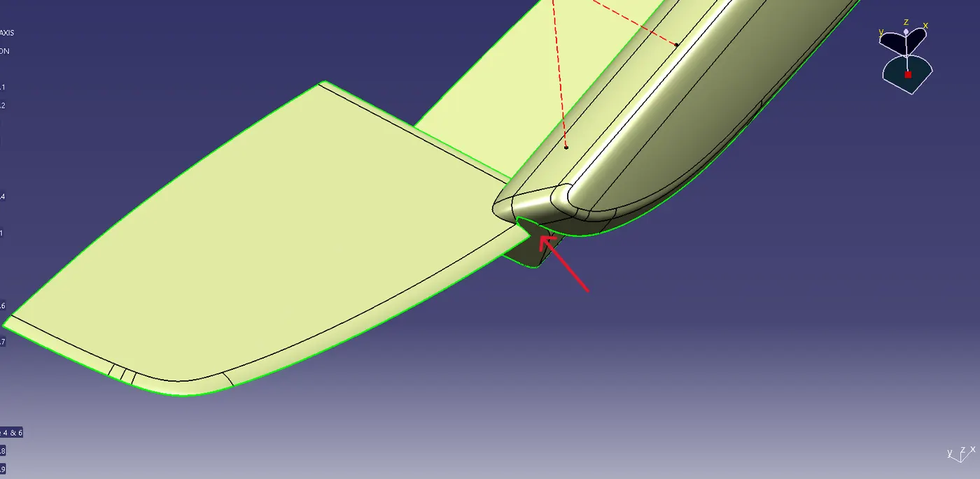
missing fillet is resolved using sweep command , but still some patches remaining
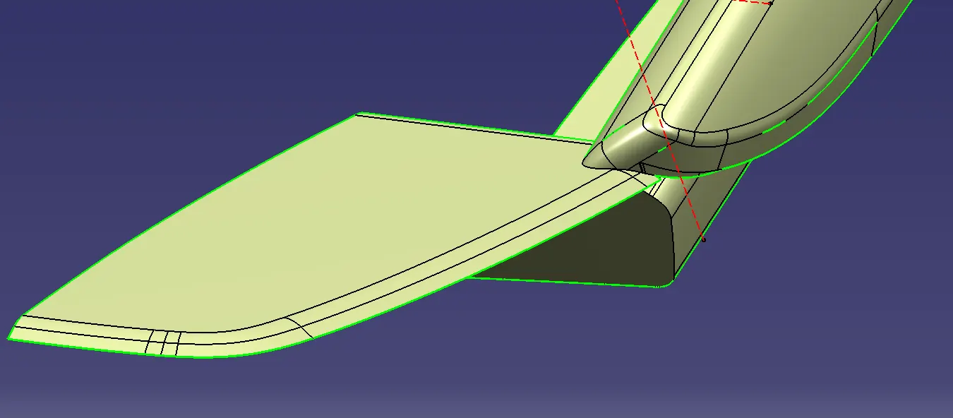
using extract, extrapolate and trimming commands remaining patches were resolved.thus CLASS B surface is obtained
CLASS B SURFACE CREATION OF MAP BOX :
took an offset from class a surface
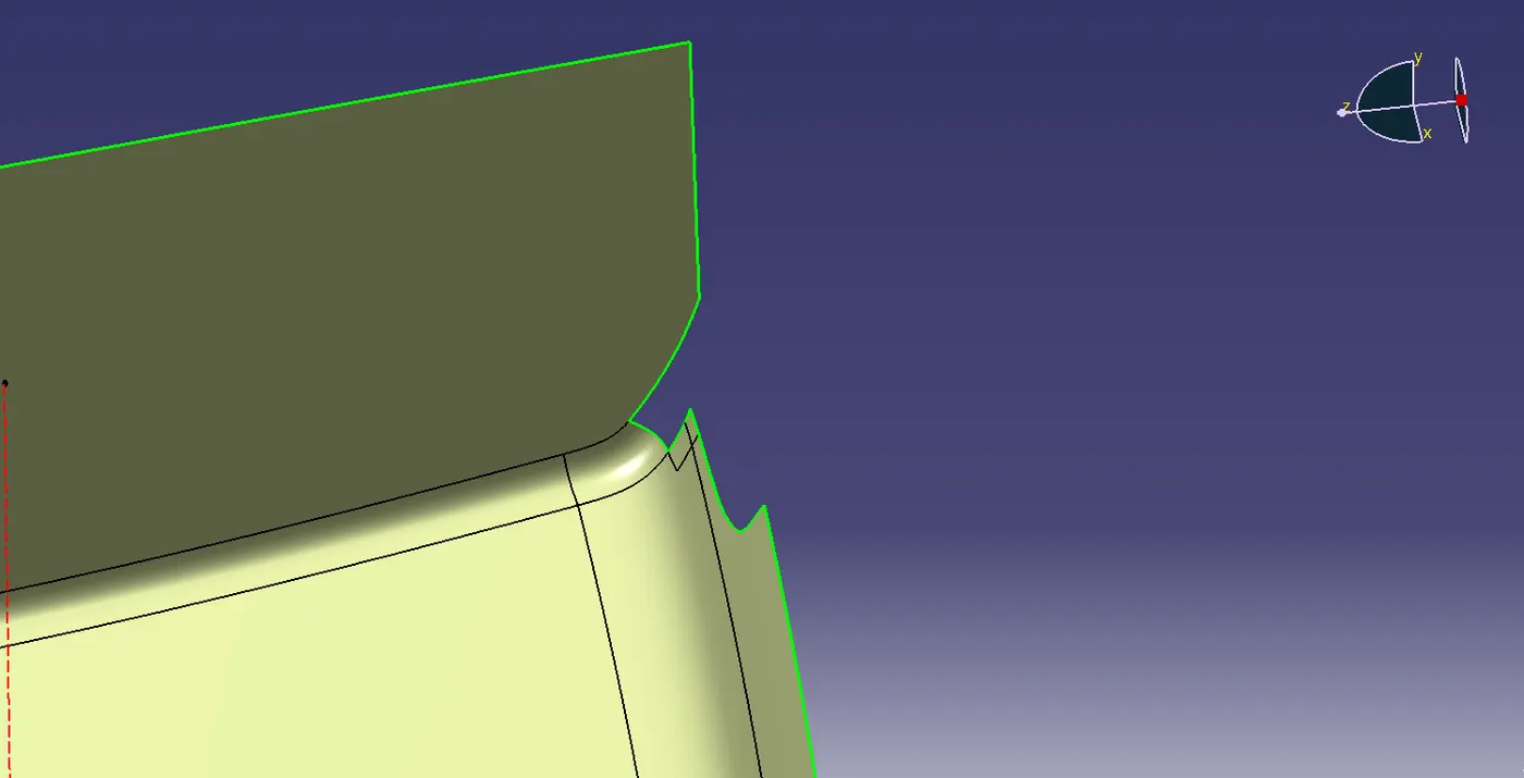
a patch occured at fillet when offsetting
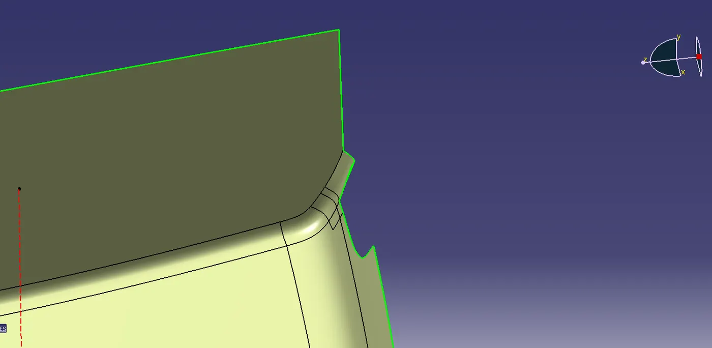
resolved the patch and CLASS B surface is obtained
CLASS B SURFACE CREATION OF LOWER MAP BOX :
Took offset of class a surface
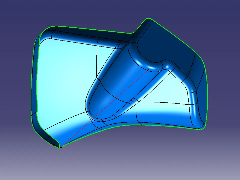
No missing parts or patches occured on offsetting thus obtained a clean CLASS B surface
CLASS B SURFACE CREATION OF LOWER SUBSTRATE :
Offsetted class A to a value of 2.5 mm
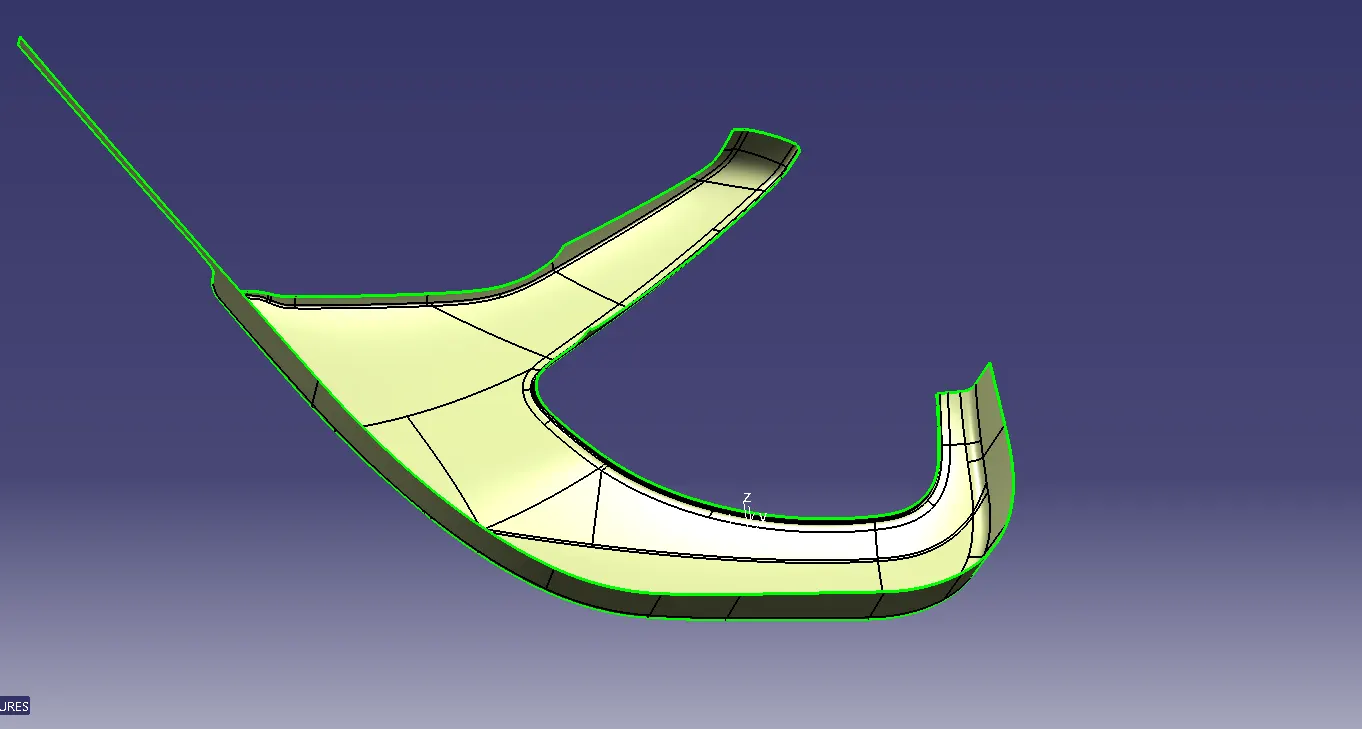
a clean CLASS B obtained without any patches or missing parts
CREATION OF CLASS C SURFACE :
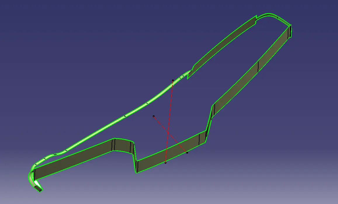
Class C is the surface which connects class A and class B surfaces. an inclination of 3 degree angle would be given to class c as drafting angle for easy releasing of solid component from mould. this slope defines the parting line on the component. for creating class c surface, sweep command is used. if the surface is parallel to tooling axis then, no drafting is needed. normal to surface option in drafting command is opted. if the surface is perpendicular to tooling axis then, drafting is needed and with drafting option from sweep command is opted . always give a second limit of 1 mm while sweeping, this helps to trim between class c and class a smoothly
CREATION OF CLASS C SURFACE OF ARM REST :
- create boundaries at edges of class a
- select sweep with draft direction from sweep option.
- select the created boundary as guide curve and tooling axis as draft direction,with 3 degree angle projecting out from class a
- follow above sweep procedure for planes which are perpendicular to tooling axis
- for planes parallel to axis,sweep in 90 degree refence to the class a surface
- extrapolate the ends of swept planes and trim altogether to get the c surface
CLASS C :
CREATION OF CLASS C SURFACE OF MAP BOX :
followed the same procedures used for class c creation of arm rest
CLASS C :
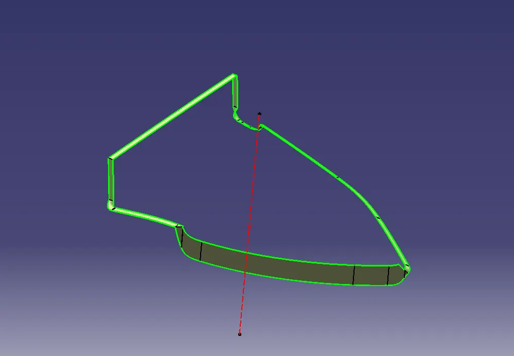
CREATION OF CLASS C SURFACE OF LOWER MAP BOX :
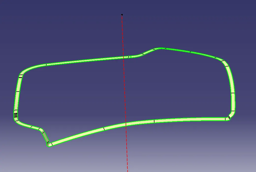
CREATION OF CLASS C SURFACE OF LOWER SUBSTRATE :
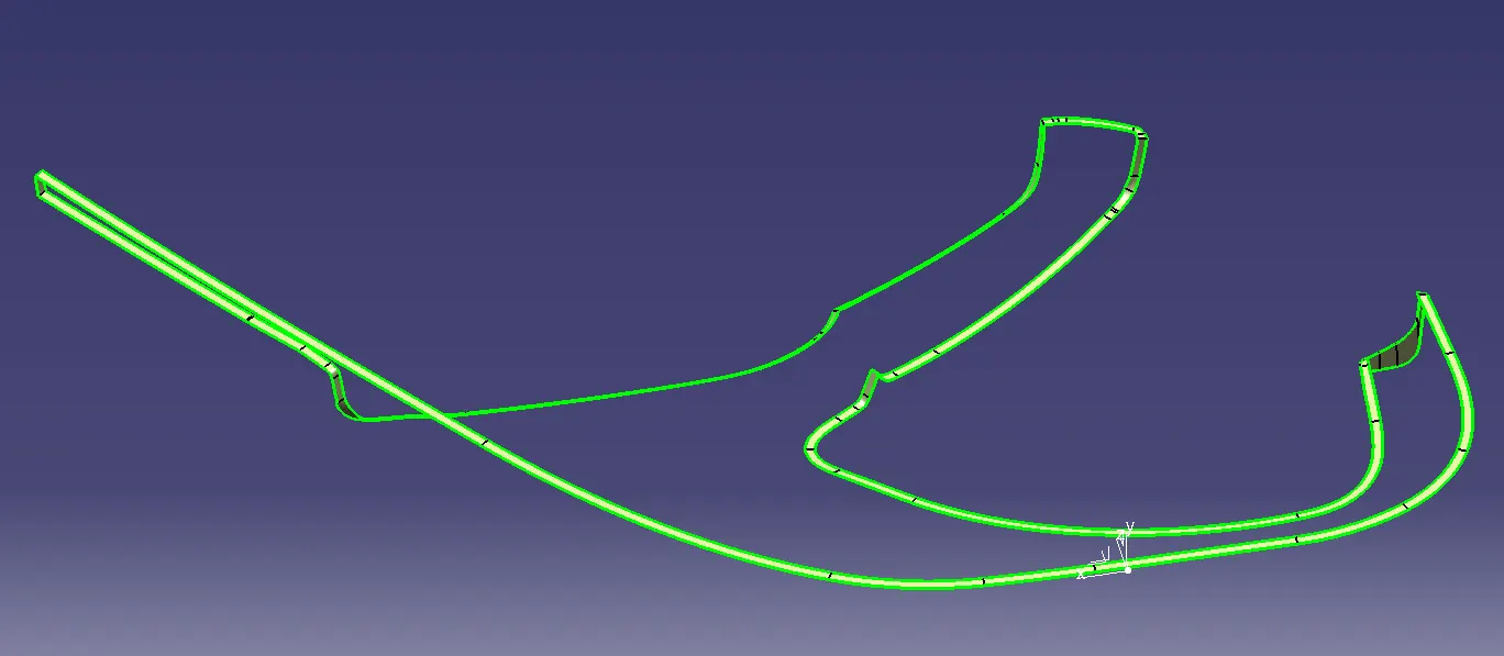
CLASS A&C :
created class c surface is trimmed with class a surface.
CLASS A&C OF ARM REST :
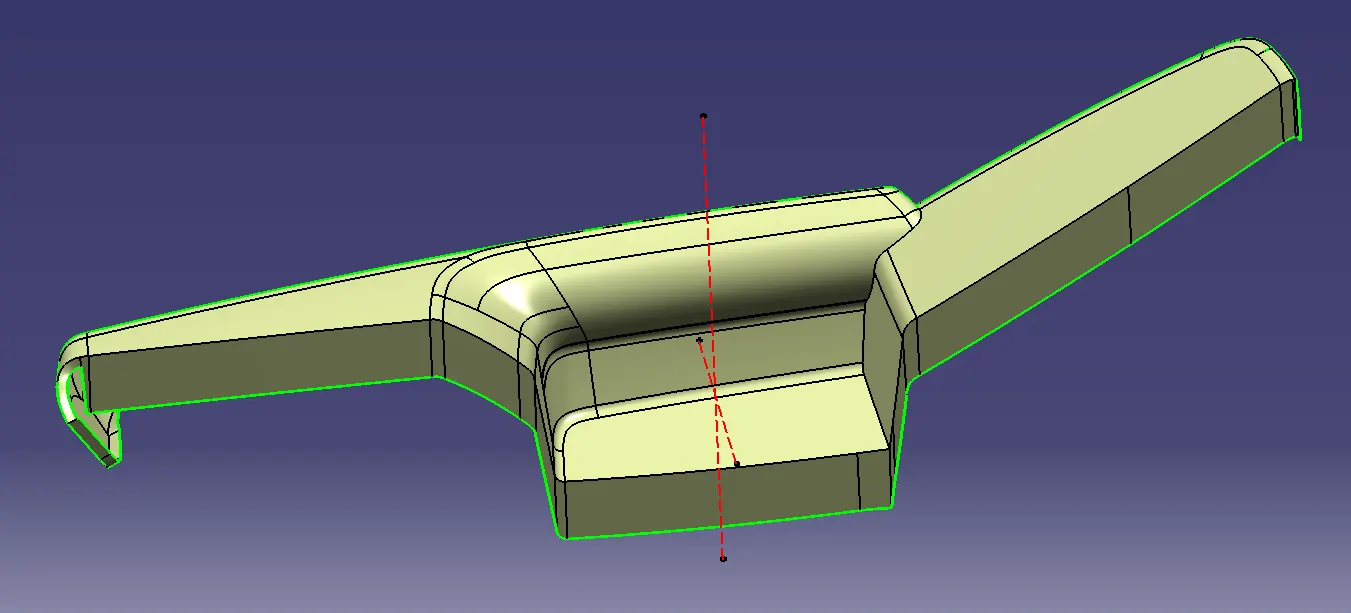
CLASS A&C OF MAP BOX :
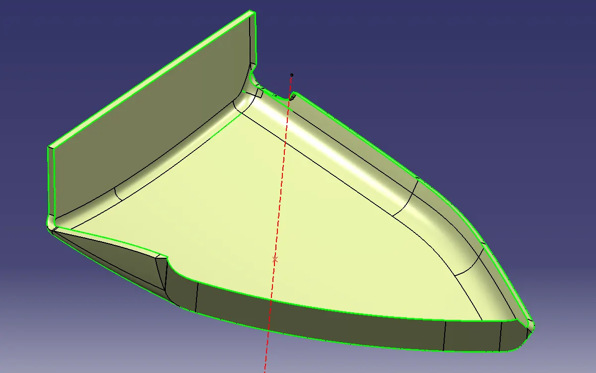
CLASS A&C OF LOWER MAP BOX :
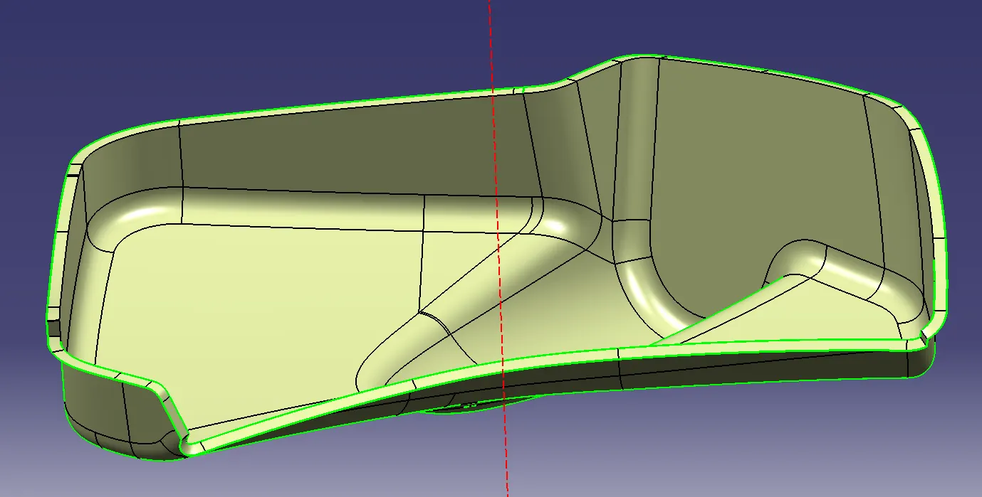
CLASS A&C OF LOWER SUBSTRATE :
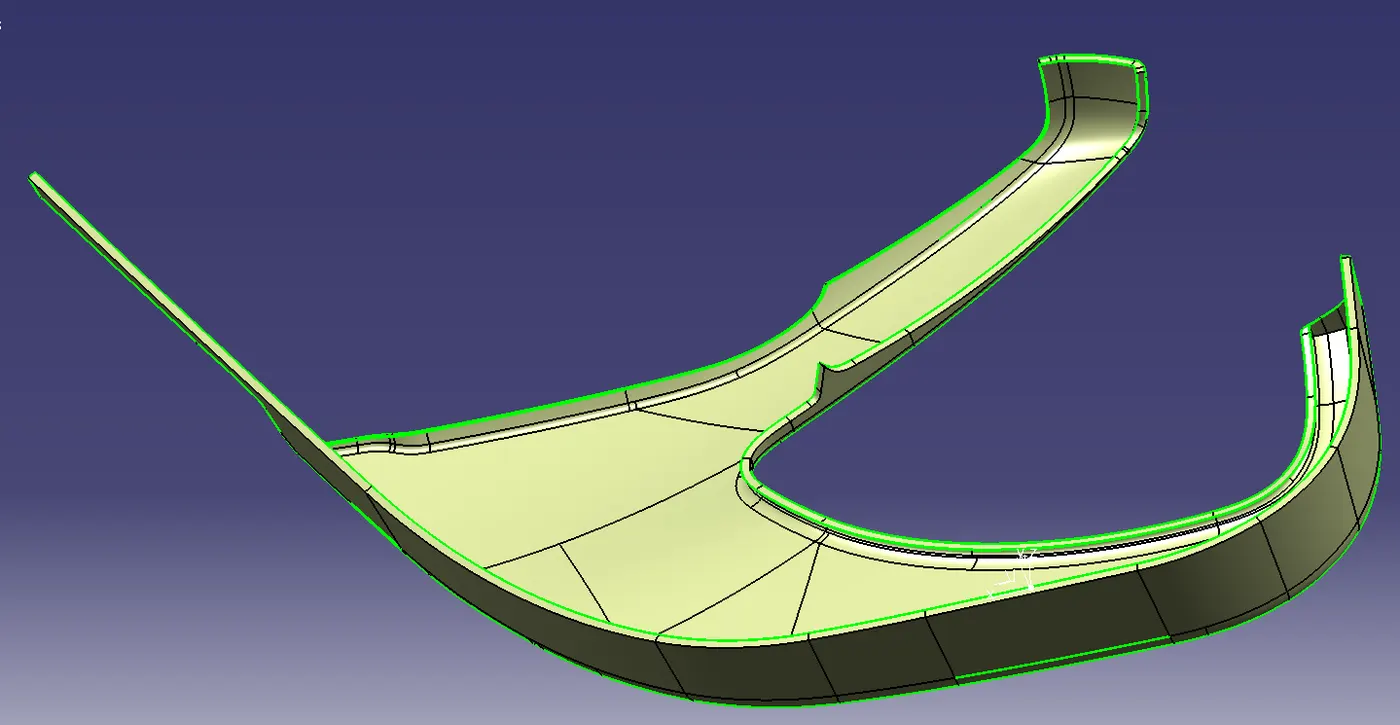
CLOSED BODY :
Trimming class A&C surfaces with class B surface gives final closed body.edges of class b surfaces would have to be extrapolated to intersect with class c surface . giving draft angle to class c surface is the reason for gaps between class c and b
ARM REST CLOSED BODY :
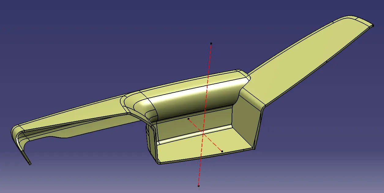
MAP BOX CLOSED BODY :
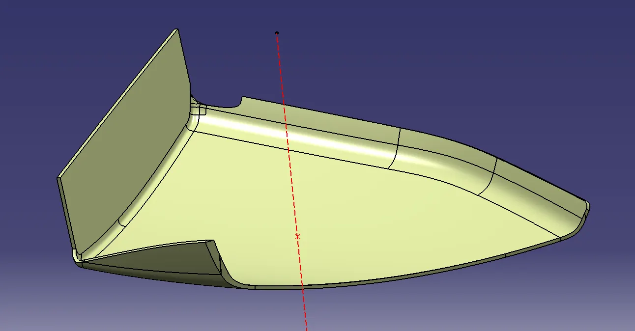
CLOSED BODY OF LOWER MAP BOX :
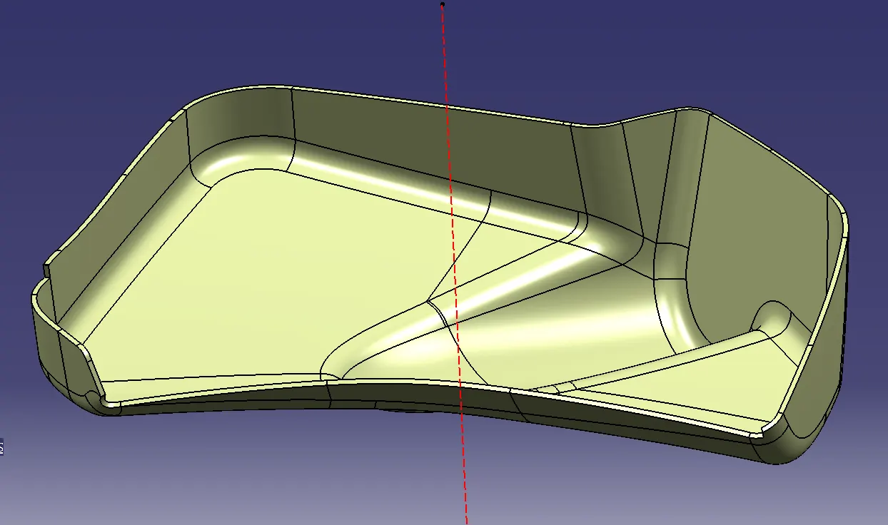
CLOSED BODY OF LOWER SUBSTRATE :
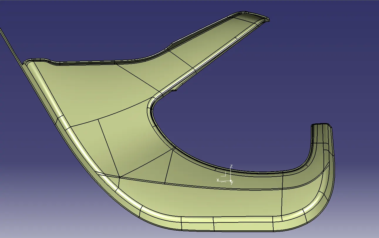
SOLID BODY :
Moving to part workbench from shape workbench, open a part body and select close surface command and select our final trimmed closed surface,thus our output as solid surface is obtained.sometimes it may show any error processing, this may be due to any minor gaps or holes in closed surface. this issue can be checked from the shape workbench itself by trying to creating a boundary of our final closed surface. in ideal condition there wont be no boundaries for a closed surface. if boundary is made ,then the boundary indicates the gaps
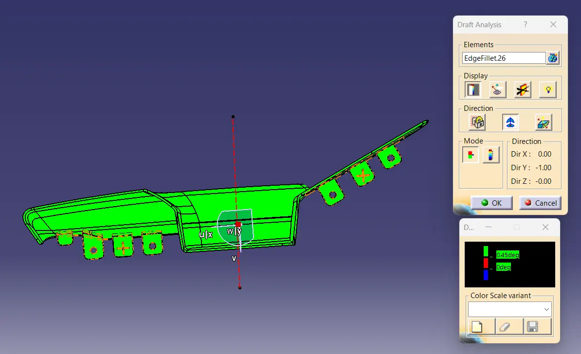
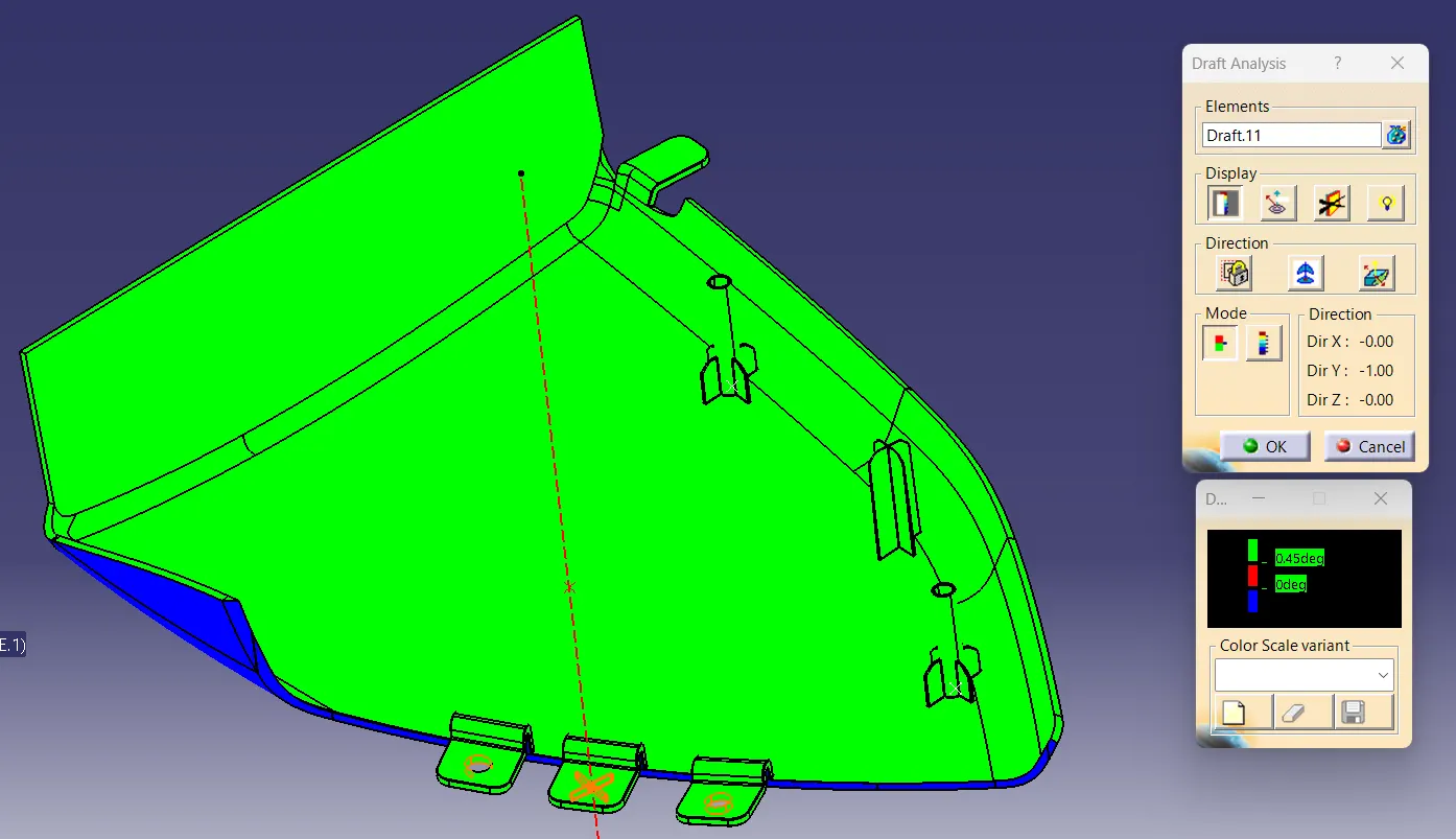
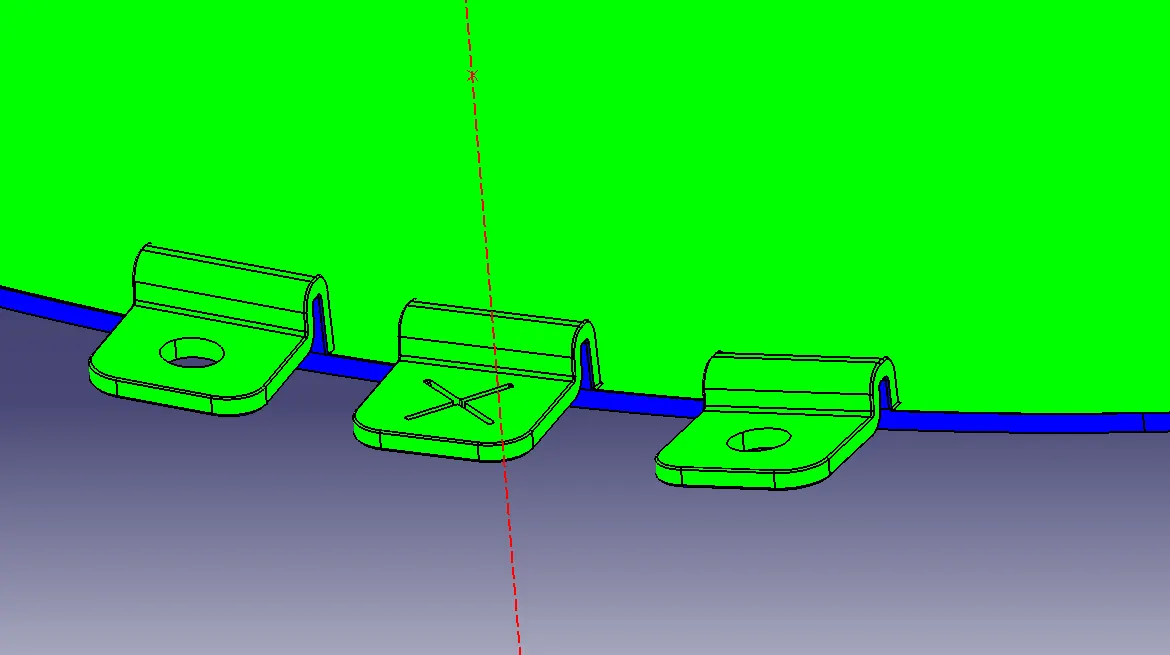
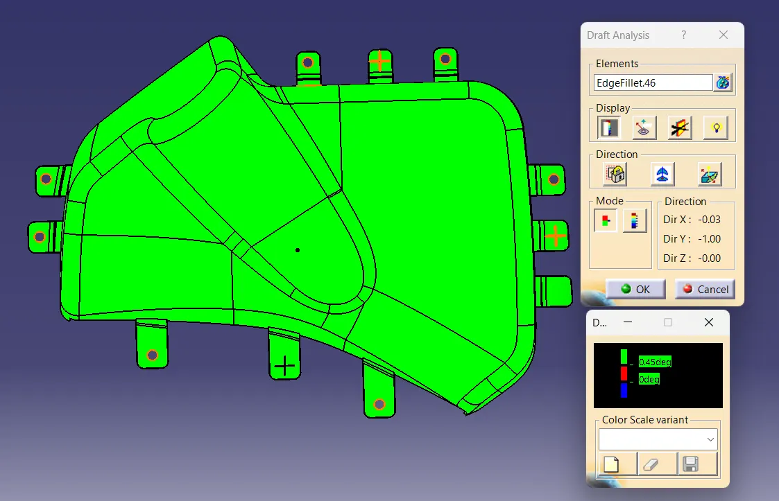
DRAFT ANALYSIS ON SOLID BODY:
conducting draft analysis on solid body enables us to know how the final compnent will perform on moulding process and the quality of our class C surface. sometimes whole surfaces may not clear within draft angle which is 3 degree,so lower the angle of analysis max upto a level of 2.5 degrees. if any of the class C surfaces are not clearing even within the reduced draft angle then it have to be reported to the higher authority .
DRAFT ANALYSIS ON SOLID ARM REST :
Respecting main tooling axis :
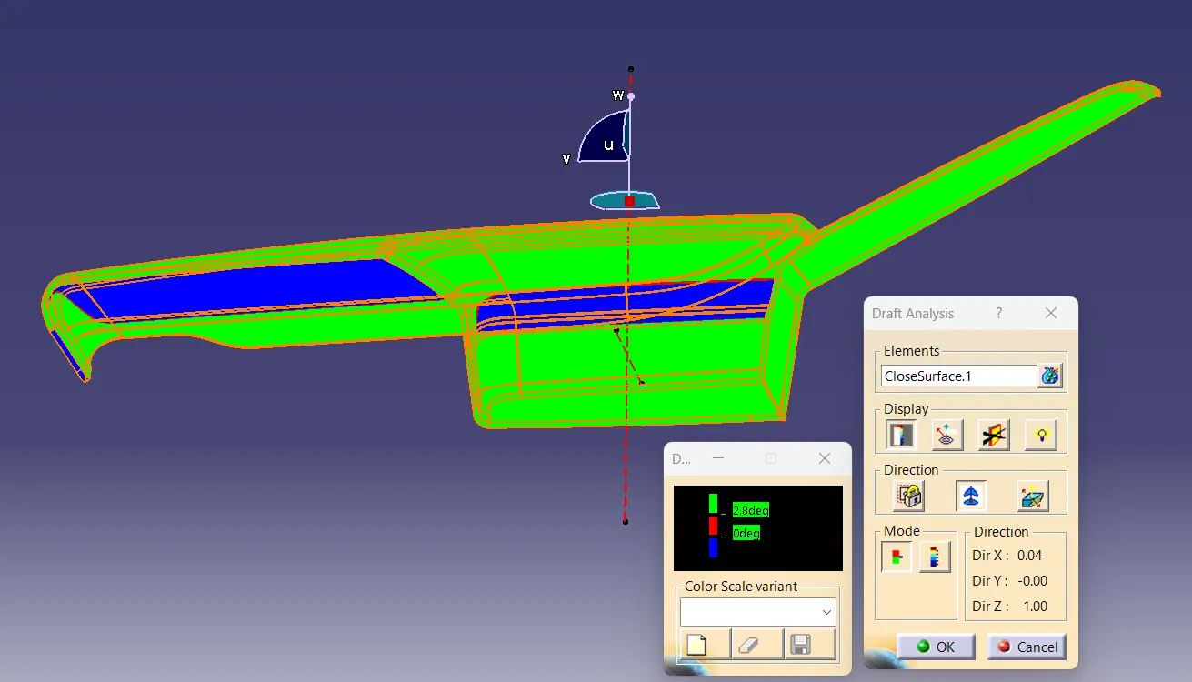
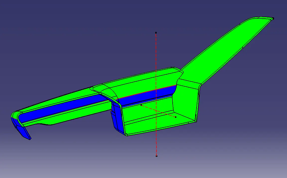
except some class c surfaces, all other faces are clearing.
respecting side core axis :
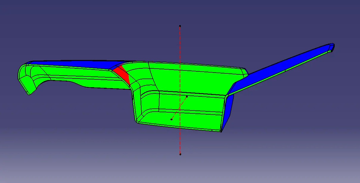
faces which were not clearing on main tooiling axis draft analysis are cleared in side tooling axis draft analysis.this is because the design of class a surface
DRAFT ANALYSIS ON SOLID MAP BOX :
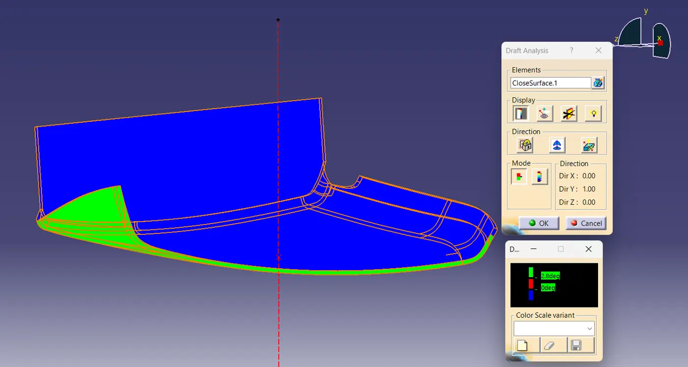
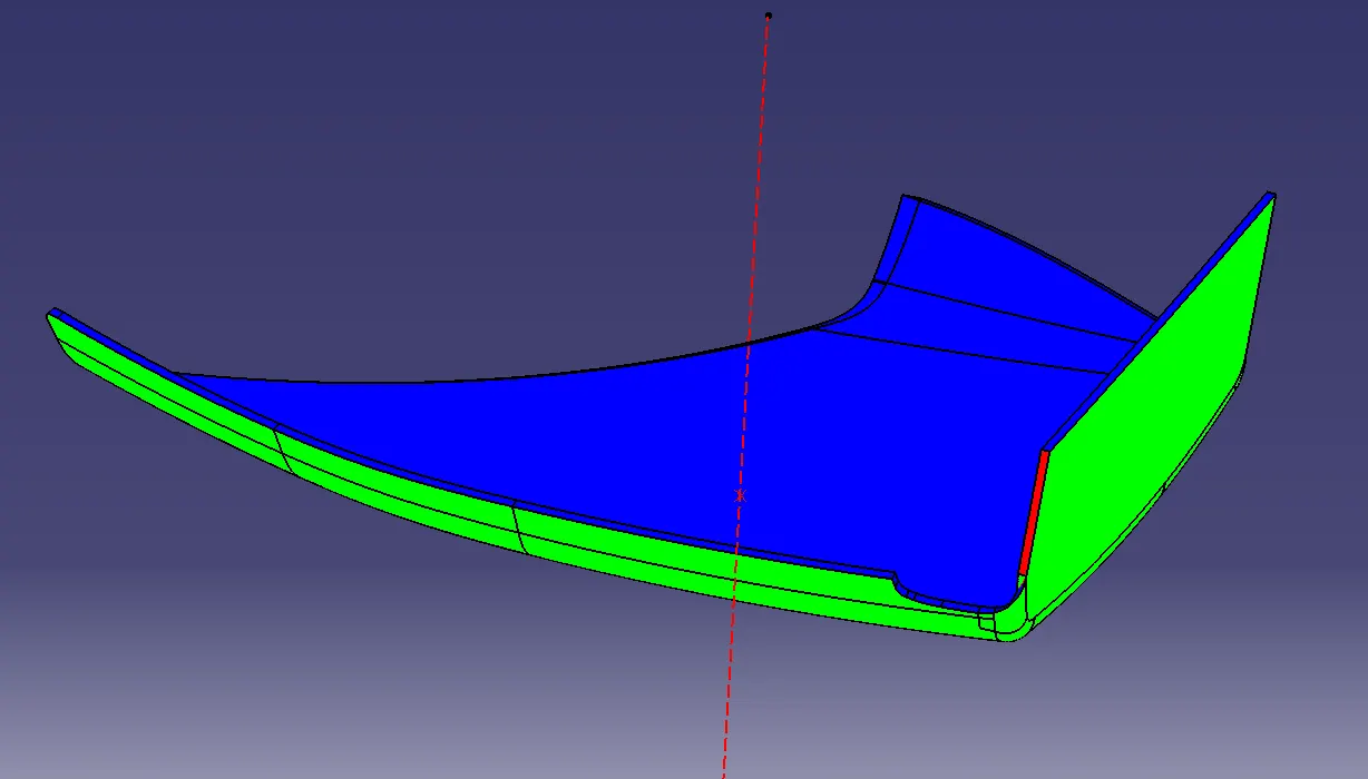
Some faces arent clearing within the draft angle , so this need to be discussed with class a stylist for improvements in class a
DRAFT ANALYSIS ON SOLID LOWER MAP BOX :
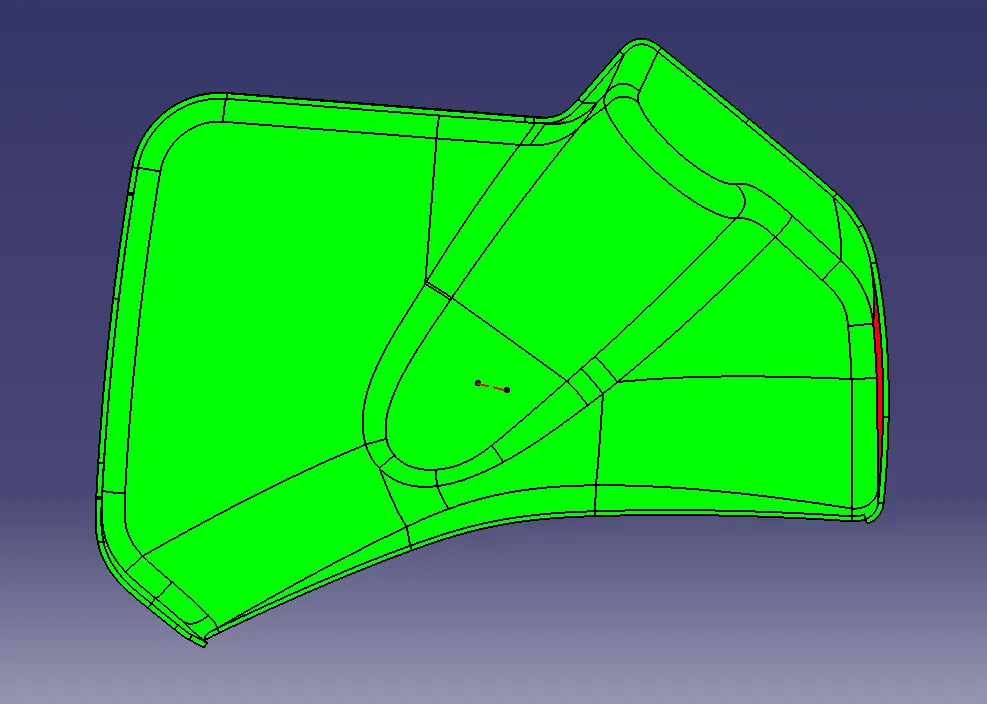
all the class c surface is clearing within the draft angle
DRAFT ANALYSIS ON SOLID LOWER SUBSTRATE :
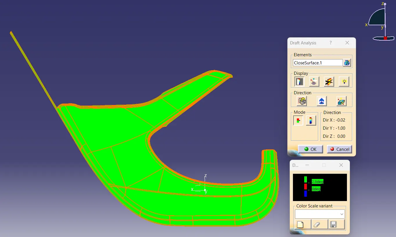
All the class c surface is clearing within the draft angle
B SIDE ATTACHMNET FEATURES :
After working on building class c and class b surfaces on each class a surfaces,all the seperated solid components can be opened in an single assembly workbench.
As mentioned in the objectives, we use push pins with dog house for lower substrate and heat stakes for attaching part to part. for dimensions of the features we follows the given mastersections.
flanges are needed to be built in part edges inorder to attach between parts using heatstakes.
CREATION OF FLANGES :
- class C of component where flange is desired to be placed is extrapolated to an certain value.
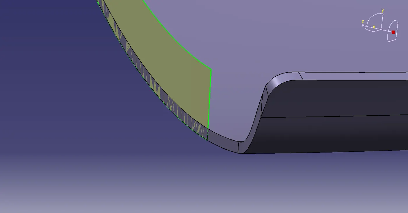
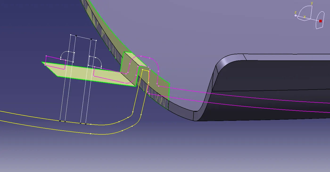
- created a plane normal to the edge curve and opened a positioned sketch
- drew the shape of the flange as guided in the master section and extruded
- trimmed both surfaces together
- moved to part workbench and opend a body
- chose thicken command and selected the trimmed surface
- extracted an edge perpendicular to class c and extruded in tooling axis direction in shape workbench
- took an offset of this extruded surrface to an value which desired to be the width of the flange
- coming back to part workbench,select split command and select created surfaces to trim off the sides
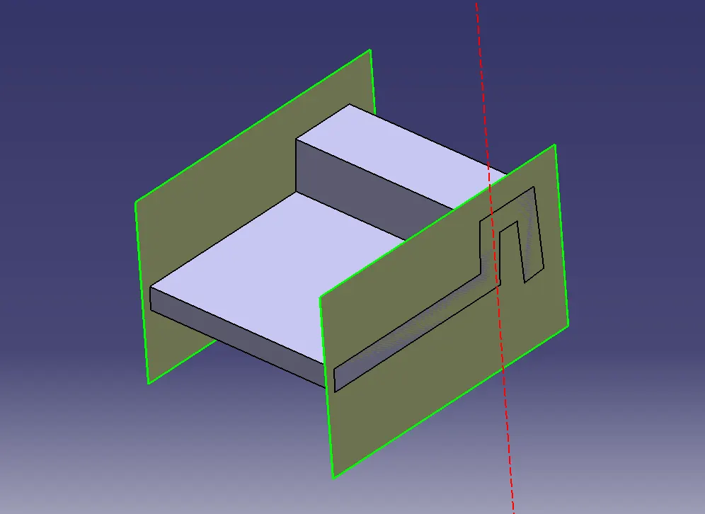
- drew a circle on centre of the flange face with radius specified in mastersection
- extruded the circle in a new body in part worbench
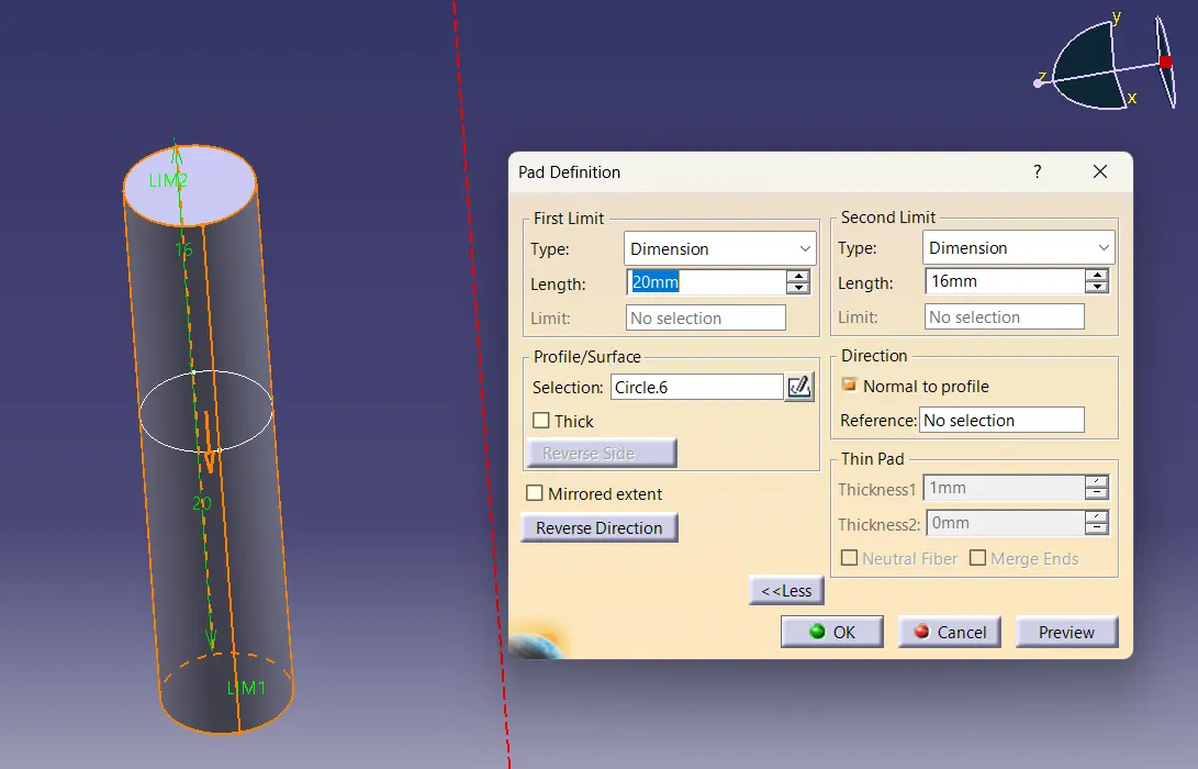
- removed this body with flange partbody
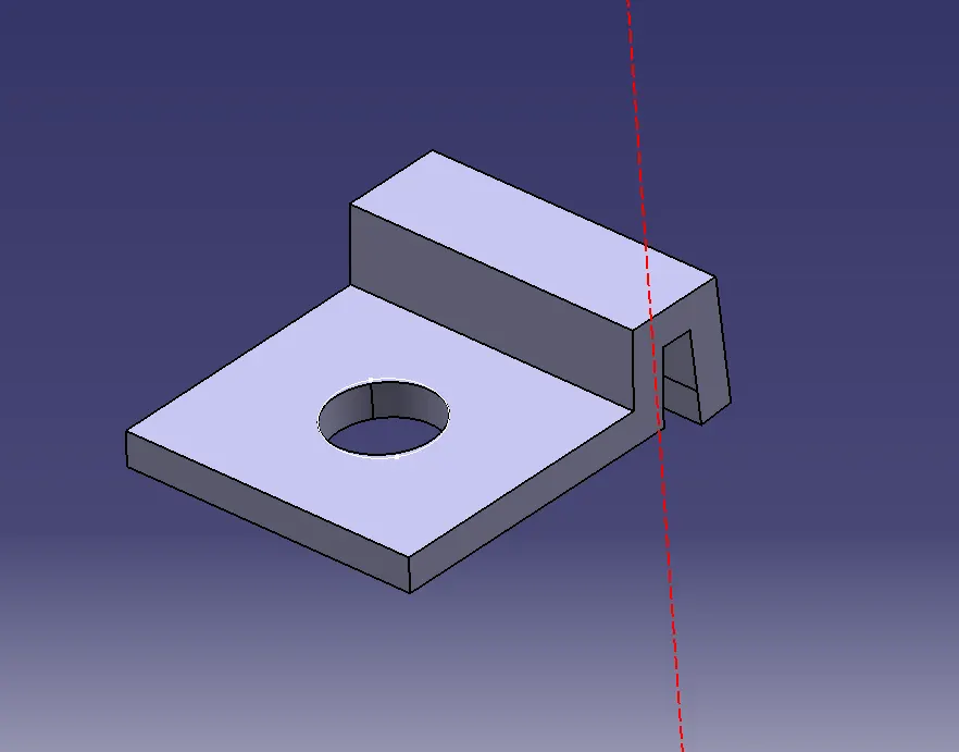
- chamfered outer edges of flange to 45 degree
- filleted edges with 3, 0.5 and 0.25 degrees
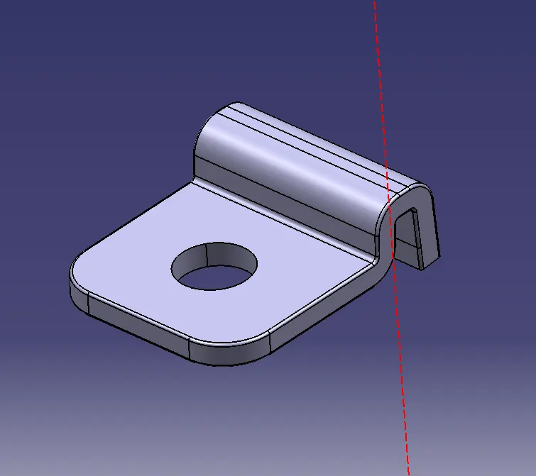
- added this partbody with main partbody
HEAT STAKES :
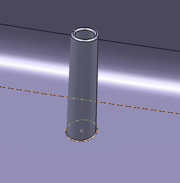
Heat staking also known as thermoplast staking is a process of joining two dissimiliar materials together . it is a kind of welding thus, it is a permanent joint.one part holds the holes and other posses the projections which are to be placed inside the holes.by enabling localised heating,the projected part is allowed to reform. this projected part is called heat stakes. heat stakes are a hollow tubes drafted inside and out.
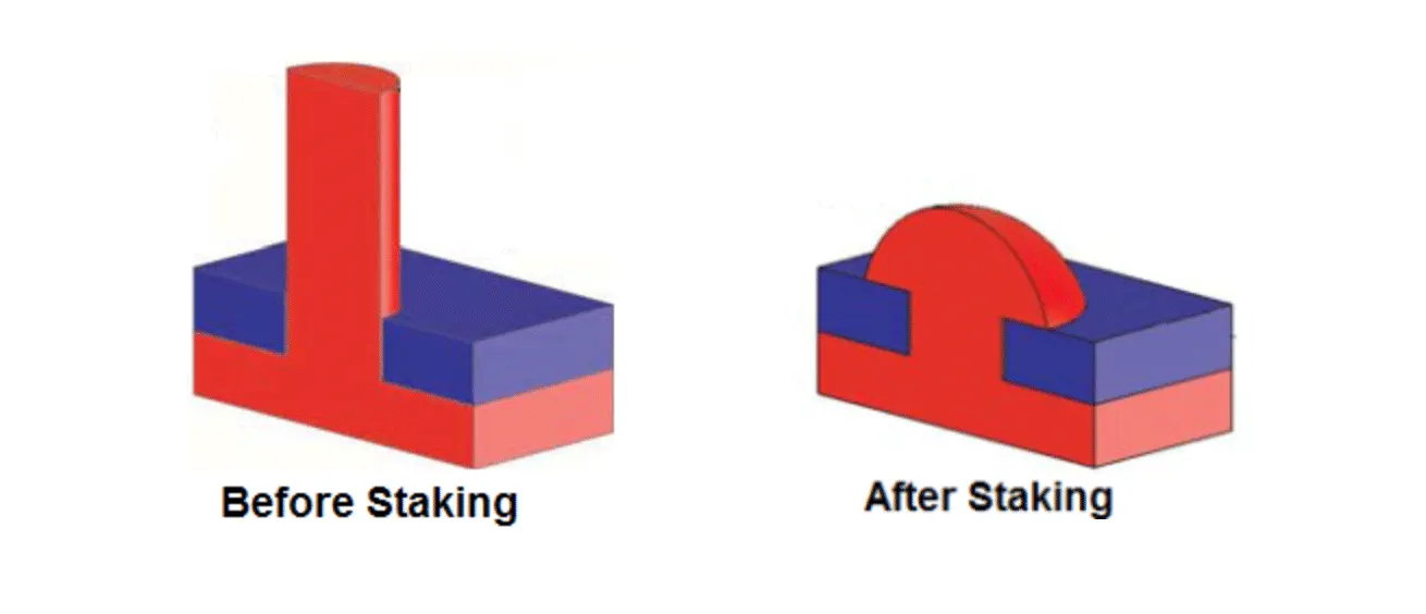
BENEFITS :
- simplification of machinery
- reduces cost of machinery
- multiple fastening points
- allows higher density of weld compared to hot air cold form or ultrasonic welding
CREATION OF HEAT STAKES :
- Created points on the surfaces which heatstakes are proposed to be placed
- drew circle concentric to the points on ZX plane.
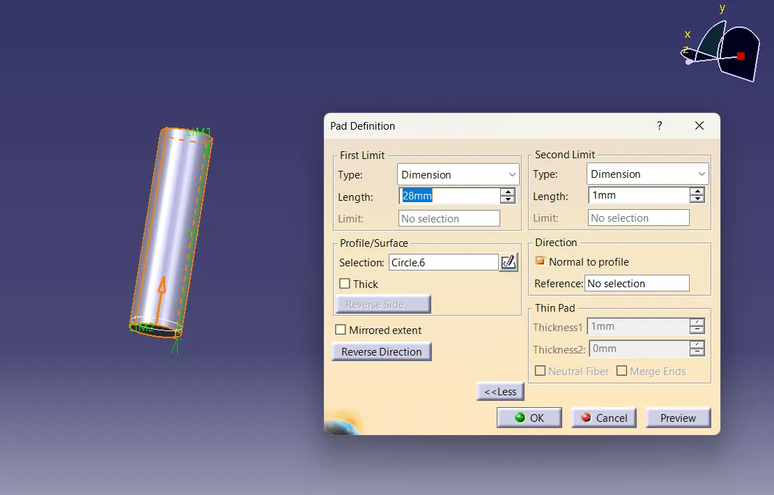
- padded the circle in part workbench in seperate part body
- ensured to provide a 1 mm second limit
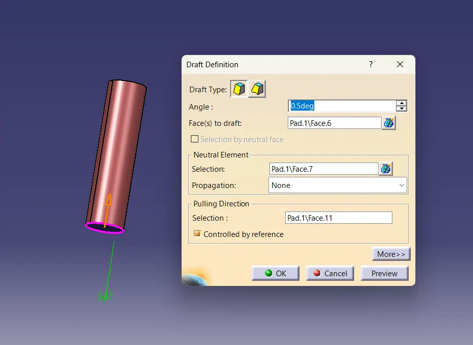
- drafted the outer and inner walls of the part with 0.5 degrees
- copied the partbody and paste special in same part file, then translated to next proposed point
- repeated this procedure until last point.
- assembled all the heatstake partbodies into a new partbody and union trimmed this part body with main part body
- gave fillets to the edges
RIBS :
Ribs are structural features which are added to the internal walls of the moulded components to provide strength and stiffness. thin walls perpendicular to the components with drafted faces could increase its strength offered propotional to its thickness
DESIGN PARAMETERS :
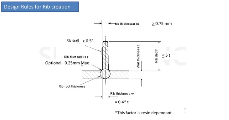
- Draft: 0.5 Degree per side (minimum) and maximum upto 1.5 degrees
- Thickness of ribs: 40 to 50% of wall thickness
- Height: ≤ 5 times the wall thickness
- Spacing (for more than 1 rib): 3:1- steel height/width ratio (maximum). h/w =3 or2(preferred) where h is the height of the rib and w is the space between two ribs.
- Minimum thickness at the tip: 0.75mm
- Rib fillet Radius: 0.25mm max or 0.125*thickness of the component
- Rib root thickness should not be more than 30% of the wall thickness.
CREATION OF HEATSTAKES RIBS :
- opened position sketch referring ZX plane and centre point of heatstake
- drew out line sketch of ribs
- open a part body in part workbench and pad the sketch upto desired height
- select thick option and neutral fiber
- ensure to provide atleast 1 mm second limit
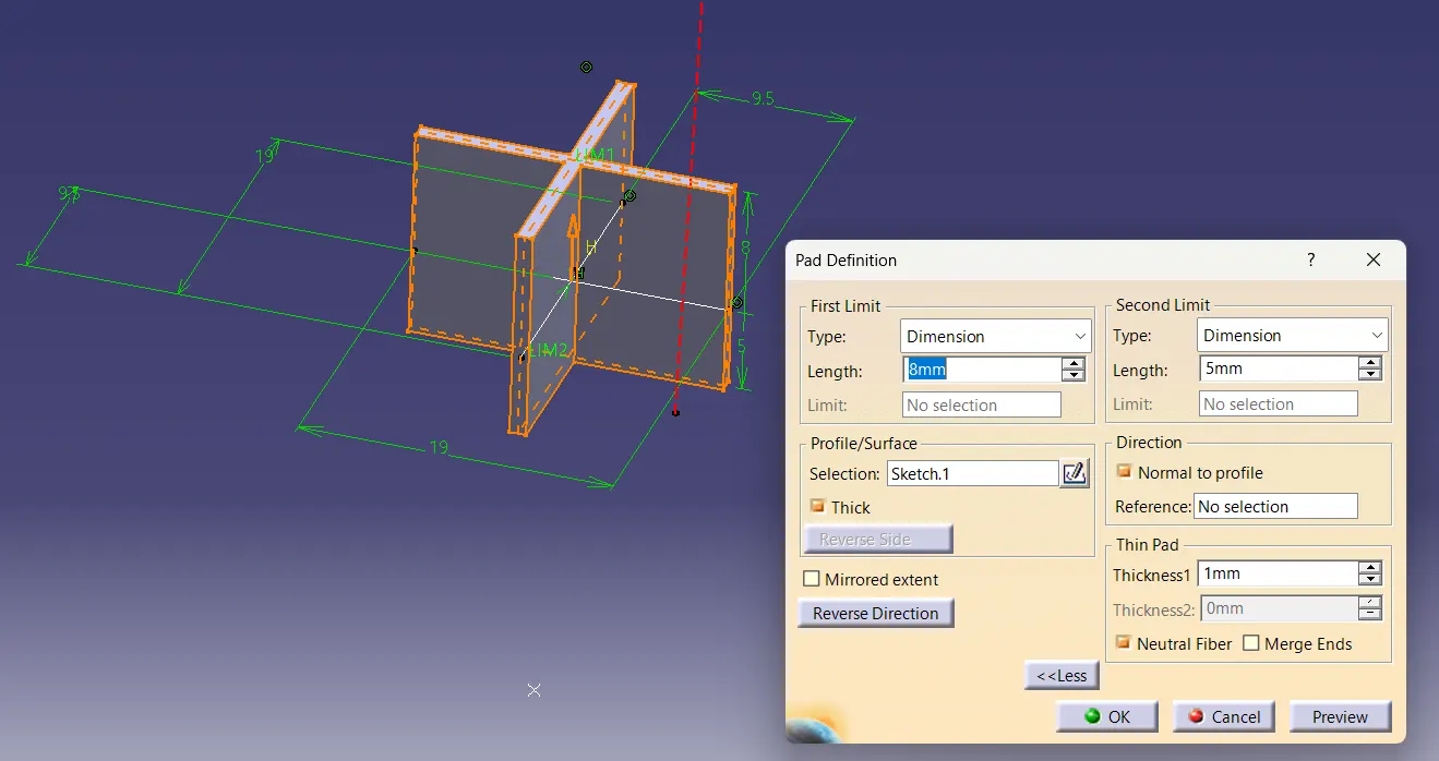
- draft the sides if ribs with 0.5 degree to tooling axis
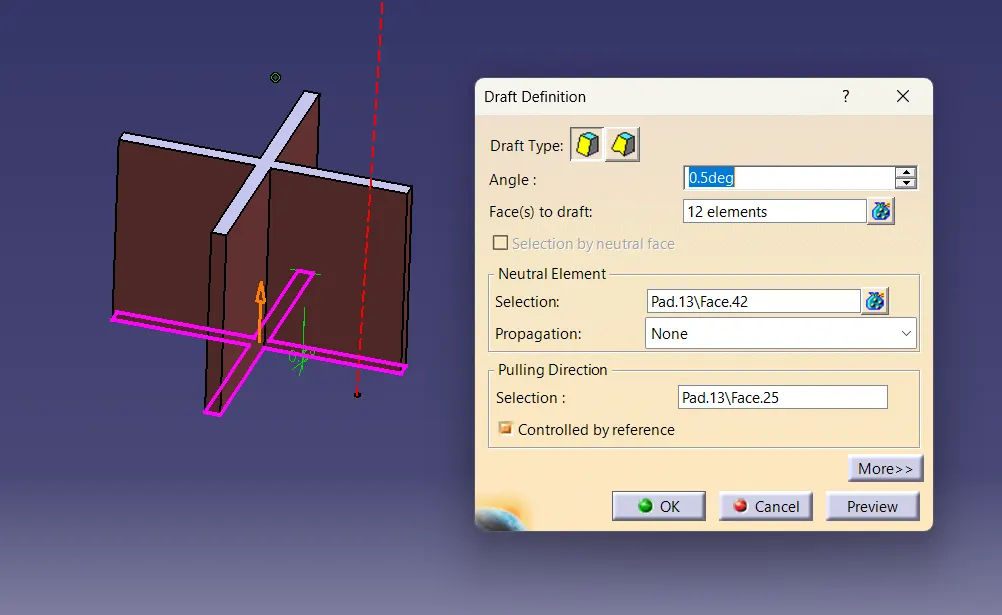
- chamfer outer edges to 45 degrees
- fillet remaining edges
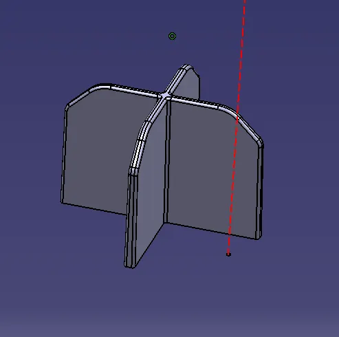
- copy the part body and paste special in the same part file opting result with link
- translate copied part body to desired point
- continue this copy paste procedure until fulfilling the need
- assemble all the part body into another part body and add this body with heatstakes part body
LOCATORS :
Locators are used for locating one part on another while joining them together. so it should be the one to comes in contact first while joining 2 components, also it is the duty of locators to arrest freedom of movements between the joined parts. a body has totally 12 freedom of movements, forward and backward movement along X,Y & Z and forward and backward rotation along X ,Y & Z. there are basically two types of locators, 4 way and 2 way
a four way locator arrests the freedom of movements of a body in 4 ways and 2 direction in a plane (X+ ,X- ,Y+ ,Y-)
a two way locator arrests in 2 ways and 1 direction in a plane (X+ ,X-)
same design parameters of ribs are followed
CREATION OF LOCATORS :
- create points where locators are proposed to be placed
- open a positioned sketch on reference to the XZ plane and projection point with one of the points created
- draw outline sketch of the locators
- pad the sketch in part workbench in a seperate part body
- select neutral fiber and thick option
- ensure to provide atleast 1 mm second limit
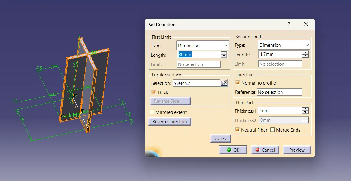
- give 0.5 degree draft to the vertical walls of the locator with tooling axis
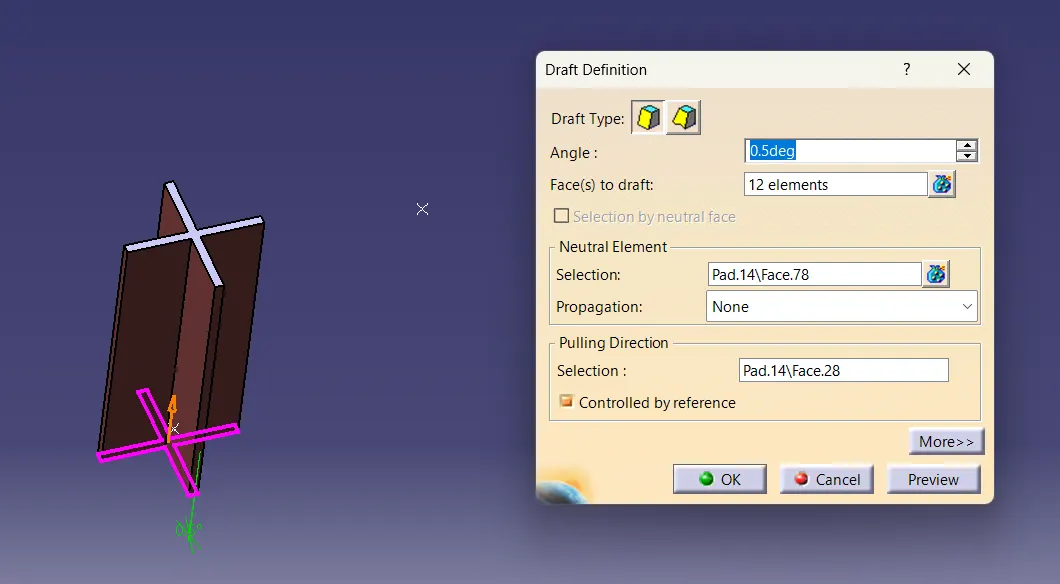
- chamfer the outer corners to 45 degrees
- fillet all the edges
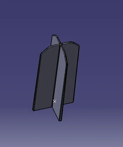
- copy the product file and paste special in the same file
- then translate copied product to next destined point
- ensure the locators projects higher than any other attachment features on the component
- assemble all the part bodies into another part body and union trim them with main part body
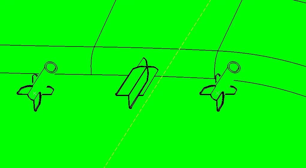
DOG HOUSE :
Doghouse is an engineering feature used in the plastic trim design which helps to remove sink marks formed on Class-A surface while creating attachment feature on Class-B surface. Doghouse is a supporting feature, other features like locators, heat stakes, pushpins are mounted on top of doghouse for fixing and assembly purpose.it solves length issue by placing attachment features on top of it . Doghouses are subjected to draft analysis to prevent breakage of the component during ejection from the mould.
DESIGN PARAMETERS :
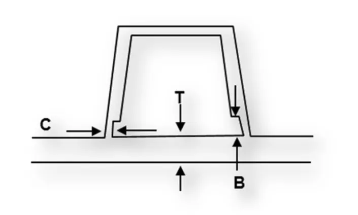
- Doghouse wall thickness at the intersection of the part wall (C) should be 40% or less than the main wall stock (T).
- The height of ( B ) should be between 3.0 – 6.0 mm
- Outer surface of dog house must have a draft angle of 3 degrees
- Inner surface of dog house must have a draft angle of 0.5 degrees
CREATION OF DOG HOUSE :
- Opened a positioned sketch on refernce to ZX plane
- drew outline sketch of the dog house with desired values
- extruded the sketch in shape workbench
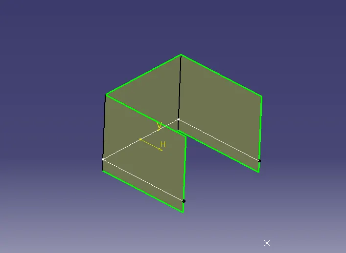
- created a line parallel to zx plane in the same plane and extruded it
- offsetted this created plane as to the height needed for the dog house
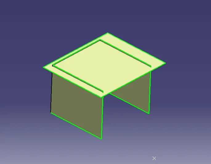
- trimmed them together
- opened a new part body in part workbench and thickened this trimmed surface using thickening command
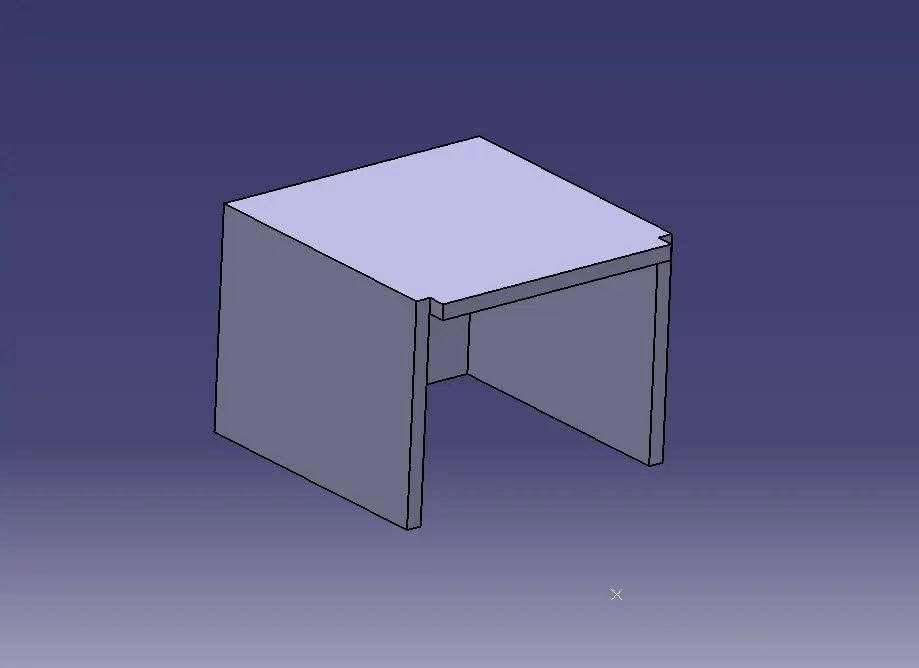
- extracted the rear surface of the trimmed surface and offsetted forward to length needed for the dog house
- splitted solid dog house using this offsetted surface in part workbench using split command
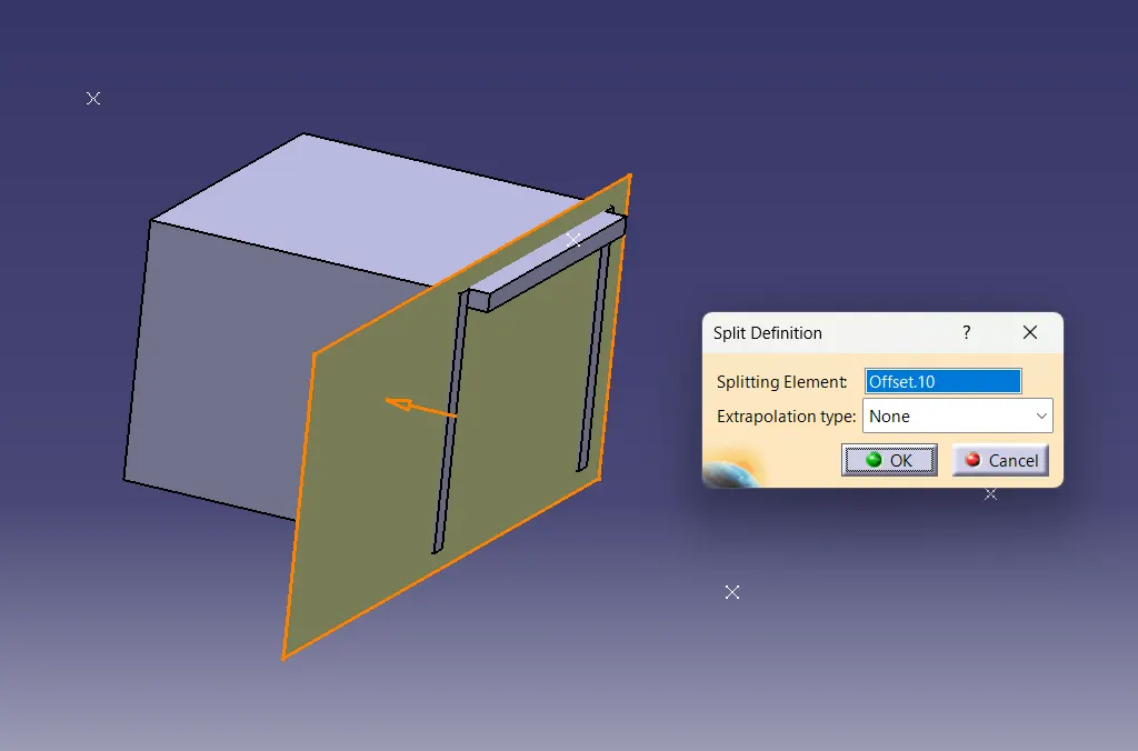
- drafted all the outer surfaces to 0.5 degree with main tooling axis
- filleted outer edges
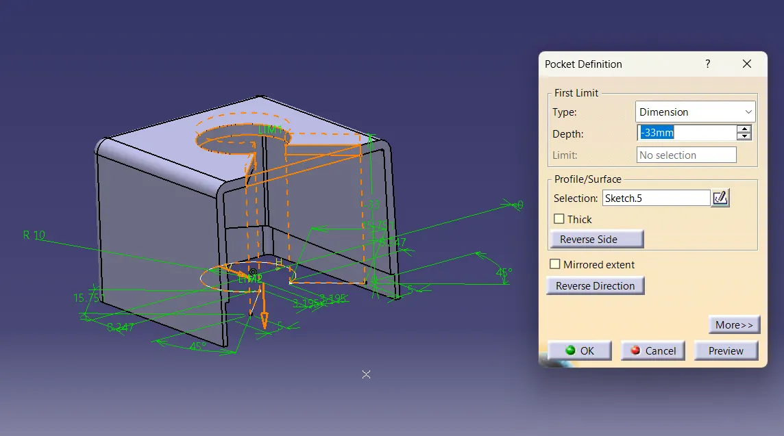
- opened a positioned sketch selecting top surface of doghouse as support and projection point as mid point of the top surface
- drew sketch of the top hole needed
- selected pocket option in part workbench and created top hole
- opened another sketch on refrence to YZ plane and projection point as mid point of rear surface of dog house
- drew sketch of inner part
- padded it in seperate part body

- extracted dog house floor surface and vertival walls of dog douse
- offsetted vertival walls outside direction for 1 mm
- offsetted floor surface between 3 to 6 mm
- trimmed them together and splitted the solid dog house with this surface in part workbench using split command
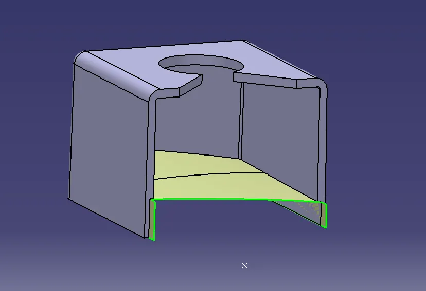
- drafted trimmed faces
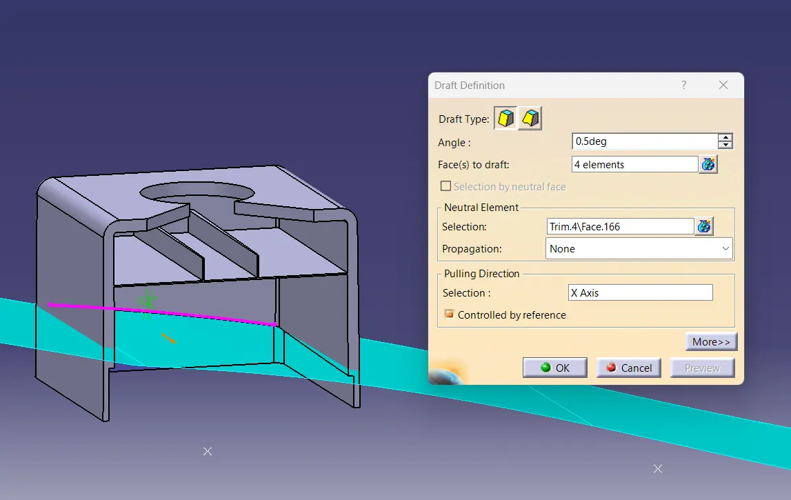
- created side core axis perpendicular to main tooilng axis
- drafted inner part walls and inner surfaces of dog house with respect to side core tooliing axis
- union trimmed this part body with dog house part body
- filletted all the sharp edges
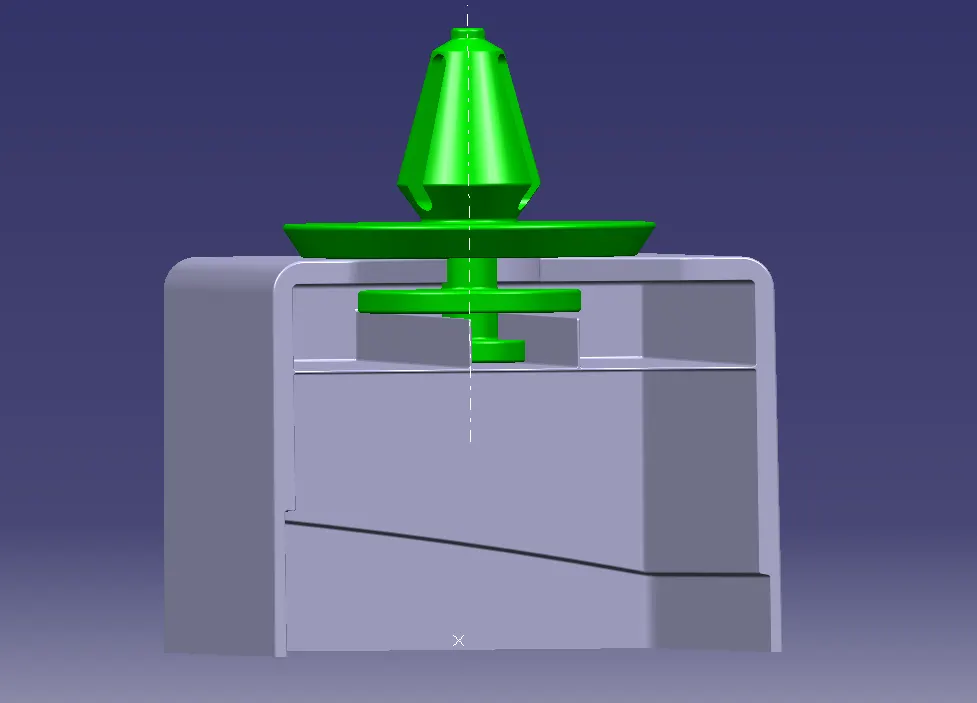
- copied the part body and paste special with the same file
- translated to other destined points
Later push pins are placed inside the doghouse in assembly worbench using surface contact constrain and coincidence constrain
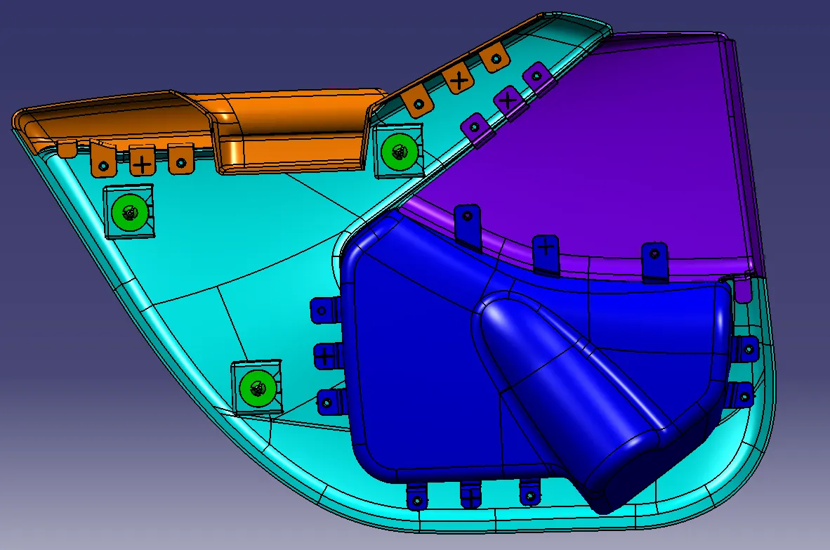
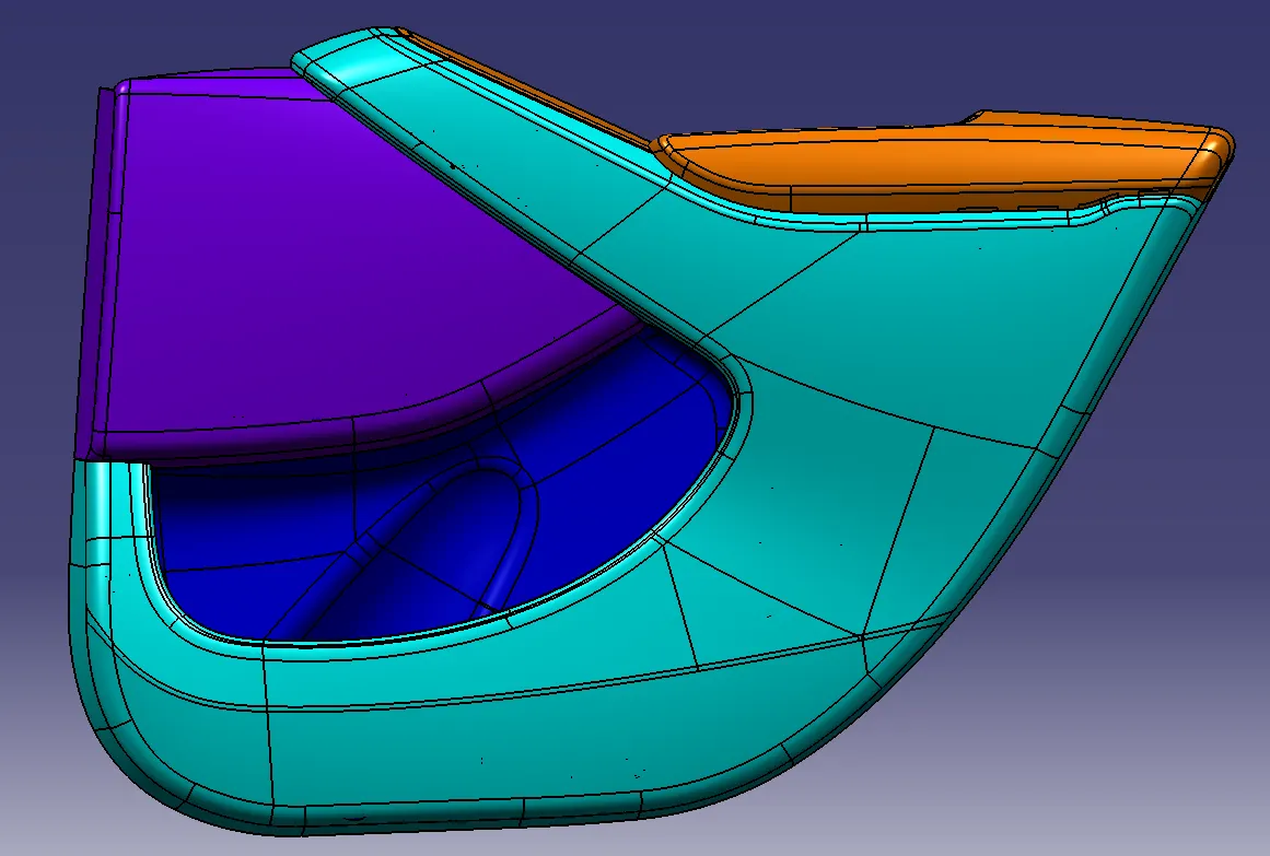
All the door panel components are attached to lower substrate by means of heat stakes and final door panel complete work is proposed to attach using push pins which are placed in lowersubstrate dog house
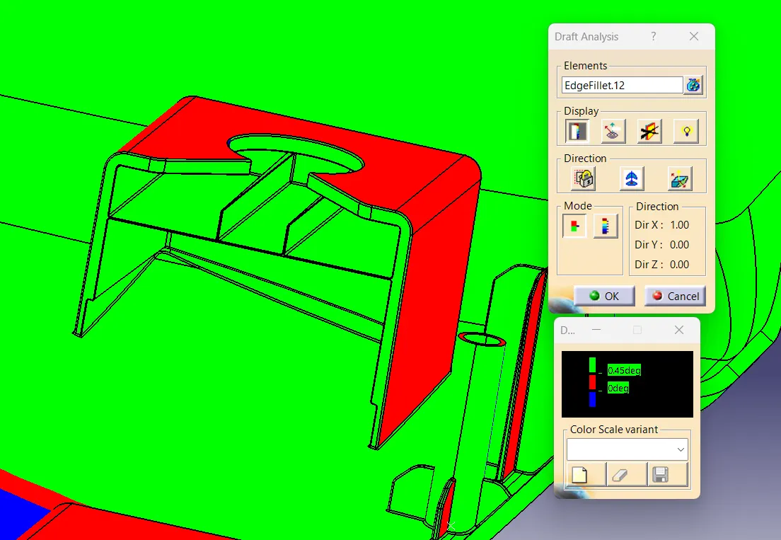
DRAFT ANALYSIS ON FINAL SOLID COMPONENTS :
ARM REST :
Respecting main tooling axis :
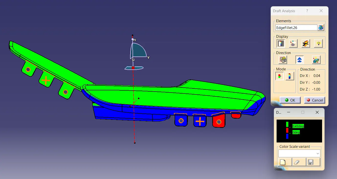
Respecting side tooling axis :
MAP BOX :
LOWER MAP BOX :
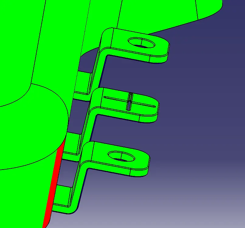
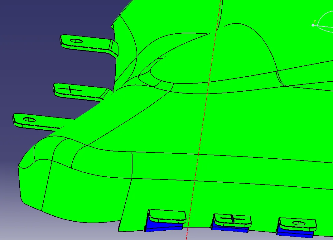
LOWER SUBSTRATE :
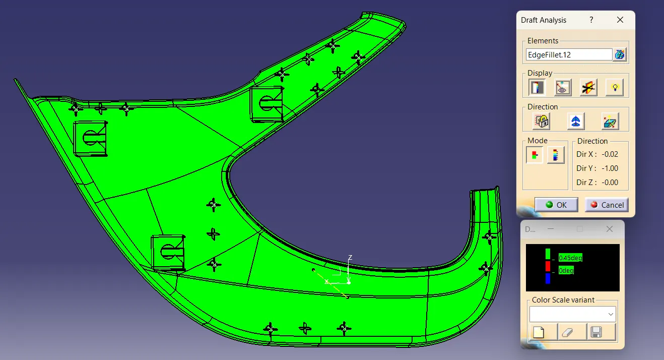
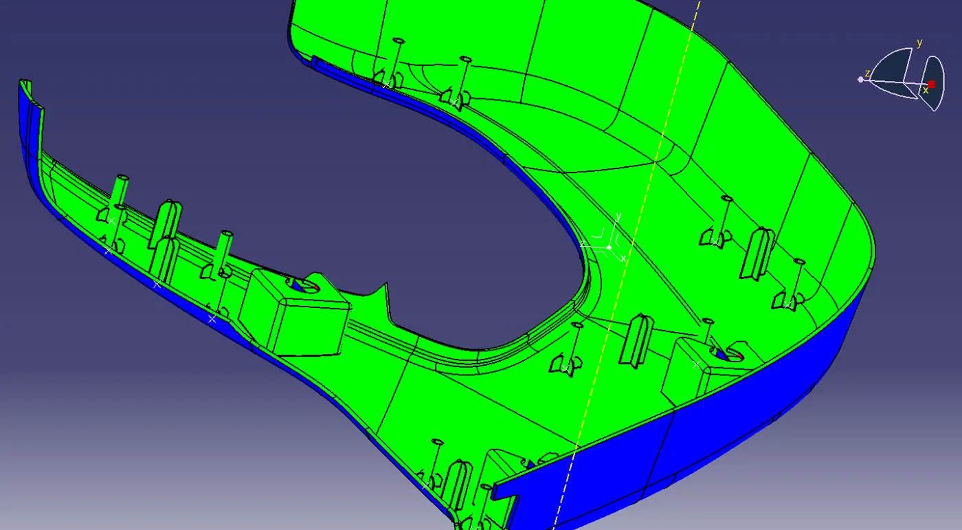
DOGHOUSE :
DOOR PANEL COMPLETE WORK :
IN SHADED WITH EDGES MODE :
IN SHADING VIEW MODE :