Base Bracket Design
TOOLING AXIS CREATION
Tooling axis is the axis in which the core and cavity moves. Draft for easier ejection of the component is incorporated on the core and cavity with reference to this tooilng axis. 3 degree is the nominal draft angle and 7 degree for textured surfaces.
Z direction for tooling is selected by visual inspection because, largest surface and a hole is in Z plane.
created a dummy tooling axis through centre point of a hole
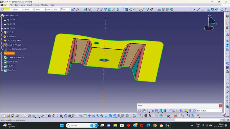
created a plane through centre point of the hole parallel to yz plane and intersected the plane with A surface
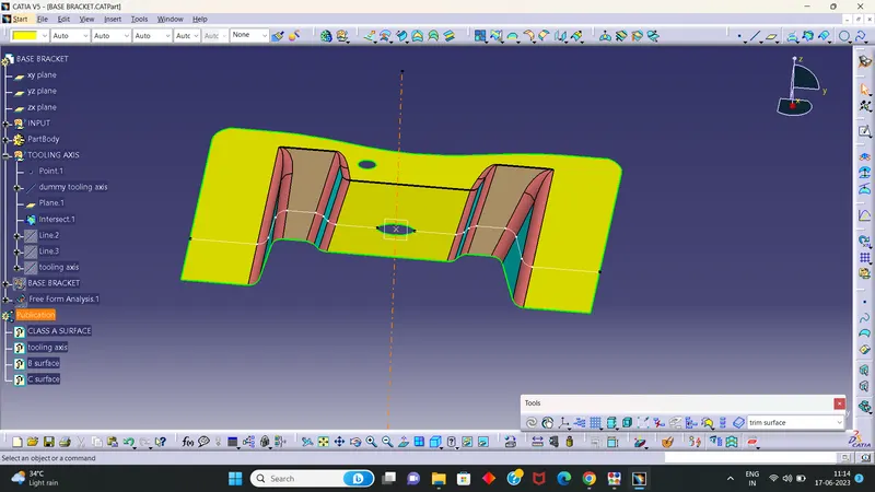
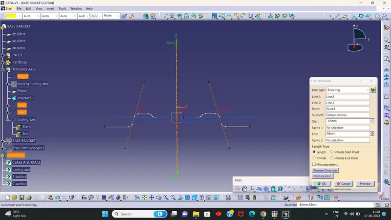
extended 2 inclined lines of both sides of intersection and created a bisecting line . this is the tooling axis
DRAFT ANALYSIS
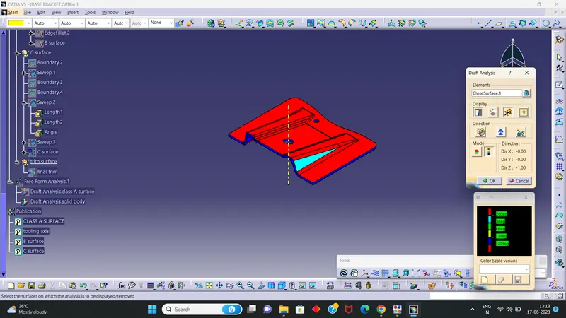
Draft analysis is done by identifying the zones represented by different colours which indicates the range of drafting angles of surfaces
selecting insert,analysis,feature draft analysis from tool bar, draft analysis begins.
using the compass tool,place the compass on the object in line with the tooling axis .
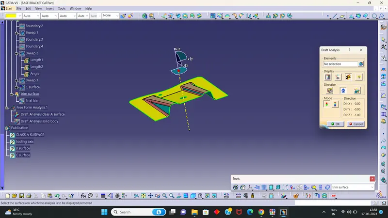
then with lock tool,lock the compass.selecting display tool, new window of colour varients corresponding to angles opened.by clicking on the A surface the elements on the surface which are in the limit of 3 degree draft angle indicates green colour.red indicates 0 degree and blue indicates negative degree angles
DRAFT ANALYSIS VIEW OF CLASS A SURFACE
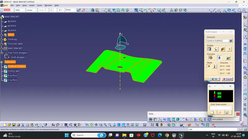
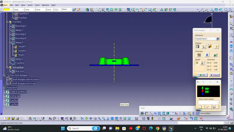
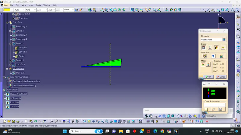
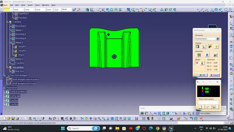
if the surface completely lies within draft angle limits, it indicates fully green as shown in image. then the surafce can be subjeced to further surface creations.
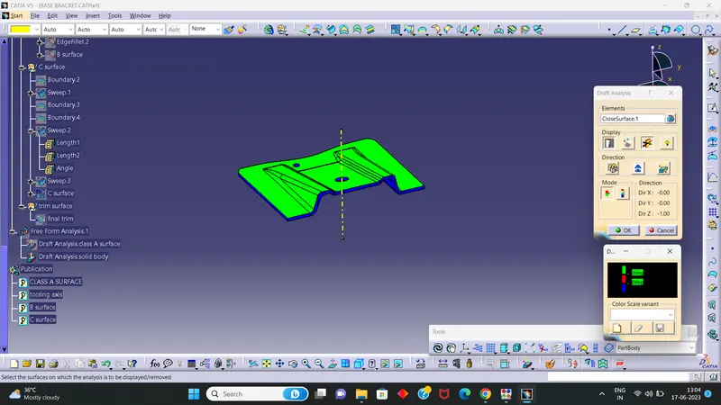
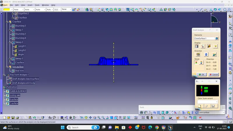
DIFFERENT DRAFT ANALYSIS VIEWS OF FINAL PLASTIC PART
1.
2.
3.
4.
5.
6.