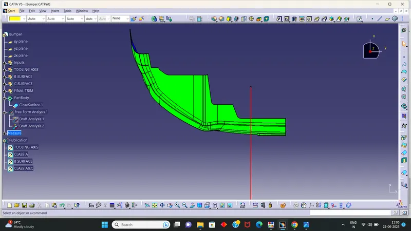
Bumper design
TOOLING AXIS CREATION AND DRAFT ANALYSIS ON CLASS A SURFACE
Visually inspecting the surface and assuming tooling axis in basic X,Y&Z axes. the hollow portions can be cleared in Z axis easily
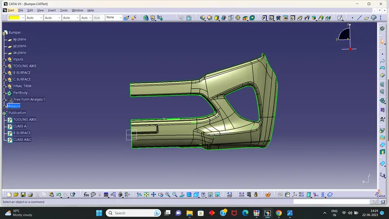
thus created a dummy tooling axis in Z direction by creating a point on the surface .
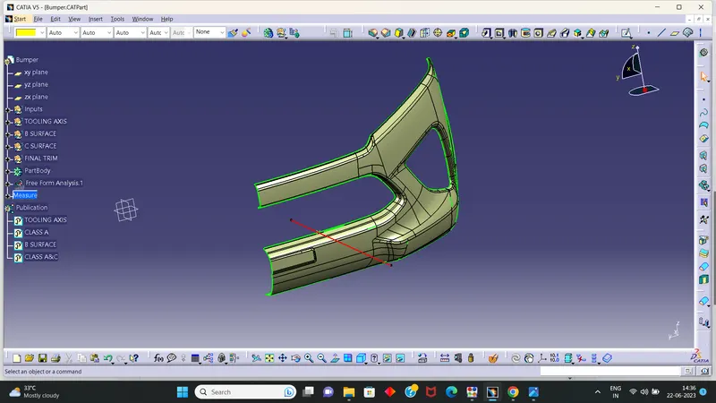
performed draft analysis in class A surface referencing dummy axis by aligning compass on the tooling axis.
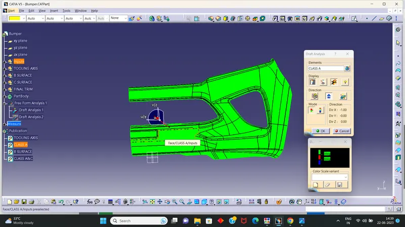
whole surface turns out to be green, thus this dummy axis is taken as the main tooling axis
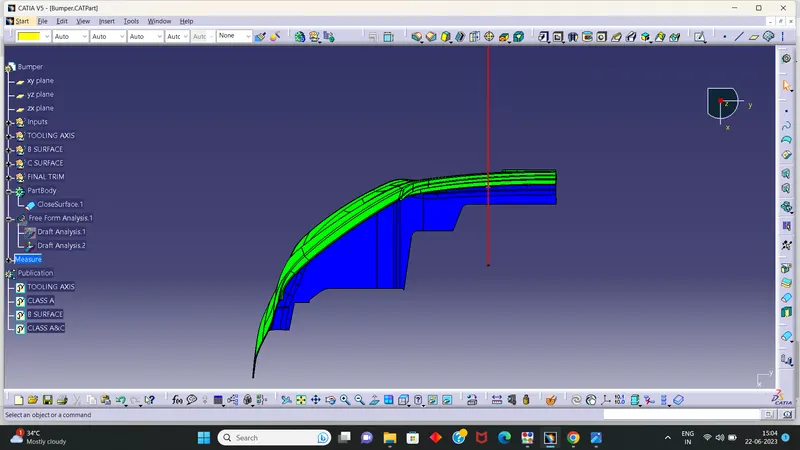
DRAFT ANALYSIS ON SOLID COMPONENT
the compass is placed on the main tooling axis by the help of compass tool, and selected the solid part.
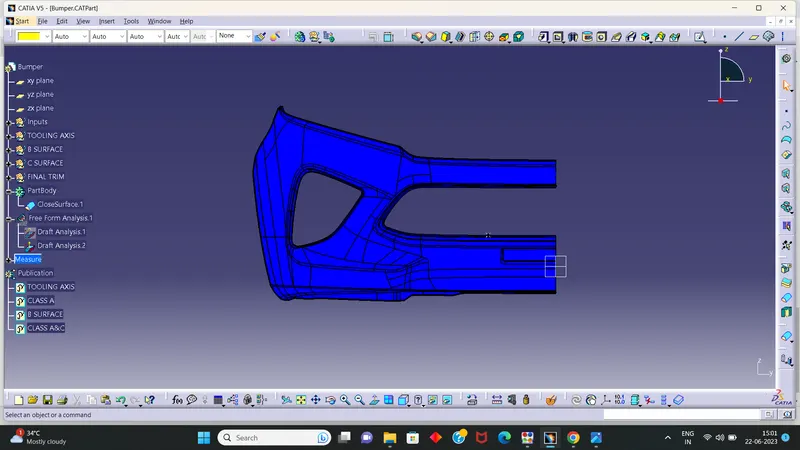
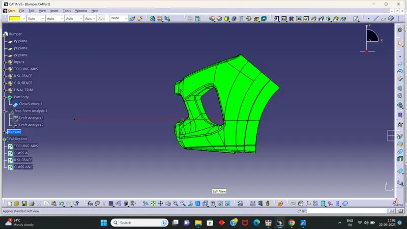
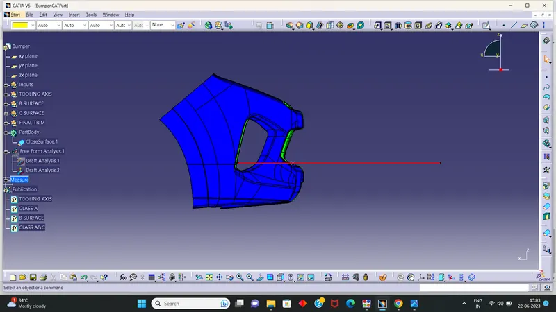
green colour colour indicates the angle within the draft angle, blue indicates negative angle and red indicated 0 degree
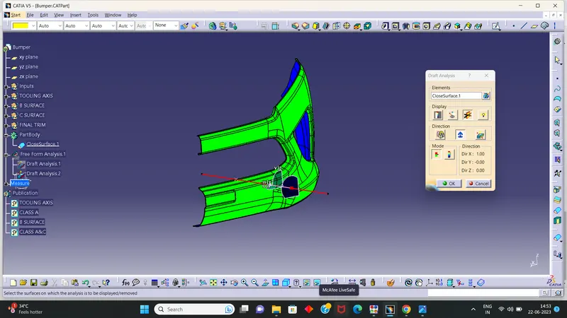
DIFFERENT VIEWS OF DRAFT ANALYSIS ON SOLID COMPONENT
1.
2.
3.
4.
5.