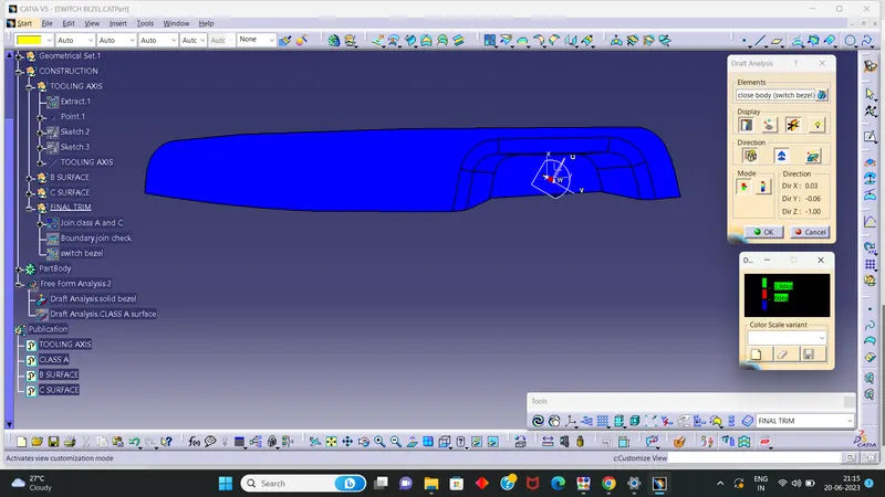
Switch Bezel Design
TOOLING AXIS CREATION:
Extracted the base of the bezel and marked a point on the centre of the surface.then placed an axis system in reference of the point created.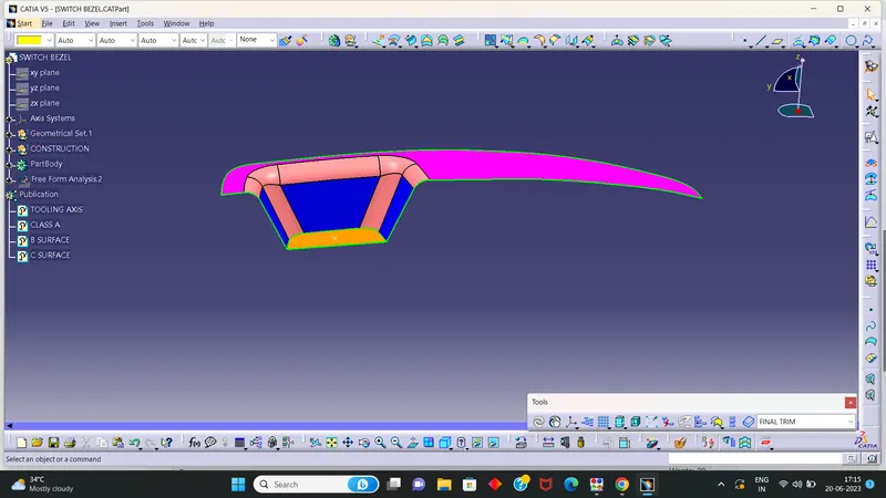
opened a positioned sketch on YZ plane and intersected through the point.
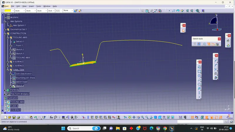
then drew lines coinciding slanded walls of bezel and bisected these two lines. this bisected line is the tooling axis in YZ plane
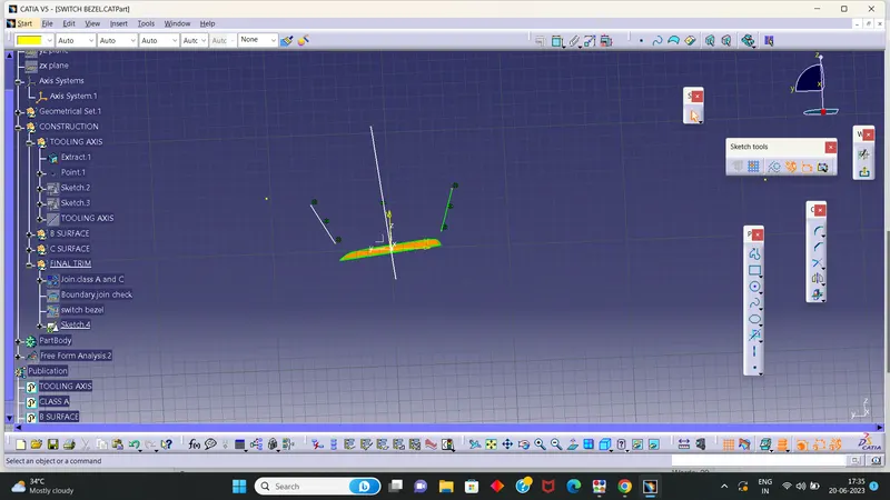
opened another positioned sketch referring XZ plane and intersected through the point along the plane
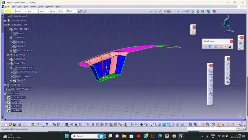
created a line through slanded wall of the bezel. as there is only one face for bezel along this plane, no bisection is needed. instead, a line with 3 degree inclination to the projected line is drawn through the point
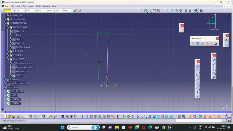
and this line with 3 degree inclination is the tooilng axis in XZ plane
bisecting both tooling axes in both planes obtains the final tooling axis.
DRAFT ANALYSIS OF CLASS A SURFACE
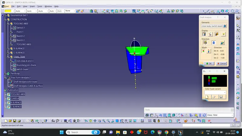
opening draft analysis from tool bar and clicking on the class a surface, draft analysis report indicates on the surface. place the compass coincidng on the tooling axis using compass tool in the window.
green surfaces indicates surfaces within the draft angle, blue indicates 0 degree and red indicates negative angle
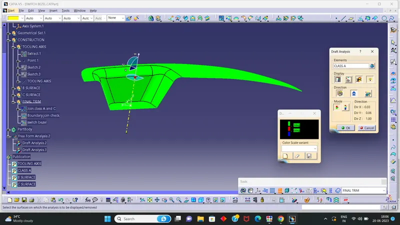
DRAFT ANALYSIS OF SOLID BEZEL
opening feature draft analysis on solid bezel it indicates negative angle on c surfaces and one wall.
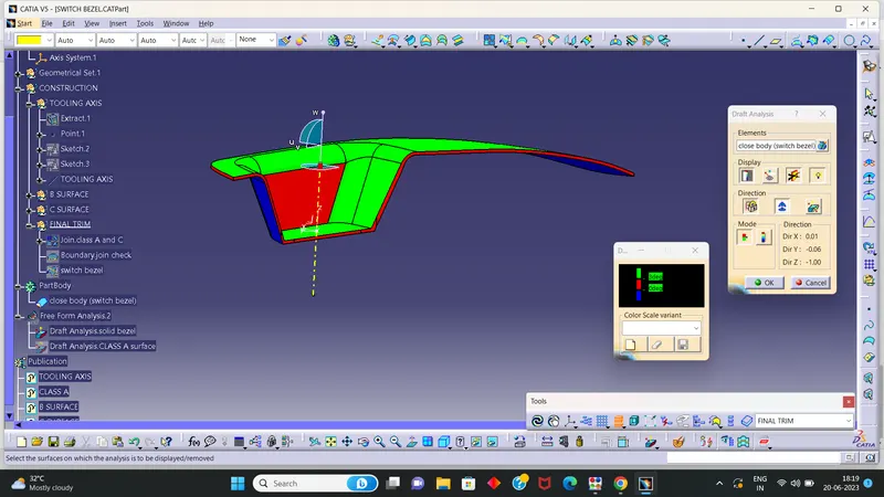
this may be due to the slight deviation occured in the guide curves when smoothing the curve,so adjusting it to a value of 2.9 degrees c surface turns into green.
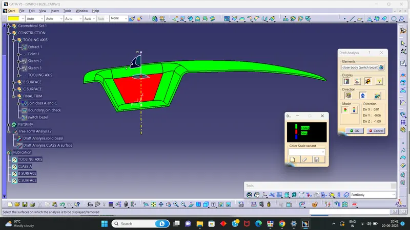
increasing the angle of inclination of tooling axis on XZ plane the draft angle of the wall increases turns into green.
when increasing the value of angle,may leads to an update error,in that case class A surface needs to be extrapolated to a minute value.
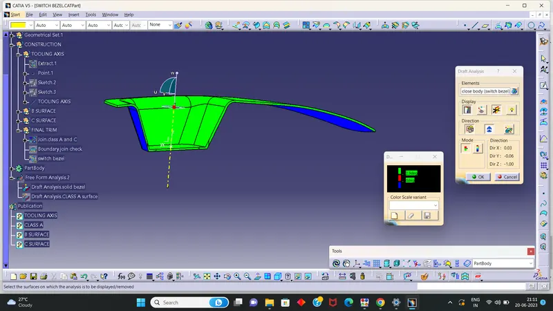
DIFFERENT VIEWS OF DRAFT ANGLE ANALYSIS OF SOLID MODEL
1.
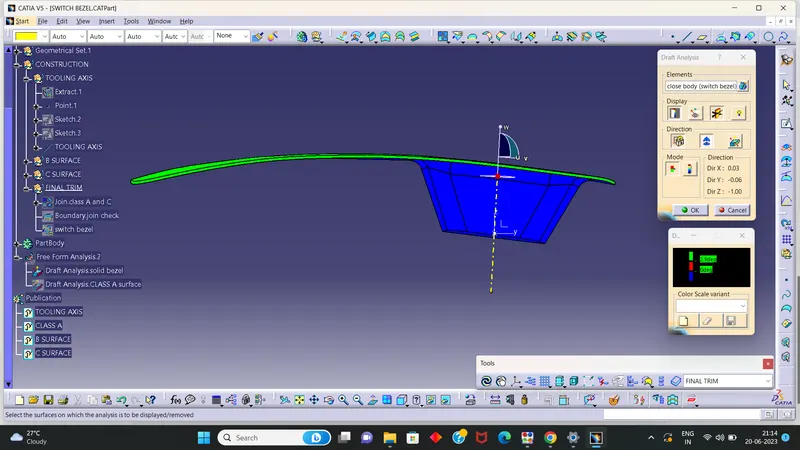
2.
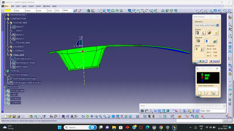
3.
4.