Final Project: Design of an Electric Vehicle
AIM: To Create a MATLAB model of electric car which uses a battery and a DC motor. Choose suitable blocks from Powertrain block set. Prepare a report about your model including following:
Objectives:
1. System level configurations
2. Model parameters
3. Results
4. Conclusion
Theory on electrical Vehicle:
An EV is a shortened acronym for an electric vehicle. EVs are vehicles that are either partially or fully powered on electric power.
Electric vehicles have low running costs as they have less moving parts for maintaining and also very environmentally friendly as they use little or no fossil fuels (petrol or diesel). While some EVs used lead acid or nickel metal hydride batteries, the standard for modern battery electric vehicles is now considered to be lithium ion batteries as they have a greater longevity and are excellent at retaining energy, with a self discharge rate of just 5% per month. Despite this improved efficiency, there are still challenges with these batteries as they can experience thermal runaway, which have, for example, caused fires or explosions in the Tesla model S, although efforts have been made to improve the safety of these batteries.
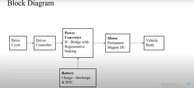
There are two main types of electric vehicles (EV); fully electric and plug-in hybrids:
Battery Electric Vehicles (BEV)
Compared to an internal combustion engine, battery powered electric vehicles have approximately 99% fewer moving parts that need maintenance.
Advantages of a BEV:
- Creates very little noise
- No exhaust, spark plugs, clutch or gears
- Doesn't burn fossil fuels, instead uses rechargeable batteries
BEVs can be charged at home overnight, providing enough range for average journeys. However, longer journeys or those that require a lot of hill climbs may mean that the fuel cells require charging before you reach your destination, although regenerative braking or driving downhill can help mitigate against this by charging the battery packs.
The typical charging time for an electric car can range from 30 minutes and up to more than 12 hours. This all depends on the speed of the charging station and the size of the battery.
In the real world, range is one of the biggest concerns for electric vehicles, but is something that is being addressed by industry.
Plug-in Hybrid Electric Vehicles (PHEV)
Rather than relying solely on an electric motor, hybrid electric vehicles offer a mixture of battery and petrol (or diesel) power. This makes them better for travelling long distances as you can switch to traditional fuels rather than having to find charge points to top up the battery.
Of course, the same disadvantages that apply to combustion engine vehicles also apply to PHEVs, such as the need for more maintenance, engine noise, emissions and the cost of petrol. PHEVs also have smaller battery packs, which means a reduced range.
TWI has been instrumental in the development of electric vehicles, assisting with light-weighting of the vehicles themselves, helping with joining and welding, mitigating against battery combustion and more.
Objective 1:
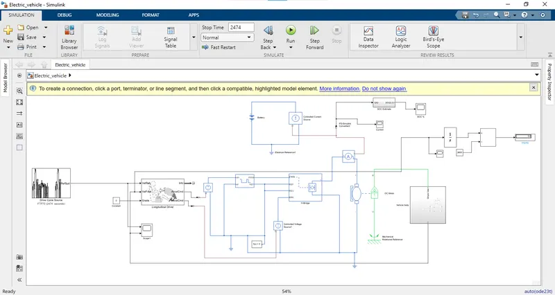
The above figure shows the model of Electric Vehicle using MATLAB and Simulink. All the speeds units in this model are in m/s.
The blocks that were used in this model are
First we have started modelling from the wheels of the vehicle
Here we can observe that we used Tyre of (magic formula type) simple gear box thus we created a base to the electical vehicle.
Firstly we must connect all the tire blocks and created four tyres and by double clicking on the block we get the box with the tyre parameters
Tyre block parameters picture:
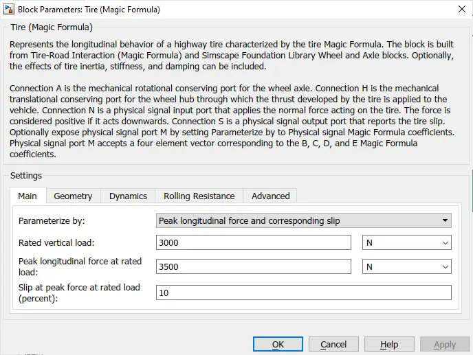
Here we can obsereve that there are various parameters where we can edit according to our requriment. Here we used defaults values for every tire block.
Then the "A" port of the all tyres that is Axle port should be connected with each other ie fornt Axel to front and rea Axel to Rear
In the say way "H" ports are also connected with each other where as H port represents "HUB" of the Vehicle.
Then the remaining ports like "N" and "S" represents the norrmal force and slip of the tire respectively So, normal force on the rear wheels same so "N" port of the both rear wheel block is connected with each other and similarly for the front wheels normal force Slip "S" port represents the slip occuring in the wheel. This port can be connected or left as it is.
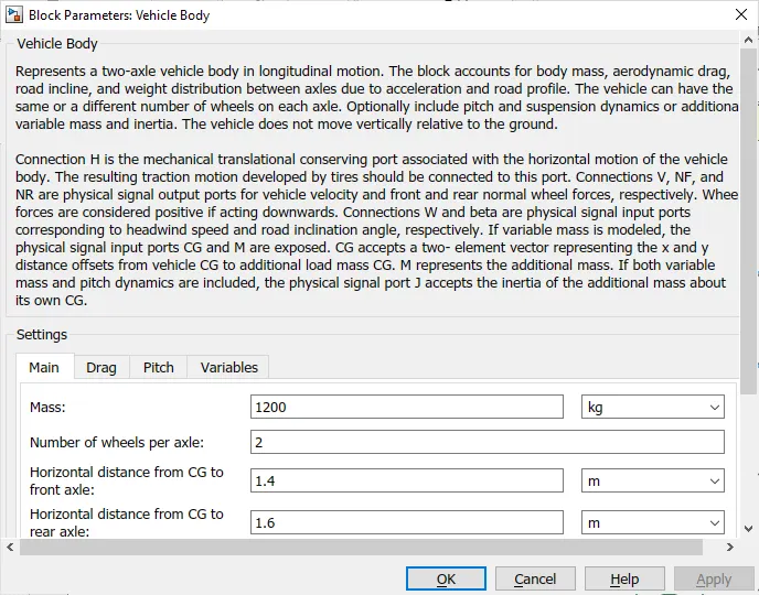
Then we have to use a "Vehicle body block" where it represents the vehicle dynamics. if we double on the block we can observe that various parameters which can be changed according tp our requriment we have used default values of this block in our project
Here ports "NR" and "NF" represent the normal force on the rear tires and the front tires respectively. So, the N port of the rear and front tires are connected with "NR" and "NF" ports accordingly.
Now "H" of the tyre side is connected to "H" of the vehicle body that is HUB of the vehicle.
Then the port "W" and Beta reprents the wind speed and road inclination angle which can be entered as the input in the above model we have not assigned any values as we have just modelled simple electric vehicle with simple calculation assuming it is running on the flat road.
The final port "V" represents the velocity output from the vehicle. So, this connected to the out port then since the power from motor has to transmit to the wheels we have used a transmission block i.e gear box this bllock is connected to rear wheel axle since we have consisdered rear wheel drive.
Now all this setup together they can be made as a subsystem where input of this system is the power given to the simple gear block and output is the velocity of the vehicle.
This subsystem is named as a vehicle dynamics and then we have moved for selecting appropriate motor.
We have taken a simple "DC Motor block" in that block we can change the parameters like rated voltage of the motor, rated speed, no load speed according to our needs.
The motor block have 4 ports they are +,-, "C","R" and +and - are connected to the power supply So the C is consedered to be fixed end of the motor so it is connected to the mechanical reference.
Other port i.e R is connected to the vehicle dynamic subsystem input i.e to simple gear block.
Then a controller is need to control the motor according to the needs we need a controller block to control the speed so we use "H bride block". This block hepls controlling drive of the motor in this block the output voltage i.e + and - port of this block is connected to the - and + of the DC motor which acts aas inpput voltage to the motor.
The PWM port is nothing but PWM signal input port here we can give a PWM input to this port then the REF and REV ports are grounded since we dont need any reverse operation. The BRK port is connected to a constant voltage block which accts as a regenrative braking.
When we double click the "H bridge block" we get the following
In this block we have used same as defaultts but we have changeed the output voltage in the bridge parameters to same as the motor rated voltage other wise it leads to circulatory currents.
Then the PWM is connected to the "H bridge" we used controlled PWM voltage. This block helps in creating the PWM signals which generated according to the variable voltages.
By double clicking the PWM block we can change the parameters like the duty cycle qand thus the frequency and simulation mode is kept in average so that when the model is run it takes less time.
The PWM and REF port of this block is connected to the PWM and REF port is the H bridge block -ref portt is grounded since we dont need negative voltage +ref port is connected to the controlled voltage block so that the input voltage is same always.
Then this block is connected to the "longitudnal driver block" which is nothing but it represents the signal given by driver to driving car.
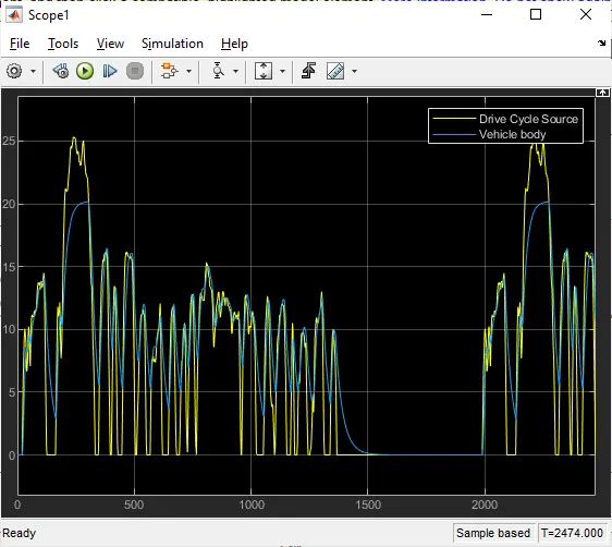
In this block the "VelRef" port is connected to a drive cycle is continuosly compared with the VelFdbl" port where the vehicle speed is given as feedback.
Whenever the vehicle speed is more than the drive cycle speed then the block will otput as deceleration i.e. the "DecelCmd" port which is connected to one port of the "Controlled Voltage port". If the speed of the vehicle is lees than the drive cycle speed the vehicle will accelerate i.e. "AccelCmd" port. Which is again connected to the scope.
The "Longitudnal driver block" is connected to a standard drive cycle using drive cycle block.
For the power source we have used a battery source block which is connecrted to a constant current block when we double click on battery block we get
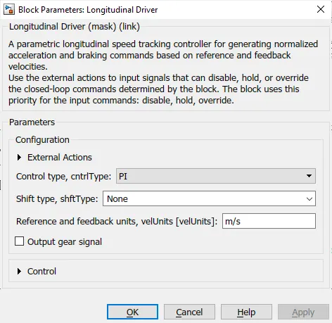
Here we have changed the voltage above to the rated voltage of the DC motor.
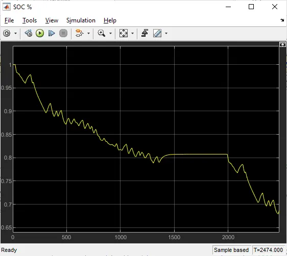
For calculating the SOC of the battery we have used another subsystem in that subsystem we can see that current from the battery is taken as input and connected to the "Rate transition block" where the data is transferred between different rates and task. then "Gain block" is used in order to update the signal coming from the rate transition block at constant gain then it is connected to the discrete time intergrator block where discrete integration of the current signal is done wirth the respect to time.
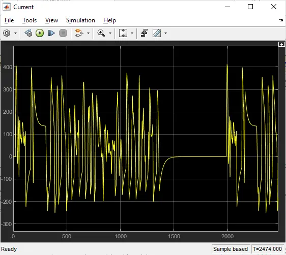
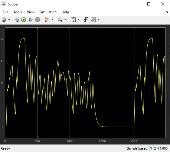
Thus our EV model is completed and once we run the program we get the following results.
SOC Graph:
Current Graph:
Velocity graph:
Vehicle body:
conclusion:
It is clearly visible that the vehicle could be simulated in the same way and in different such simulations could be made to analyze the efficiency of the vehicle by keeping in consideration of various parameters. Therse simulationscould be carried out before deciding the over all specifications that the vehicle should achive in this manner the motor, battery and other components could be chosen and then the actual model could be manfactured. There are chances of varation in the results which could obtaonned in comparasion of the actual and MATLAB simulations as actual conditions would vary the results. All components couold be customized as per the test which has to be carried out like the vehicle mass, the vehicle battery specifications. As we analyze in the test carried out above the vehicle has successfully achived the speed of 25m/s and the vehicle covered a distance of 0.6 kms and if we change the parameters that will be a different case.