Final Project: Design of an Electric Vehicle
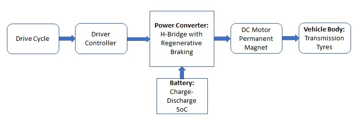
Ans: To model the Electric Vehicle, we must first understand the different significant systems/parts of it. Unlike traditional vehicle, EV requires battery pack and motor with controller for its traction drive in place of Engine.
The major components of EV to be used for its MATLAB modelling are as follows
a) Battery, b) Power Converter, c) Motor d) Motor Controller, e) Transmission(Gear and Tyres) f) Longitudinal Driver
The basic block diagram to understand the model of EV architecture is shown below
System Level Configurations and Model Parameters
1.) Vehicle Body Subsystems: This includes tyres, transmission gear and vehicle body(chassis).
a) Tyre Modelling: The parameters are assumed and set as follows
The tires are parameterized by Peak longitudinal force and corresponding slip. The other block parameters such as - rated vertical load, peak longitudinal force at rated load and slip - are kept default values. The tyre radius is selected as 0.3 m. Also, the rolling resistance is selected with a coefficient of 0.015 as default.
Tyres connection are made as per Front wheel drive and is configured accordingly with vehicle body.
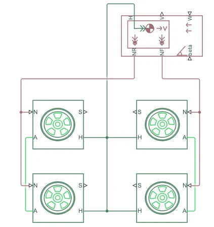
b) Vehicle Body: The default paramenters is taken for this block and connected to the tyres as above
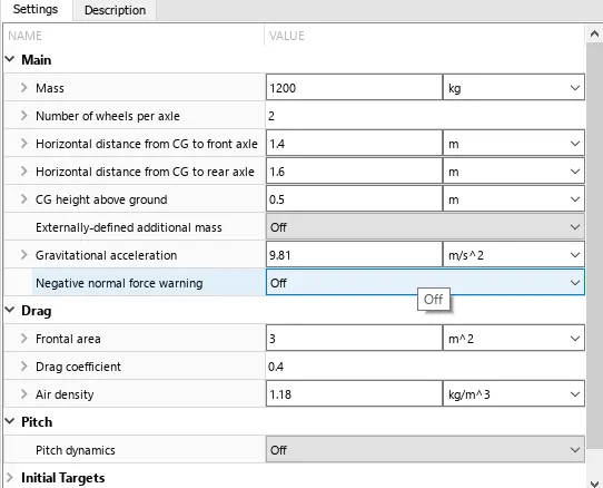
The mass of this vehicle body is 1200kg as default.
c) Transmission/Gear: Simple Gear is taken as transmission box with typical turn ratio of 2. As it is the front wheel drive, the front axle of the tyres are connected to this gear system.
Integrating the above three, the complete Vehicle Body Subsystems is shown below
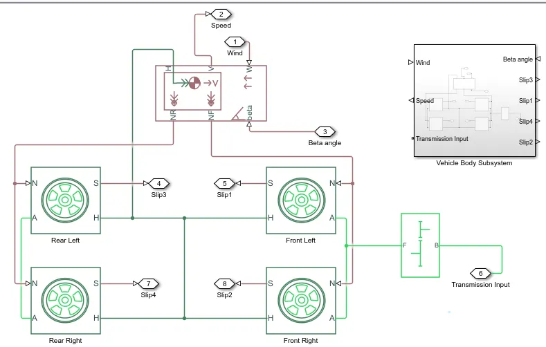
Here the input is Motor output shaft, wind velocity, inclination angle(beta) and the output is final vehicle speed and tyre slips.
2.) DC Motor: Here DC motor is chosen for driving. Some EV uses AC motor also. This is the simple DC motor which converts Electrical power into mechanical power to drive the vehicle. The shaft of the motor(R terminal) is connected to the Gear box input/Transmission input. The casing(C) of the motor is connected to mechanical rotational reference block.
Note : Here, the blue block corresponds to the electrical parts and the green corresponds to the mechanical side. The motor field type is kept as Permanent magnet and the model parameterization is done by rated load and speed. Default values are taken for the armature inductance and the mechanical parameters. All the other parameters are changed as shown below -
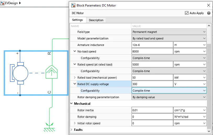
The parameters are choosen as 300V DC, 50kW, 5000rpm rated and 8000rpm no load speed.
3) Motor Controller:
a) H-bridge is used as typical motor controller with inbuilt DC source.
It is modelled as follows with the required pramaters for this drive
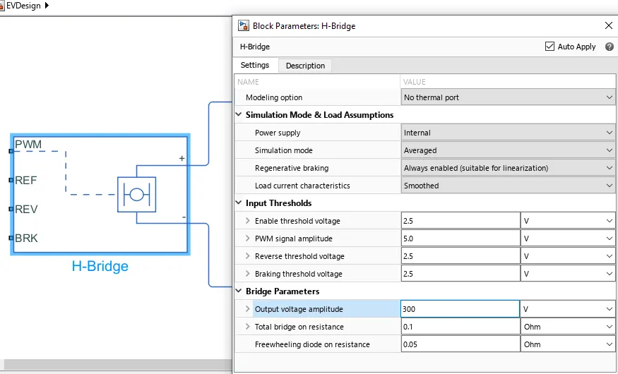
Here, internal power supply option is selected such that no external battery is required as DC source to this H Bridge. Smoothed type of simulation mode is taken for faster simulation time.
b) Controlled PWM voltage block This block provides the required PWM pulse to the H Bridge for generating different voltage to control the motor speed. It is configured as follows
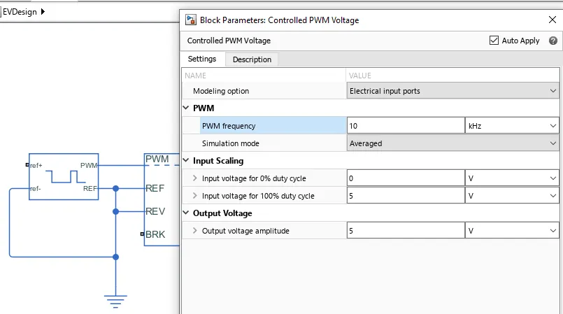
Here, the PWM frequency is taken as 10kHz.
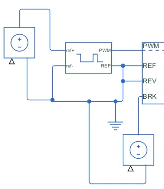
c) Controlled Voltage source This block provides the required voltage for the PWM control and Brake control of the vehicle. It is connected as shown
4) Longitudinal Driver It is a parametric longitudinal speed tracking controller for generating normalized acceleration and braking commands based on reference and feedback velocities. It is based on PI controller. The default parameters are choosen as below for this controller. This block takes the input from Drive cycle speed and actual vehicle speed for the comparison and then the required acceleration and brake command is generated.
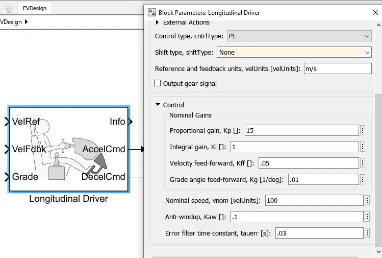
Note: Grade is selected 0.
5. Drive Cycle Ref: Standard available FTP75 drive cycle ref is selected.
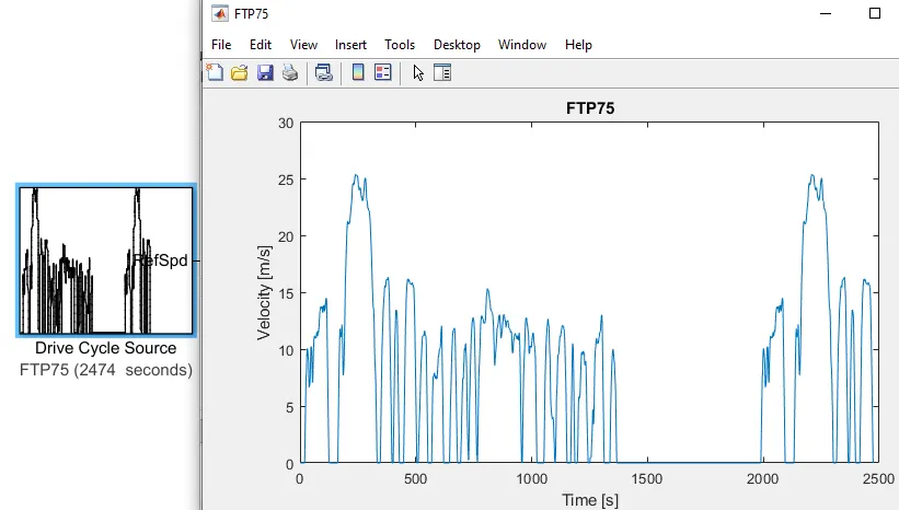
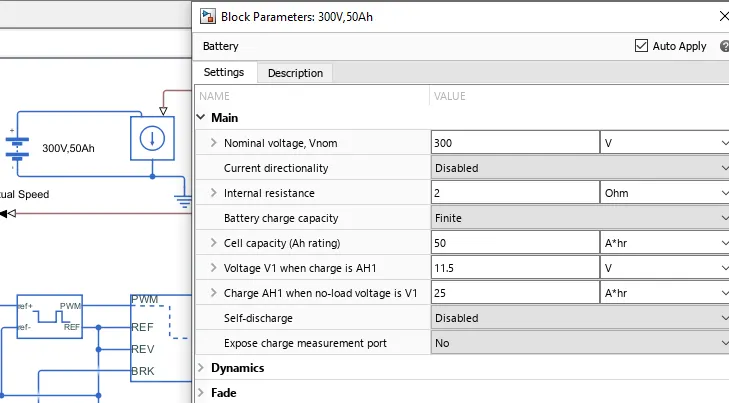
6. Battery: 50Ah battery is connected seperately for SoC calculation.
7. SoC Estimation: SoC is estimated by integrating the current into charge and then dividing by 3600 to convert into Ah consumed. It is then subtracted from Battery full Soc to find the present SoC. Model is shown as below
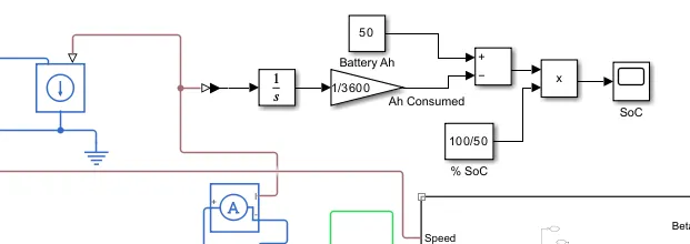
The Complete Vehicle Model is shown below and is also attached:
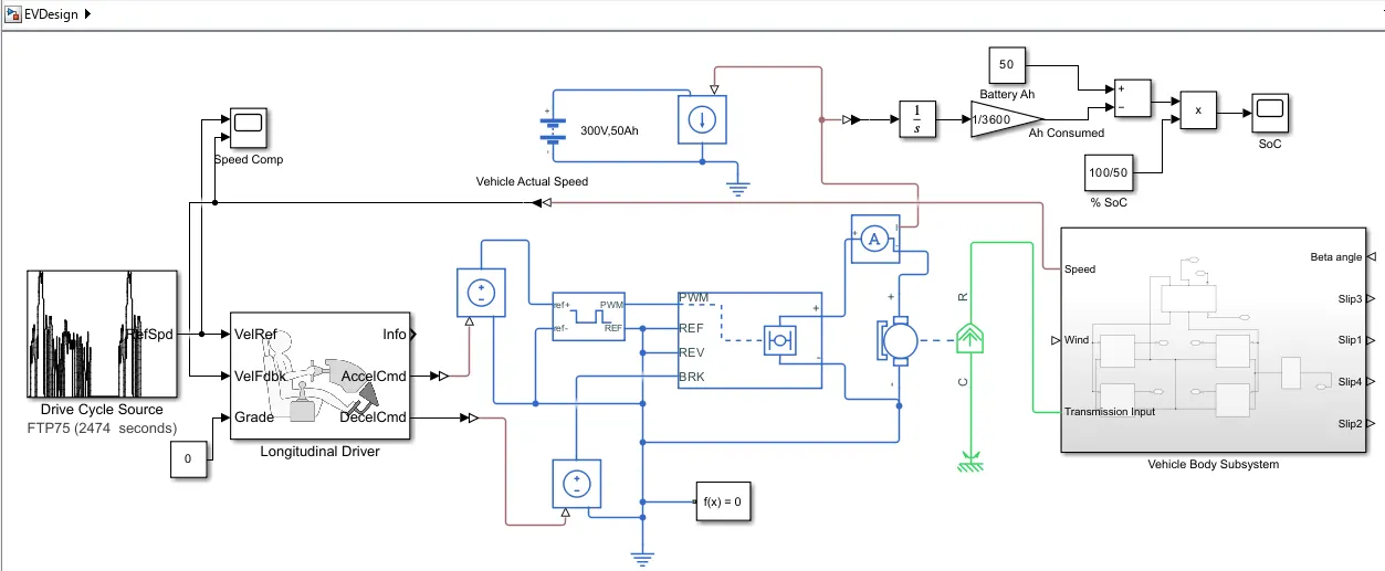
Result/Output: The simulink model runtime is kept 2474s which is the total time for which the input drive cycle ref is defined.
1.) Output Speed:
The vehicle speed almost follows the driving cycle reference. Acceleration pick up is more effective than the braking response. Regenerative braking model is not that effective.
2.) Battery SoC:
Battery is discharged to final 15% SoC at the end of Drive Cycle. There is some charging is also observed which is due to the regenereative braking.
Conclusion:
The Simulink model is created using the DC motor to drive the Front Wheel vehicle. Standard FTP75 drive cycle is taken for reference. The results are found satisfactorily matching the expectations. The results have been properly analyzed.
Additionally, the SOC of the battery is also estimated with the customized blocks. This helps to understand the total runtime or distance that can be covered by the Electric Vehicle.