Final Project: Design of an Electric Vehicle
Create a MATLAB model of electric car which uses a battery and a DC motor. Choose suitable blocks from Powertrain block set. Prepare a report about your model including following:
Objectives:
1. System level configurations
2. Model parameters
3. Results
4. Conclusion
Aim :- To create Electric Vehicle using Matlab and Simulink.
Software : Matlab
Specification : Required body to form a electric vehicle
- vehicle body (Chassis with Wheels connected )
- battery set (BMS)
- motor (permannet magnet DC)
- Controller
- Power Converter(h bridge with regenerative braking)
Objectives:
- To make a most simple and low run time vehicle model using individual components models.
- To check the performance : Speed, SOC,Current etc with the various drive cycles.
- To play with : Motor power, Vehicle body (rlling resistance,Air drag,Weight) inpuuts .
- To know model model and their configuration to match wit the actual speed.
Block diagram
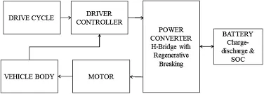
Lets do it in a Matlab window :-
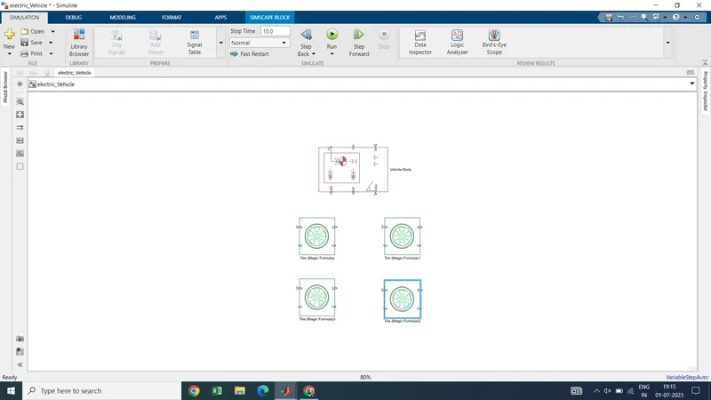
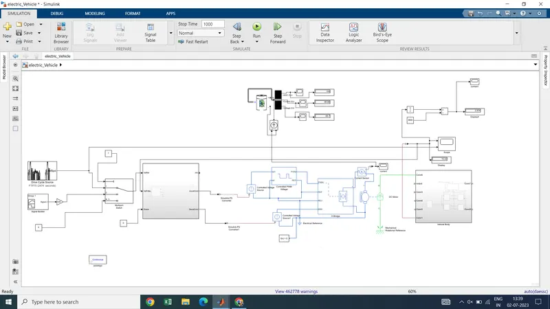
- Here we can see that we have taken vehicle body and tires (magic formula).
- Tires having named as H- Hub; A- Axle; S-tire slip; N- Normal force.
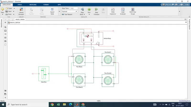
- Now we are going to connect the vehicle body to the tires
- Define rear and front axle tires in the system.
- connect to the vehicle body as Hub to Hub (H-H);A-A(for front and rear axle of tire);
- connect Nr(vehicle ) to the rear axle and NF to the front axle as shown below.
- Connect gear box to the axle (rear)
- We can input to the vehicle body as wind velocity, delta (angle inclination(theta)),Acceleration
Now create a subsystem and name it as Vehicle Body.
- now we need a motor (simple dc motor) Blue one (electrical part),green one (mechanical part)
- connect the motor shaft to gear box as shown
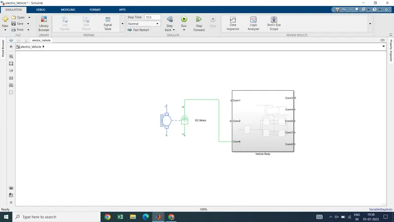
- casing or fixed part of the motor connected to rotational reference frame.
- Now if we directly connect the motor to the converter we loose control over it . it will run at high speed without controller which is not feasible to case.
- Thats why we are connecting controller over here (h bridge)
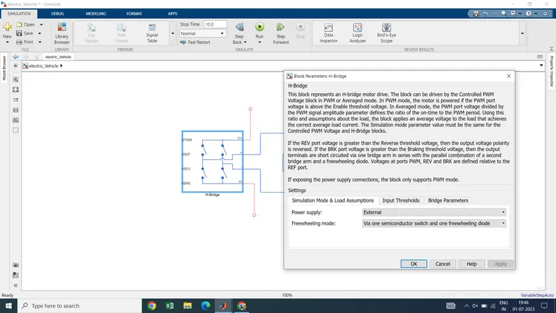
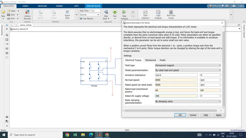
- Set input parameters of the DC motor
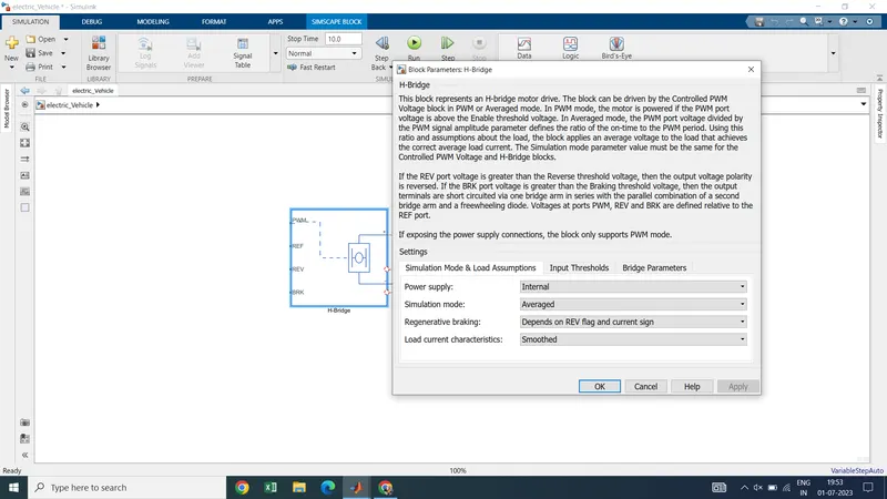
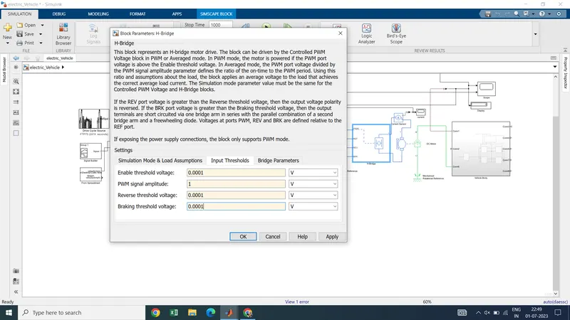
- Set the H bridge to internal ;Simulation type - Averaged and Simulation characteristics as smoothed.
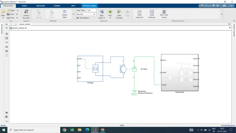
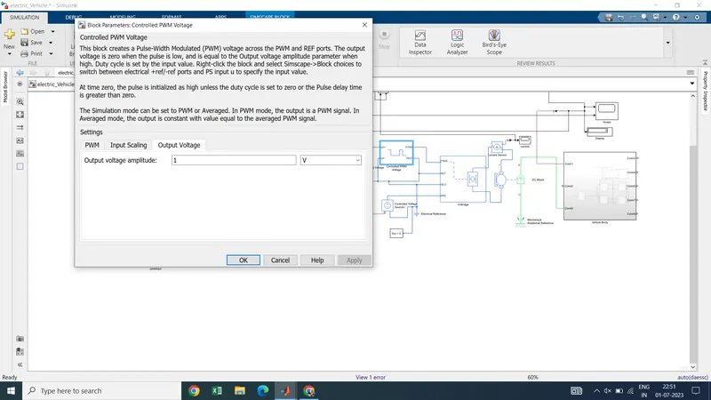
- Now take controlled PWM voltage block to set up a voltage value according to reuirement and can obtained the output as required.
- reference part connected to the electrical reference .
- Now we need controlled voltage source from simcape library to give output to pwm block.
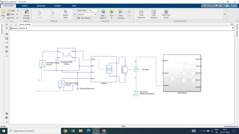
- connect two controlled voltage source to the vehicle part as well as the brake part for regenerative braking and its negative then connected to the electrical reference.
- we can give input to the vehicle using drive cycle using "Drive Cycle Source"
- Take drive cycle source as reference input to the vehicle (Speed vs time).
- We can use our own drive cycle using "signal builder" block
- We can create own drive cycle as the input to the vehicle other than drive cycle.
- Another source can be our spreadsheet (1st column time 2nd column velocity.)
- For multiple option we need multiple input block to connect multiple input to the vehicle (drive cycle)
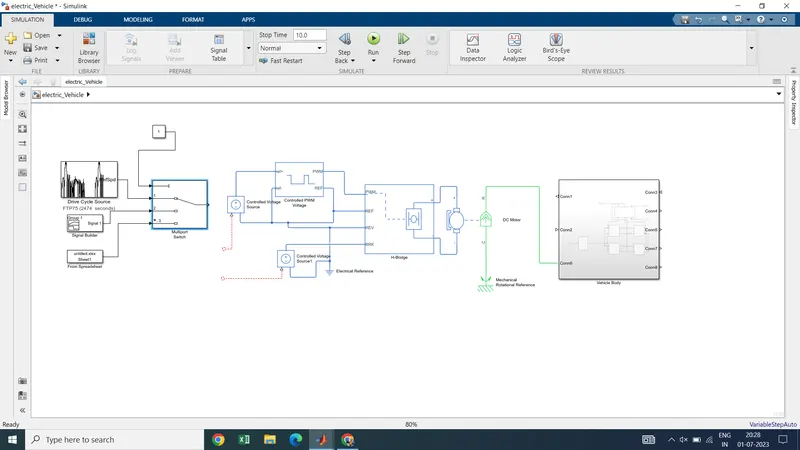
- From constant block we can select which input we are going to give to the vehicle .
- for example if we write 1 in the constant block it will select drive cycle as input and so on .
- Now we want to convert acceleration and deceleration command for that we need controller
- Take longitudanal driver which is looking at the input command as shown.
- connect to the input signal as a drive cycle .
- connect reference speed (vehicle feedback ) to the vehicle and connect scopw there as well.
- connect current source to the motor and conncet one scope there with the help of ps to simulink converter.
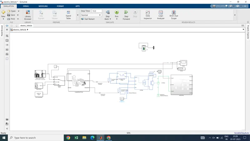
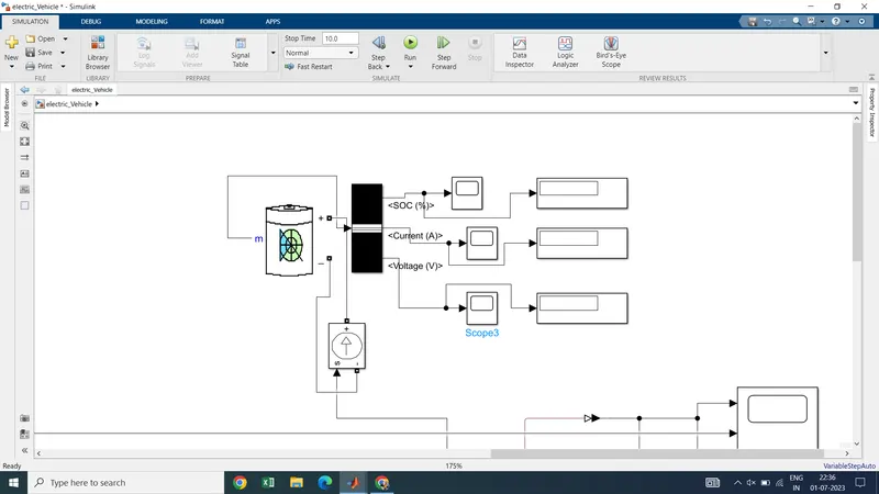
- Now take lithium ion battery to estimate the state of charge .
- connect it with the bus selector and take out output as SOc, current and voltage.
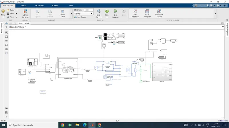
After connection whole model looks like :-
Simulation :-
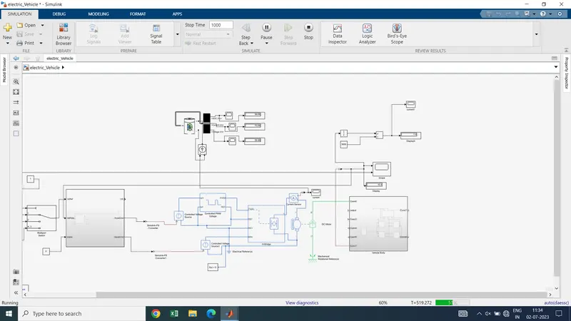
we have started simulation of 1000 sec .
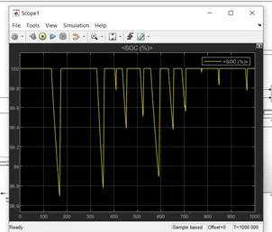
Here we can see that as vehicle start running the battery start discharges .
after simulation
Scope shows the battery percentages as bettery discharges to some extend and again recharge as well charges with the regenerative braking.
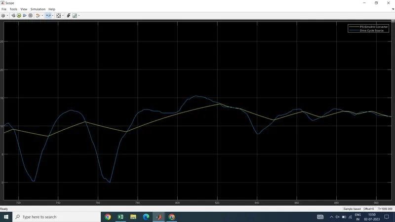
here the actual drive cycle and drive cycle source is trying to reach the output of the vehicle via given driving input.
Conclusion and Comments :- In this way the project is completed.
- Power rating of DC motor and max. vehicle speed
- PI control loop signal for tracking reference speed
- battery discharge and km per full charge
- Regerative braking effects
- various model library (simscape,simulink )categories.
- Simulation time and drive cycle time .