Final Project: Design of an Electric Vehicle
Final Project: Design of an Electric Vehicle
Objective:
Lets design and model an electric power train for Tata Tigor EV.
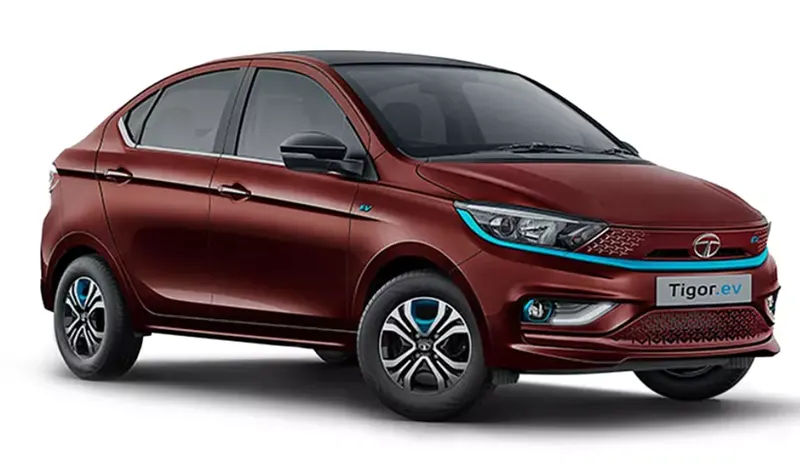
Vehicle specifications required for our modelling:
|
Sl.No |
Parameter |
Value |
|
1 |
Kerb weight |
1235 Kg |
|
2 |
Length*breadth*height |
4m*1.7m*1.5m |
|
3 |
Top speed |
120kmph |
|
4 |
Acceleration (0-100kmph) |
12.63seconds |
|
5 |
Tyre dimension |
175/65 R14 |
|
6 |
Maximum restart gradeability |
29% |
|
7 |
Range per charge |
300km |
Assumptions:
|
Sl.No |
Parameter |
Value |
|
1 |
airdensity(ρ) kg/m3 |
1.225 |
|
2 |
aerodynamic drag coefficient (Cd) |
0.28 |
|
3 |
Rolling resistance coefficient (μrr) |
0.02 |
|
4 |
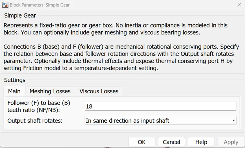
Gear ratio |
18 |
|
5 |
Gear efficiency |
0.9 |
Vehicle dynamics
Force calculations:
Max total tractive force required, Ftrac = Acceleration force(Fa)+Aerodynamic drag force(Fd)+Rolling resistance force(Fr)+Grade force(Fg)
Acceleration force(Fa)
= Total vehicle mass * acceleration
= (kerb weight + passenger weight + luggage) * acceleration
= (1235+(70*5)+200)kg * 2.2 m/s2
= 3927N
Aerodynamic drag force(Fd)
= 0.5* airdensity(ρ) *aerodynamic drag coefficient (Cd) * vehicle frontal area (A) * velocity2(V2 )
= 0.5 * 1.225kg/m3 * 0.28 * 2.6m2 * 33.332 m/s
= 495.3N
Rolling resistance force(Fr)
= Rolling resistance coefficient (μrr) * Total vehicle mass(m) * acceleration due to gravity(g)
= 0.02 * 1785kg * 9.8m/s2
= 350N
Grade force(Fg)
= Total vehicle mass(m) * acceleration due to gravity(g) * sin(angle of max gradeability in degrees)
= 1785kg * 9.8m/s2 * sin(tan-1(29/100))
= 4872.23N
Hence The total tractive force, Ftrac = Fa+Fd+Fr+Fg = 3927+495.3+350+4872.23 = 9644.5N
Power calculations( at extreme limits) :
Max Acceleration power = Fa*V = 3927 * 33.33 = 130KW
Max Power to over come air drag = Fd * V = 495.3 * 33.33 = 16.5KW
Max power to over come rolling resistance = Fr * V = 350 * 33.33 = 11.6KW
Max power for hill climbing(at speed 10 m/s ) = Fg * V = 4872.23 * 10 = 48.7KW
Hence The total tractive power, Ptrac = 206.8 KW
Motor selection
Maximum Torque to be developed by the motor to meet the maximum tractive force is
Tmax = (Total Ftrac * wheel radius) / (Gear ratio * Gear efficiency)
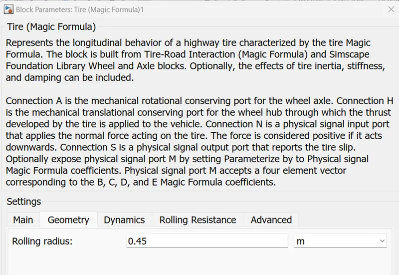
Wheel radius, r = (0.65*175mm) + 14 inches = 0.45 meters
Tmax = (9644.5*0.45)/(18*0.9) = 268Nm
Angular speed, ω = Pout/Tout = Ptrac/T = 206800/268 = 772 rad/sec = 772 * 9.55 = 7370 RPM
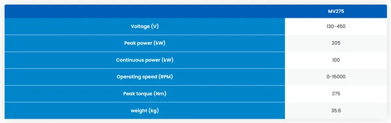
Therefore we will have to choose a motor which can deliver a peak power of 207kw and peak torque of 268Nm.
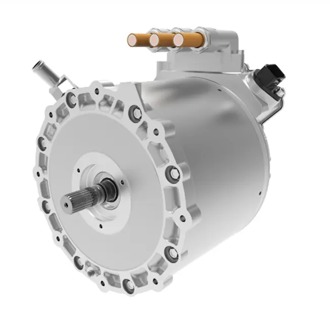
Lets select below motor from the IPM MV275 series, manufactured by Dana TM4:
MV275 Internal Permanent Magnet Motor
Battery design
The analysis and calculations for battery pack design is made with the help of excel as below:
|
ASSUMPTIONS |
|
|
Energy Consumption [Wh/km] |
270 |
|
4 - wheeler range [km] |
300 |
|
Battery DoD |
85% |
|
Battery voltage [V] |
380 |
|
Battery total energy [Wh] |
95294.1176 |
|
Battery capacity [Ah] |
250.773994 |
We have considered below 7 types of cells from different manufactures to analyse and find the best suited cell for our battery pack.
|
TYPE OF Li-ion CELLS CONSIDERED |
|||||||
|
Manufacturer |
Panasonic |
A123-Systems |
Molicel |
A123-Systems |
Toshiba |
Kokam |
Kokam |
|
Type |
cylindrical |
cylindrical |
cylindrical |
pouch |
Pouch |
pouch |
pouch |
|
Model |
NCR18650B |
ANR26650m1-B |
ICR-18650K |
20Ah |
20Ah |
SLPB78216216H |
SLPB7570270 |
|
Source |
[4] |
[5] |
[6] |
[7] |
[8] |
[9] |
[9] |
|
Length [m] |
0.0653 |
0.065 |
0.0652 |
0 |
0 |
0 |
0 |
|
Diameter [m] |
0.0185 |
0.026 |
0.0186 |
0 |
0 |
0 |
0 |
|
Height [m] |
0 |
0 |
0 |
0.227 |
0.103 |
0.272 |
0.272 |
|
Width [m] |
0 |
0 |
0 |
0.16 |
0.115 |
0.082 |
0.082 |
|
Thickness [m] |
0 |
0 |
0 |
0.00725 |
0.022 |
0.0077 |
0.0077 |
|
Mass [kg] |
0.0485 |
0.076 |
0.05 |
0.496 |
0.51 |
0.317 |
0.317 |
|
Capacity [Ah] |
3.2 |
2.5 |
2.6 |
19.5 |
20 |
31 |
15.6 |
|
Voltage [V] |
3.6 |
3.3 |
3.7 |
3.3 |
2.3 |
3.7 |
3.6 |
|
C-rate (cont.) |
1 |
10 |
1 |
1 |
1 |
2 |
2 |
|
C-rate (peak) |
1 |
24 |
2 |
10 |
1 |
3 |
3 |
|
CELL LEVEL CALCULATIONS |
||||||
|
Manufacturer |
Panasonic |
A123-Systems |
Molicel |
A123-Systems |
Toshiba |
Kokam |
|
Type |
cylindrical |
cylindrical |
cylindrical |
pouch |
pouch |
pouch |
|
Model |
NCR18650B |
ANR26650m1-B |
ICR-18650K |
20Ah |
20Ah |
SLPB7570270 |
|
Energy [Wh] |
11.52 |
8.25 |
9.62 |
64.35 |
46 |
114.7 |
|
Volume [l] |
0.017553 |
0.03451 |
0.017716 |
0.26332 |
0.26059 |
0.171741 |
|
Energy density |
237.53 |
108.55 |
192.4 |
129.74 |
90.2 |
177.16 |
|
gravimetric [Wh/kg] |
||||||
|
Energy density |
656.31 |
239.06 |
543.01 |
244.38 |
176.52 |
327 |
|
volumetric [Wh/l] |
||||||
| BATTERY LEVEL CALCULATIONS | ||||||
| Manufacturer | Panasonic | A123-Systems | Molicel | A123-Systems | Toshiba | Kokam |
| # of cells in string [-] | 106 | 116 | 103 | 116 | 166 | 103 |
| String energy [Wh] | 1221.12 | 957 | 990.86 | 7464.6 | 7636 | 11814.1 |
| # of strings [-] | 79 | 100 | 97 | 13 | 13 | 9 |
| BP energy [kWh] | 96.46848 | 95.7 | 96.11342 | 97.0398 | 99.268 | 106.3269 |
| BP capacity [Ah] | 252.8 | 250 | 252.2 | 253.5 | 260 | 279 |
| # total cells [-] | 8374 | 11600 | 9991 | 1508 | 2158 | 927 |
| BP mass [kg]* | 406.139 | 881.6 | 499.55 | 747.968 | 1100.58 | 293.859 |
| BP volume [l]* | 146.988822 | 400.316 | 177.000556 | 397.08656 | 562.35322 | 159.203907 |
| BP peak current [A] | 252.8 | 6000 | 504.4 | 2535 | 260 | 837 |
| BP peak power [kW] | 96.064 | 2280 | 191.672 | 963.3 | 98.8 | 318.06 |
| BP continuous current [A] | 252.8 | 2500 | 252.2 | 253.5 | 260 | 558 |
| BP continuous power [kW] | 96.064 | 950 | 95.836 | 96.33 | 98.8 | 212.04 |
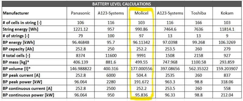
From the above analysis we can conclude that building the pack with Molicel would be the most suited selection for our application.
Hence the battery pack configuration will be: 103S97P
Pack capacity: 95KW or 250Ah
Simulink model
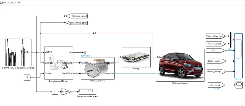
A complete EV vehicle was modelled in simulink using the above calculated parameter configurations as shown below:
Vehicle subsystem:
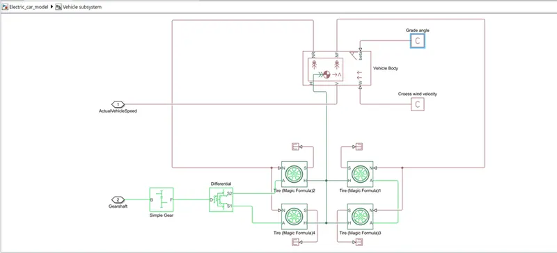
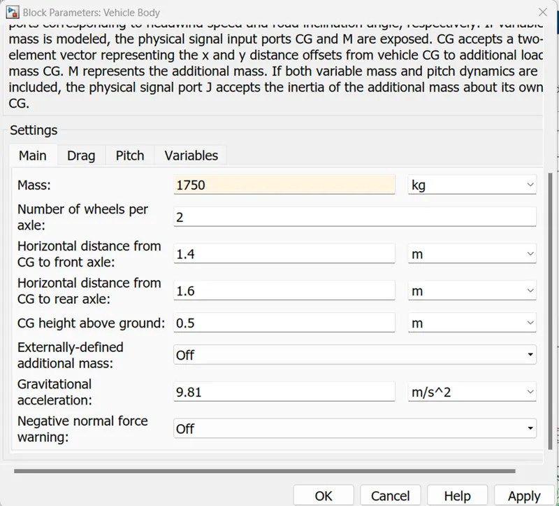
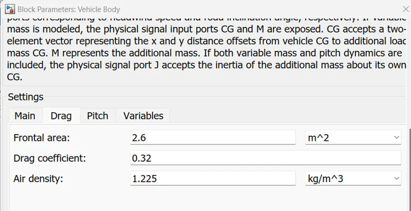
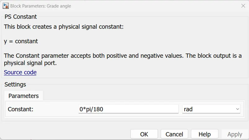
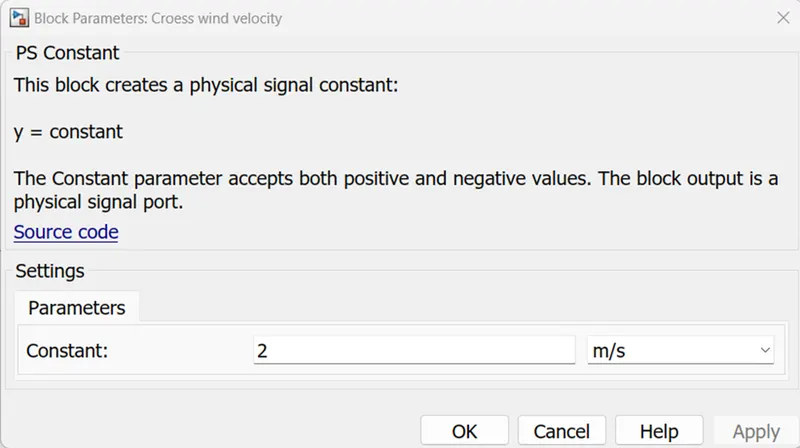
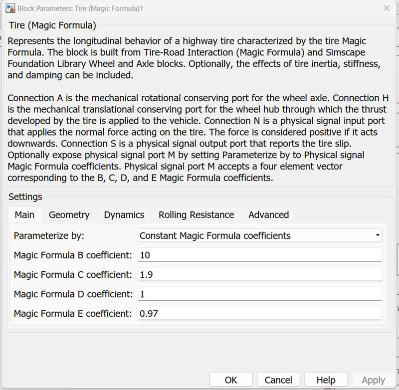
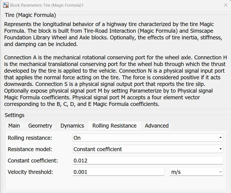
This block implements all the vehicle dynamics related design parameters such as mass, rolling resistance, air drag, grade angle which decides the total tractive force required by the vehicle.
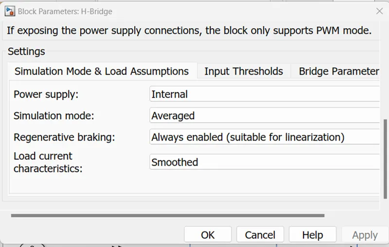
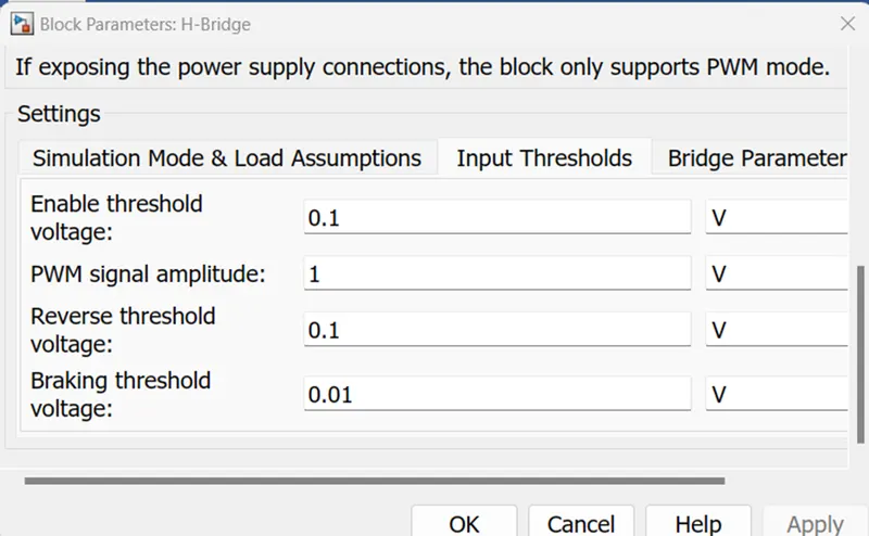
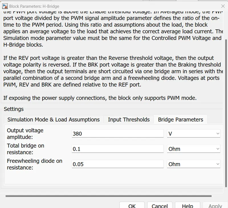
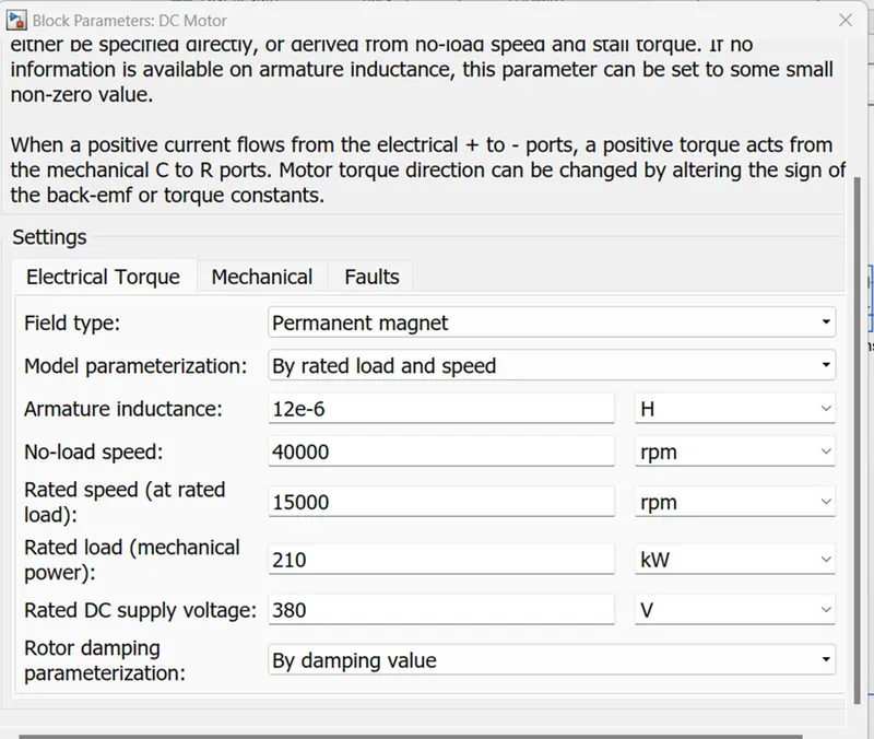
Motor and controller subsystem:
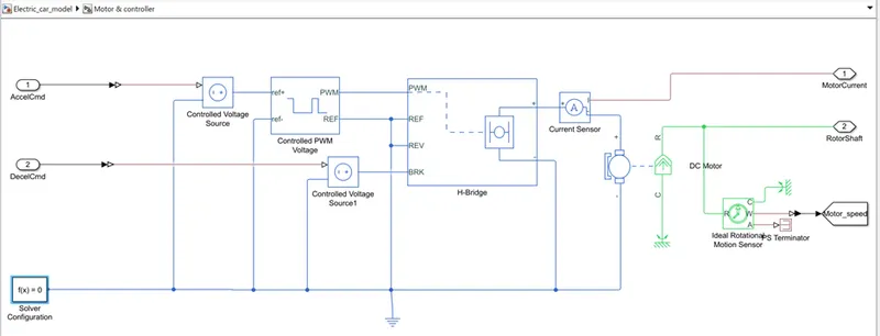
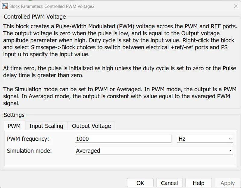
For sake of simplicity here we have chosen a simple DC motor model with above calculated ratings..
Longitudinal driver subsystem:
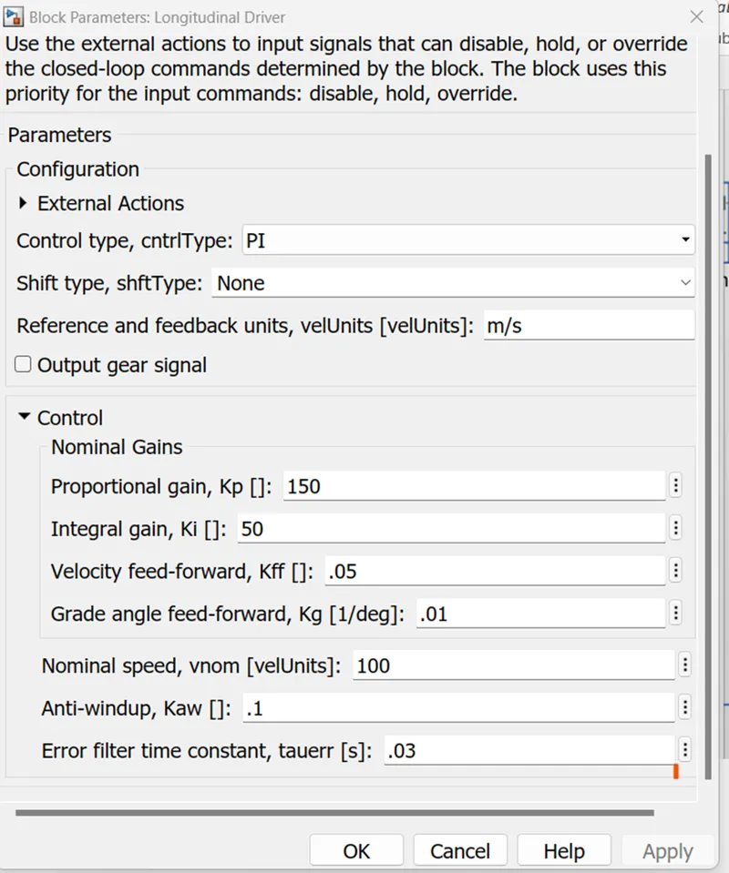
This block will act as a PID controller working in closed loop which compares the feedback actual vehicle speed with the reference speed input and calculate the error and provide the acceleration or decceleration commands accordingly to the motor controller.
Drive cycle source:
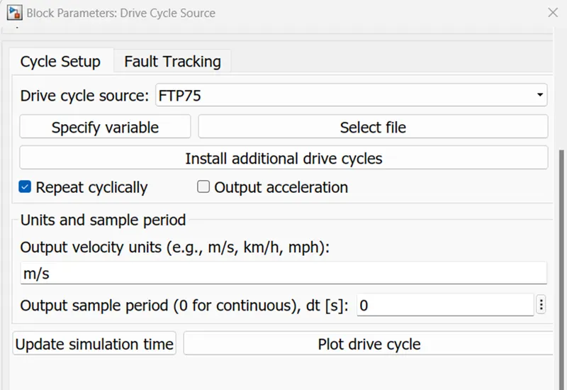
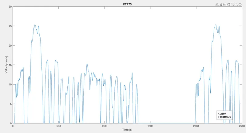
It is a predefined set of data of speed vs time which can be used to analyse the vehicle performance. Here we have used FTP-75 drive cycle which has a total range of 17.7km and total time of 2474 seconds.
Top speed: 25m/s
Average speed: 7.1m/s
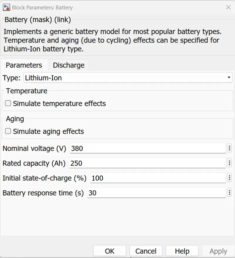
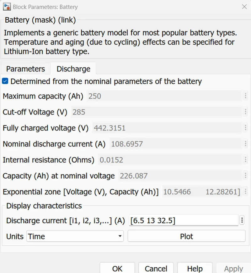
Battery subsystem:
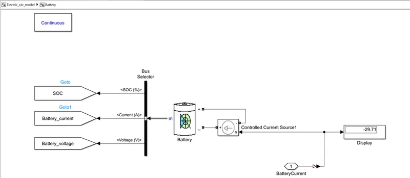
For simplicity here we have chosen a li-ion battery available in Simulink and provided our above calculated ratings. This battery system model is designed to find out the SOC and battery voltage and current characteristics during the drivecycle. Hence we are taking the motor armature current provided by the H-bridge(Power supplied internally) and feeding that current to the battery via a controlled current source. Therefore the battery will get charged or discharged accordingly and we will get the SOC as desired.
Simulation Results & Analysis
- The developed simulink model was simulated for the time period of the FTP-75 drive cycle 2724 seconds to analyse if the vehicle speed is following the reference speed correctly.
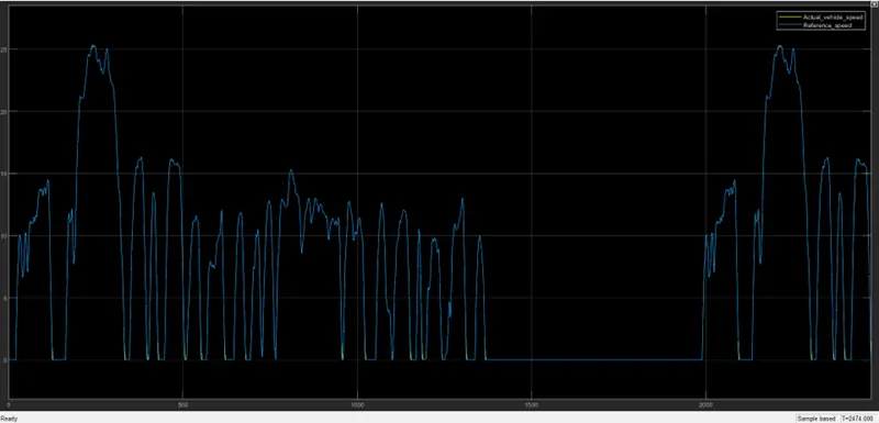
From the result we can conclude that the model is precisely tracking the reference speed..
- The developed simulink model was simulated for a range of 300 km to analyse the battery SOC and mileage of the vehicle.
Considering our drive cycle FTP-75, one drive cycle is for 17.77km
17.77*17 = 302.09 km
Therefore, we have to provide 17 cycles of FTP-15 drive cycles as input
Total execution time = time for one cycle * 17 = 2747seconds * 17 = 46699 seconds
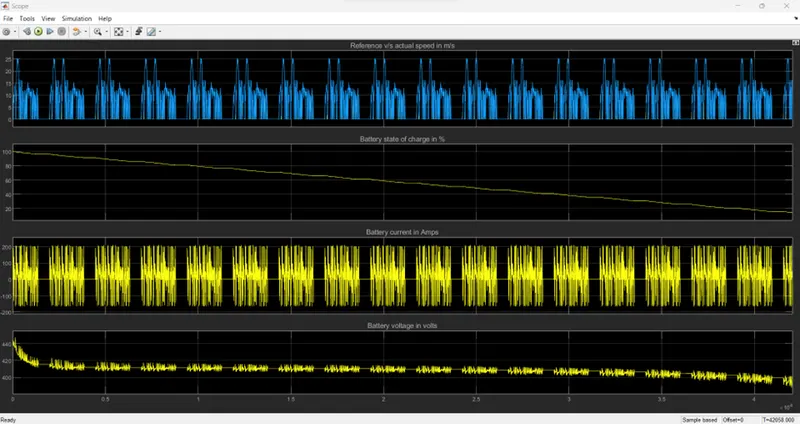
From the result we can see, SOC starting from 100% has dropped to 15% towards the end of the simulation. Also the the battery voltage and current fluctuation is within the desired limits. Hence, we can conclude that the chosen battery capacity 95KWh and motor ratings are adequate to meet the desired traction power and to provide the assumed range of 300Km/charge.
- We have successfully designed and configured a complete EV system and modelled the parameters and implemented in Simulink.