Final Project: Design of an Electric Vehicle
AIM: To design an electric vehicle with a DC motor using MATLAB and SIMULINK.
OBJECTIVE: To understand and implement the following
- System-level configurations
- Model parameters
- Results
- Conclusion
VEHICLE BLOCK DIAGRAM:
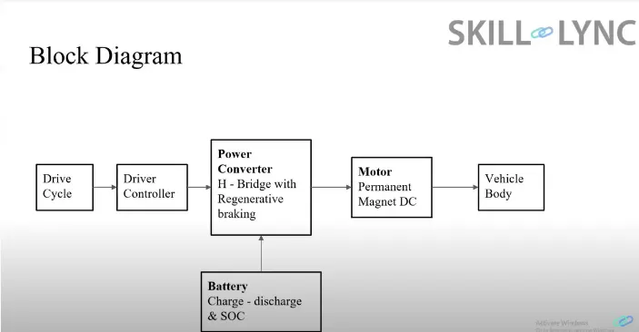
Above is the basic block diagram of an EV, this will be implemented on SIMULINK using a few SIMSCAPE blocks as well.
SIMULINK MODEL
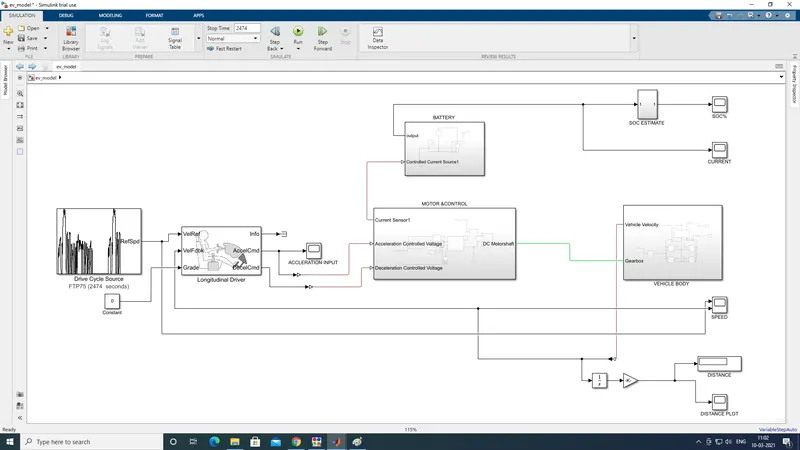
The Simulink model outline is shown above. A detailed explanation of each subsystem is given below.
- Drive cycle source
An FTP75 drive cycle was selected, the image and setup of the block are shown below.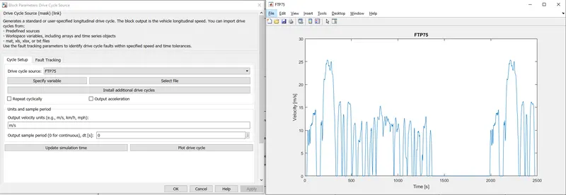
- LONGITUDINAL DRIVER:
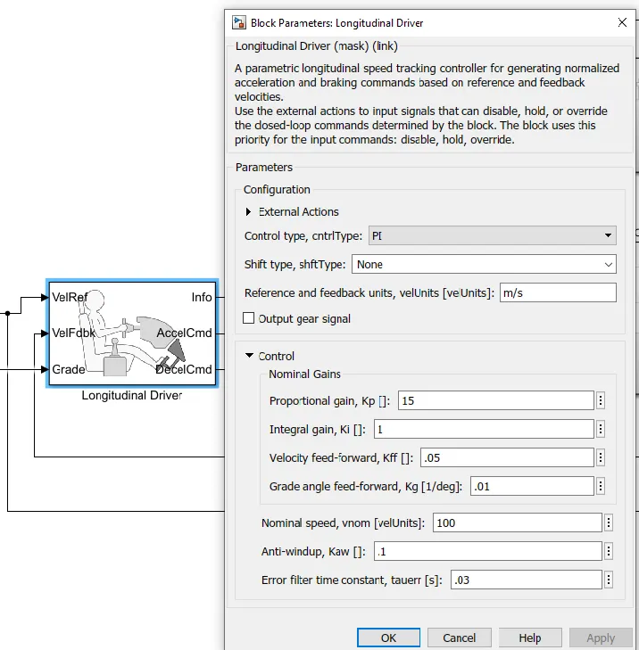
Input Ports:
- VelRef- this takes a reference velocity from the drive cycle source block
- VelFDBK- takes velocity feedback from the vehicle body.
- Grade- this is the grade of the road that the vehicle is driving on.
Output Ports:- accelcmd- acceleration Simulink signal that is converted to PS signal for motor control input.
- decelcmd- deceleration Simulink signal that is converted to PS signal for motor control input.
- MOTOR & CONTROL
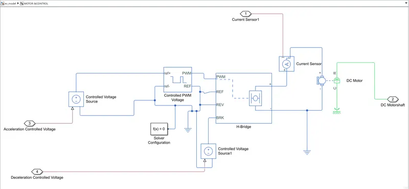
Input Ports:- Acceleration controlled voltage - acceleration PS signal that is connected to the controlled voltage block to give the reference current to the controlled PWM voltage block.
- Deceleration controlled voltage - deceleration PS signal that is connected to the controlled voltage block to give the reference current to the controlled PWM voltage block.
- Dc motorshaft- Mechanical rotation output of the DC motor which connects to the gearbox
- Current sensor output - Output signal that goes to the battery to get the current discharge.
Controlled PWM voltage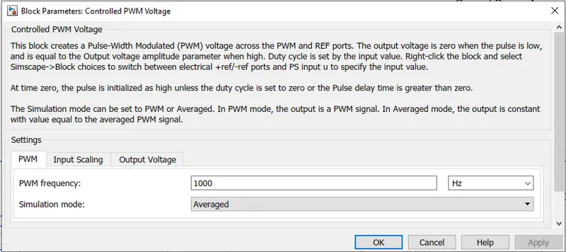
H-Bridge
The H-bridge block, give the output voltage required to run the Dc motor. In this simulation, the power supply is taken as internal for simplicity sake, the output supplied is sensed with the current sensor and that data is given to the battery block to measure the discharge from the battery and hence calculate the SOC.
The H-Bridge output voltage amplitude is generally taken as a value that is rated higher than the battery and motor voltage. this is to combat any effects of current leakage that may prevent the motor from running at the desired voltage and frequency.
The simulation parameters of the H-Bridge is shown below.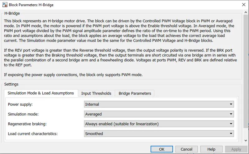
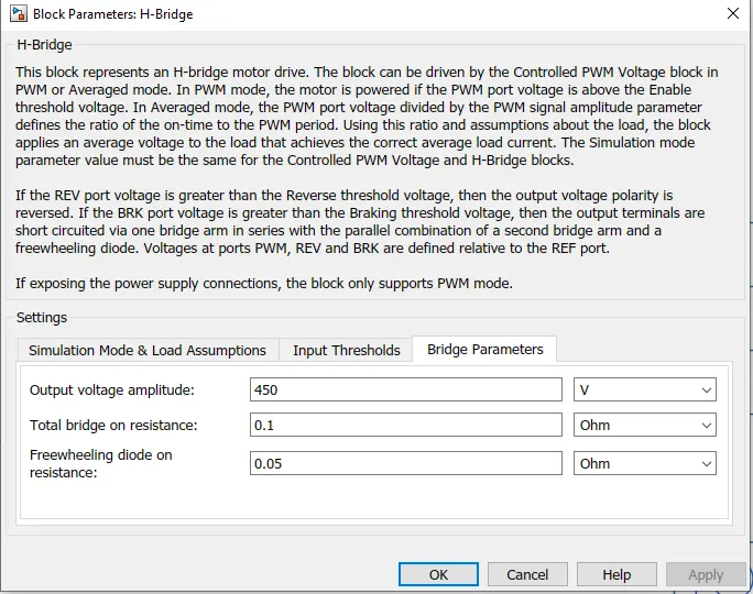
DC motor
The DC motor characteristics are shown below.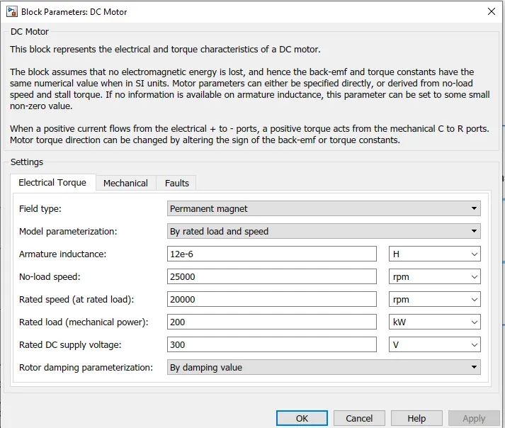
- BATTERY
The contents of the Battery subsystem is shown below: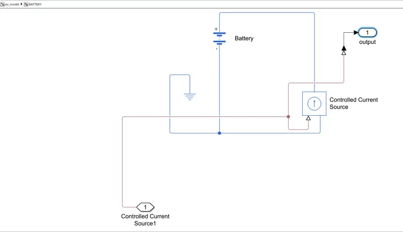
The SOC estimate block is as shown below, This block estimates the Battery state of charge using the output from the battery block using the arrangement of blocks shown below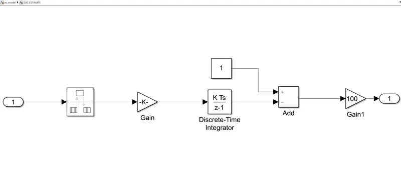
- Vehicle body Subsystem
The vehicle body block consists of the Gearbox, tire and vehicle body blocks. The arrangement of these blocks is shown below.
Input Port:- Gearbox- Takes Mechanical rotational input from the dc motor and is connected to the gearbox.
Output Ports:- Vehicle velocity- The velocity of the vehicle is sent to the longitudinal driver block and to the output scope.
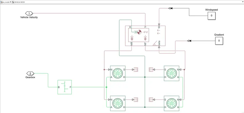
1) Vehicle body: The description of the block is given below: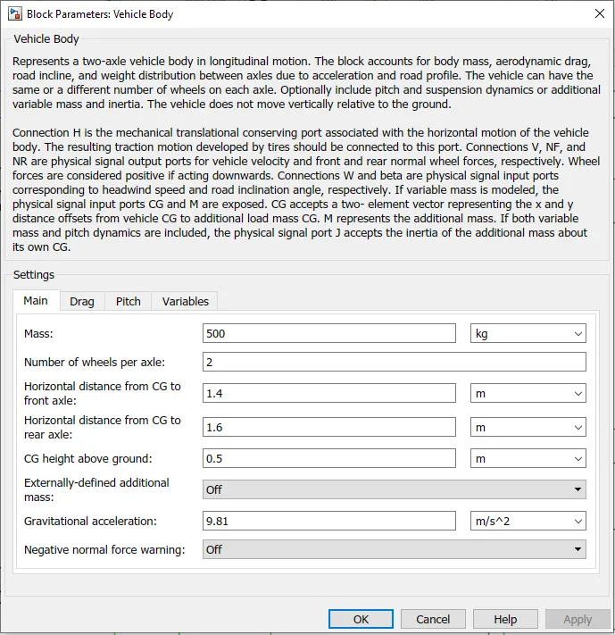
2) Tire block: The tire characteristics are parameterized by peak longitudinal force and corresponding slip. The block description and parameters selected are shown below.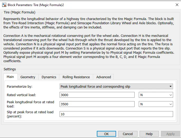
SIMULATION OUTPUT:
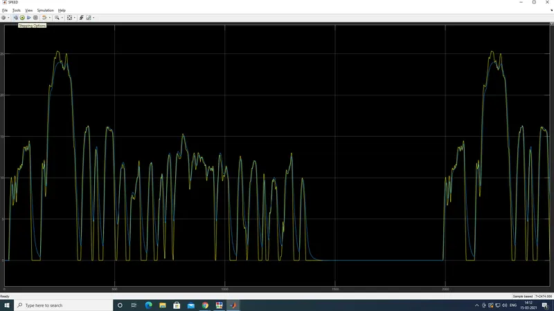
the velocity profile is as shown below. The yellow curve is the drive cycle and the blue curve is the vehicle velocity profile.
The distance curve is shown below. the total distance travelled is 19.28 km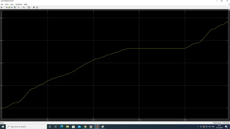
The current output is :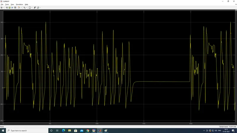
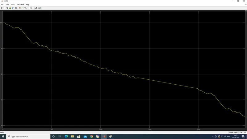
The Battery SOC is shown below
CONCLUSION:
The electric vehicle was modelled successfully!