Design of an Electric Vehicle
PROJECT: DESIGN OF AN ELECTRIC VEHICLE
AIM:
Construct a DC motor and battery-powered electric automobile model in MATLAB. Select the appropriate blocks from the Powertrain block set.
OBJECTIVES:
- Using individual component blocks, create a vehicle model with the lowest run-time possible.
- To do individual car model simulations and incorporate
- Checking performance indicators including speed, battery level, and current
- Provide inputs for the vehicle's body and motor.
- To be familiar with MATLAB models and how to configure them to match actual car
INTRODUCTION OF ELECTRIC VEHICLES:
An electric motor powers an electric vehicle (EV) instead of an internal combustion engine, which produces power by burning a mixture of fuel and gases.
Therefore, in order to solve the issue of increasing pollution, global warming, decreasing natural resources, etc., such a vehicle is considered as a potential substitute for current-generation automobiles.
Although the idea of electric vehicles has been around for a while, it has attracted a lot of attention in the last ten years due to the growing environmental effects of fuel-based vehicles and their increased carbon footprint.
While some electric vehicles (EVs) employed lead-acid or nickel-metal hydride batteries, lithium-ion batteries are generally regarded as the industry standard because of their longer lifespan, high energy retention, and low self-discharge rate of just 5% per month. Although attempts have been made to increase the safety of these batteries, there are still issues with them due to the possibility of thermal runaway, which has, for instance, led to fires or explosions in the Tesla Model S.
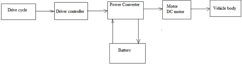
BLOCK DIAGRAM:
Battery Electric Vehicle (BEV)
A battery and an electric drive train power a complete battery electric vehicle (BEV), also known as an all-electric vehicle (AEV). These particular electric vehicles lack an ICE. A sizable battery pack that can hold electricity is charged by connecting to the power grid. The battery pack then fuels one or more electric motors that power the electric vehicle.
Architecture and Main Components:
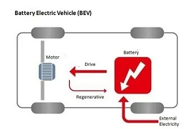
Components of BEV
- Electric motor
- Inverter
- Battery
- Control Module
- Drive train
BEV Operating Principles
For the electric motor, power is transferred from the DC battery to AC.
The controller receives a signal from the accelerator pedal and modifies the frequency of the AC power from the inverter to the motor to change the speed of the vehicle.
Through a cog, the motor is connected to and rotates the wheels.
The motor transforms into an alternator and generates power when the brakes are applied or the electric vehicle is slowing down, sending that power back to the battery.
Examples of BEV:
Volkswagen e-Golf, Tesla Model 3, BMW i3, Chevy Bolt, Chevy Spark, Nissan LEAF, Ford Focus Electric, Hyundai Ioniq, Karma Revera, Kia Soul, Mitsubishi i-MiEV, Tesla X, Toyota Rav4.
Hybrid Electric Vehicle (HEV)
These hybrid vehicles are frequently referred to as parallel hybrids or normal hybrids. HEVs have an ICE in addition to an electric motor. In these sorts of electric vehicles, the motor is powered by batteries instead of the internal combustion engine, which runs on fuel (gasoline and other forms of fuel). The transmission, which turns the wheels, is turned by both the gasoline engine and the electric motor at the same time.
HEVs differ from BEVs and PHEVs in that their batteries can only be charged by an internal combustion engine, the rotation of the wheels, or a combination of the two. The battery cannot be recharged from outside the system, such as from the electrical grid, because there is no charging port.
Architecture and Main Components of HEV
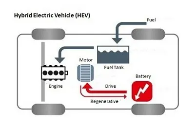
Components of HEV
- Engine
- Electric motor
- Battery pack with controller & inverter
- Fuel tank
- Control module
HEV Operational Principles
It has a gasoline tank similar to a standard car that provides gas to the engine.
Additionally, a set of batteries power an electric motor.
The transmission can be turned by both the engine and the electric motor at the same time.
Examples of HEV
Honda Civic Hybrid, Toyota Prius Hybrid, Honda Civic Hybrid, Toyota Camry Hybrid.
Plug-in Hybrid Electric Vehicle (PHEV)
A PHEV is a hybrid vehicle that has both an ICE and a motor, and is frequently referred to as a series hybrid. This class of electric vehicles has a range of fuel options. This category of electric vehicles is propelled by a rechargeable battery pack and either a conventional fuel (like gasoline) or an alternative fuel (like biodiesel). Electricity can be used to recharge the battery by plugging it into an outlet or an electric vehicle charging station (EVCS).
PHEVs typically have at least two operating modes:
Hybrid Mode, which uses both electricity and gasoline, and All-Electric Mode, in which the motor and battery supply all of the vehicle's energy.
Some PHEVs have an electric-only range of more than 70 miles.
Architecture and Main Components of PHEV
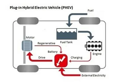
Components of PHEV
- Electric motor
- Engine
- Inverter
- Battery
- Fuel tank
- Control module
- Battery Charger (if onboard model)
PHEV Operating Principles
PHEVs normally start in electric-only mode and continue to run on energy until their battery pack runs out. When they reach highway cruising speed, which is often above 60 or 70 miles per hour, some models switch to hybrid mode. When the battery runs out, the engine kicks in and the car starts running like a regular, non-plug-in hybrid.
An internal combustion engine or regenerative braking can charge PHEV batteries in addition to hooking into an external electric power source. The electric motor functions as a generator during braking, utilising the energy to recharge the battery. Smaller engines can be employed since the electric motor augments the engine's power, improving fuel efficiency without sacrificing performance.
Examples of PHEV
Porsche Cayenne S E-Hybrid , Chevy Volt, Chrysler Pacifica, Ford C-Max Energi, Ford Fusion Energi, Mercedes C350e, Mercedes S550e, Mercedes GLE550e, Mini Cooper SE Countryman, Audi A3 E-Tron, BMW 330e, BMW i8, BMW X5 xdrive40e, Fiat 500e, Hyundai Sonata, Kia Optima, Porsche Panamera S E-hybrid, Volvo XC90 T8.
Fuel Cell Electric Vehicle (FCEV)
Fuel cell electric vehicles (FCEVs), often referred to as zero emission vehicles (ZEVs) or fuel cell vehicles (FCVs), are a subset of electric cars that use "fuel cell technology" to produce the electricity needed to power them. The chemical energy of the gasoline is directly turned into electric energy in this sort of vehicle.
Architecture and Main Components of FCEV
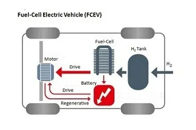
Components of FCEV
- Electric motor
- Fuel-cell stack
- Hydrogen storage tank
- Battery with converter and controller
FCEV Operating Principles
A "fuel cell" electric automobile operates on a distinct set of principles than a "plug-in" electric vehicle. This category of electric vehicles is so-called because the FCEV produces the electricity needed to power it on its own.
Examples of FCEV
Toyota Mirai, Hyundai Tucson FCEV, Riversimple Rasa, Honda Clarity Fuel Cell, Hyundai Nexo.
MAIN COMPONENTS OF AN ELECTRIC VEHICLE
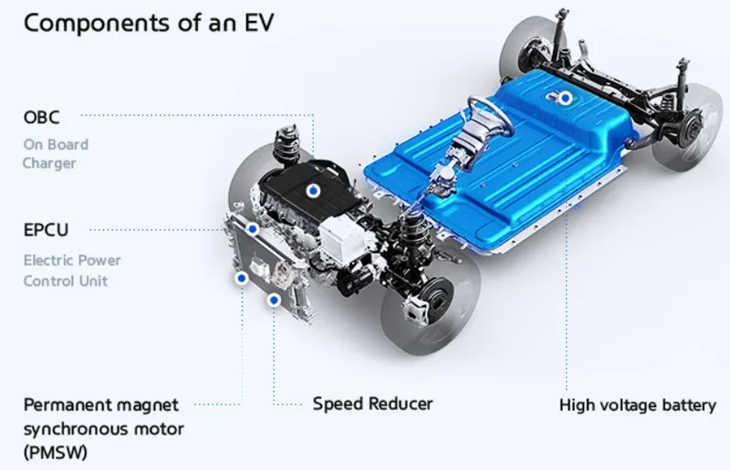
The greatest distinction between electric cars (EVs) and internal combustion engines (ICEs) is that in EVs, the motor is cycled using electricity stored in the battery rather than burning fossil fuel as in ICEs. As a result, EVs do not require the engine or gearbox, two of the most important parts of internal combustion engines. Instead, EVs contain a number of electric power-related parts, including the electric motor, battery, on-board charger, and the electric power control unit (EPCU). All are crucial parts for converting the electricity from the battery into the kinetic force that propels the EV ahead.
Motor
Electric energy is transformed by the motor into kinetic energy, which drives the wheels. The benefits of employing a motor rather than an engine are numerous. To start, the typical automotive noise and vibration are reduced. First-time EV riders are frequently taken aback by how quiet and comfortable the journey is. Additionally, the EV powertrain is smaller than the engine, creating a ton of extra room for effective vehicle design, such as an increased cabin or storage.
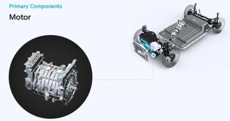
The motor functions in part as an electric generator, converting kinetic energy produced while the car is in neutral (for example, while traveling downhill) into electrical energy that is stored in the battery. When the car slows down, the same energy-saving principle still holds true, ultimately the'regenerative braking system,' as it is known. Some of the electric vehicles (EVs) produced by the Hyundai Motor Group feature a system that allows drivers to adjust the amount of regenerative braking by using paddle shifters on the steering wheel. This feature not only increases fuel efficiency but also makes driving more interesting and enjoyable.
Reducer
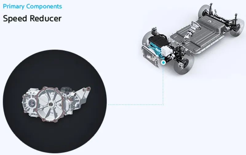
The reducer functions as a type of transmission by efficiently transferring the motor's power to the wheel. However, it has the unique term "reducer" for a reason: unlike transmissions, which adjust the engine RPM to match the driving situation, the reducer must always lower the RPM to an adequate level because the motor has a much greater RPM than an internal combustion engine. The EV powertrain can benefit from the increased torque as a result of the lower RPM.
Battery
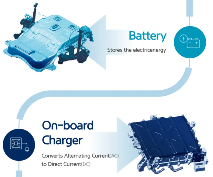
The battery serves as the equivalent of a fuel tank in an internal combustion engine and stores electrical energy. The battery capacity of an EV is frequently what determines its maximum range—the bigger the capacity, the longer the range. In that regard, boosting the capacity could seem like a no-brainer as long driving distances eliminate the bothersome requirement for refueling stops every few miles. The decision is actually not as straightforward because the battery's size and weight have a significant impact on how well the car performs. The larger and heavier battery reduces cabin/storage room and affects fuel economy and energy efficiency. Therefore, increasing the battery's energy density, or using a compact, lightweight battery that stores as much electric energy as possible is the ideal option to enhance performance.
On-board Charger (OBC)
Alternating Current (AC) from slow chargers or portable chargers used with household outlets is converted into Direct Current by the on-board charger (OBC) (DC). Due to this, the OBC may resemble a conventional inverter in appearance, but they serve quite different purposes; the OBC is used for charging, whilst the inverter is used for acceleration and deceleration. Interestingly, since fast chargers already deliver direct current electricity, the OBC is not required for fast charging.
Battery Management System (BMS)
The battery's numerous cells are controlled by the battery management system (BMS), which allows them to function as if they were a single unit. The battery in an EV is made up of tens to thousands of mini-cells, each of which must be in comparable condition to the others in order to maximize the battery's performance and durability.
The BMS is typically integrated into the battery's casing, though it may occasionally be included in the Electric Power Control Unit (EPCU). The BMS primarily monitors the charge and discharge status of the cell, but when it detects a defective cell, it automatically modifies the cell's power status (on or off) using a relay mechanism (the conditional mechanism for opening and closing other circuits).
Battery Heating System
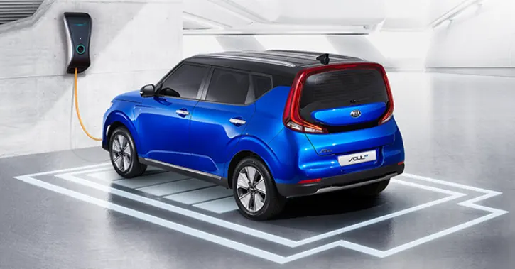
The battery's capacity and charging speed both decrease at lower temperatures. The battery heater's purpose is to maintain the battery's optimal temperature range, avoiding seasonal performance declines, and preserving the maximum driving range. The system continues to work while it is charging, assuring the effectiveness of the charge.
Electric Power Control Unit(EPCU):
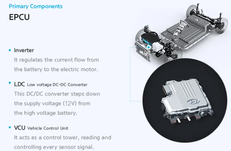
Nearly all of the components that regulate the flow of electric power in a vehicle are effectively integrated into the Electric Power Control Unit (EPCU). It is made up of an inverter, a Low Voltage DC-DC Converter, and a Vehicle Control Unit (VCU).
1. Inverter
The inverter transforms the DC from the battery into AC, which is then utilized to regulate the motor speed. The system plays a key role in maximizing the drivability of the EV because it controls acceleration and deceleration.
2. Low voltage DC-DC Converter
The LDC transforms the high voltage energy from the high-voltage battery of the EV into low-voltage (12V) electricity and supplies it to the different electrical systems of the car. The high voltage in the battery must first be transformed in order for it to be useful for the low voltage electricity that all of the EV's electrical systems require.
3. Vehicle Control Unit
The VCU is likely the most significant part of the EPCU because it serves as the command center for all electric power control systems in the car. It manages almost all of the vehicle's power control systems, including the power supply for the electronic systems, regenerative brake control, A/C load management, and motor control.
SIMULINK Model Of Electric Vehicle:
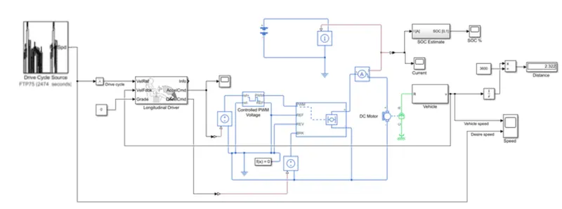
Power Train Block sets used in Simulink: Complete vehicle body is considered as Subsystem as shown below
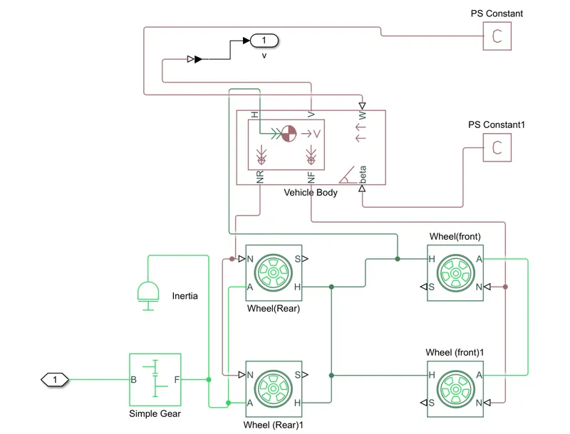
1. Wheels: This Block represents the physical Wheel properites of a vehicle Specified by tire manufacturer.
Four Wheel(2 for rear axle and 2 for front axle) Blocks are used and Each one has same specifications..
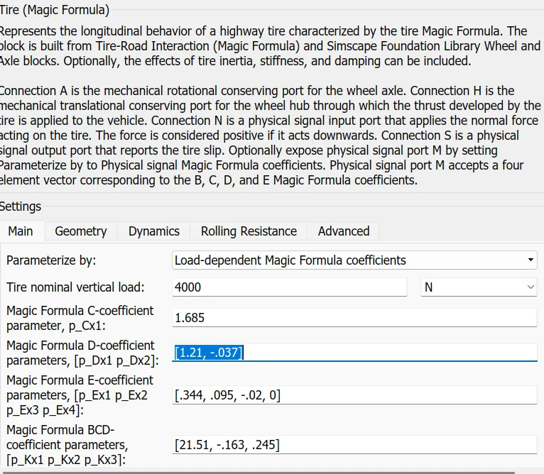
- Wheel Blocks values are considered by default without any changes in all Parameters.
If wheel parameters are specified then that will certainly effects the vehicle performance.
Ports:
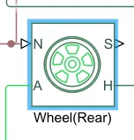
N-Normal Force: This Input Port is used for Force to be applied on Wheel.
Front Wheels N-Port is connected toNF port of vehicle Body.
Rear Wheels N-Port is connected toNR port of vehicle Body.
S-Slip:Physical signal output port associated with the relative slip between the tire and road.
A-AXLE: This Mechanical Translational Port gives Mechanical link between two wheels.
Both Rear and Front Wheels are connected through A-Port.
H-HUB: Mechanical translational port associated with the wheel hub that transmits the thrust generated by the tire to the vehicle body( maintain same speed in all wheels).
All H-Hub ports of Wheels connected to H-port of Vehicle Body.
2.Vehicle Body: This Block gives the Vehicle Body Parameters to be set measured by Physical Vehicle.
In simulation all Parameters are considered as default to reduce simulation time
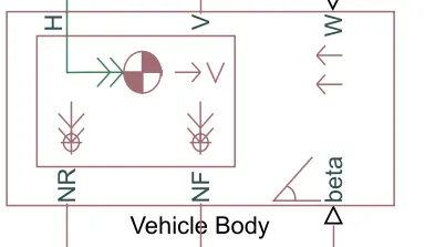
- H,NR and NF ports are connected to Wheels Ports of vehicle.
beta port gives the vehicle body Inclination to the ground in Radians.
W-PortGives the wind velocity applied on front of the Vehicle body(Headwind Speed in m/s).
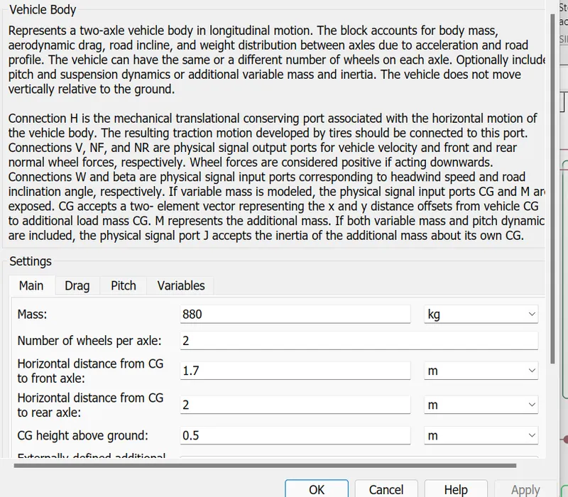
Parameters that have given in vehicle body is shown above figure
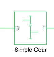
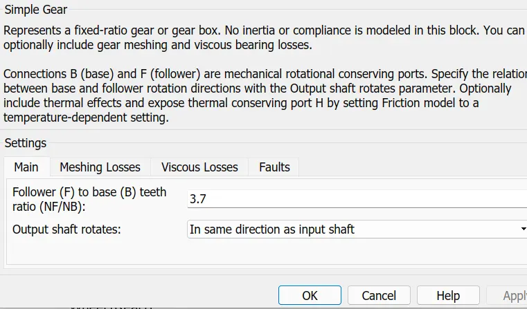
3.GEAR: Represents a fixed-ratio gear from Base(B) to Follower(F).
Gear Ratio is specified by 3.7
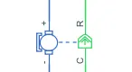
4.DC Motor: This Block represents the electrical and torque characteristics of DC Motor.
Motor Parameters are set as:
No load speed of vehicle=7000 RPM
Rated Load Speed vehicle=5000 RPM
Rated Voltage =330 V
Rated Load of vehicle =75 KW
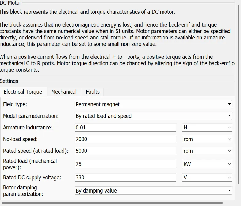
- Remaining all other Parameters( Resistance,Inductance,EMF) are set as Default.
- Blue Part represents electrical Connection to Battery.
- Green part Represents Mechanical Part to be connected to shaft of Gear.
- R-Port is connected to B-Base port of Gear.
- C-Common port is connected to mechanical rotational reference frame.
5.References:
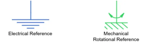
Electrical Reference : Gives the Nuetral Point to the electrical Circuit.
Mechanical Rotational Reference: This Block is considered as a rigid base (ground/frame) point of mechancial body.
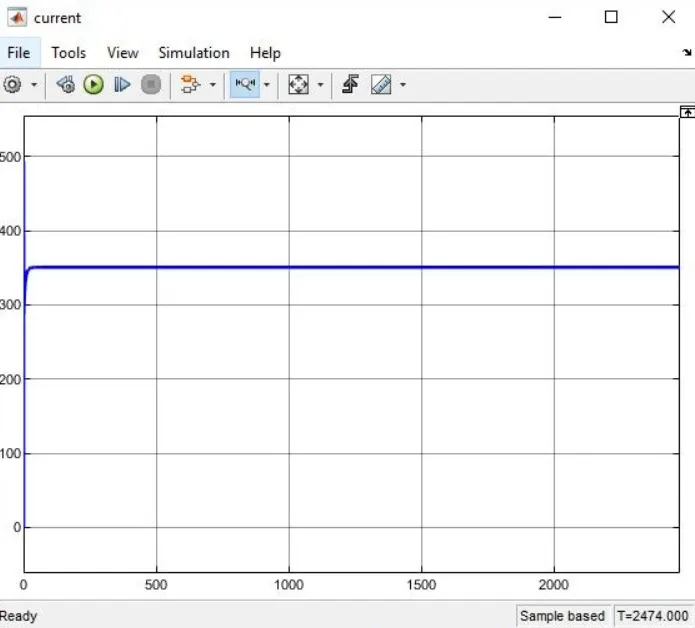
Current Sensor: Sense the current taken by DC Motor and gives the feedback to Battery.
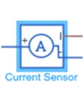
Controlled current Source : Maintain required amount of current to flow from the battery which is sensed from current sensor.

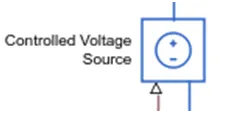
Controlled Voltage Source: Maintain Required amount of voltage to be maintain across DC motor which takes voltage level signal from driver.
PWM: If the input signal has a value greater than the Enable threshold voltage parameter value, the H-Bridge block output is on and has a value equal to the value of the Output voltage amplitude parameter.
If it has a value less than the Enable threshold voltage parameter value, the block maintains the load circuit using Freewheeling diode.
6.H-Bridge: The H-Bridge block output is a controlled voltage that depends on the input signal at the PWM port.
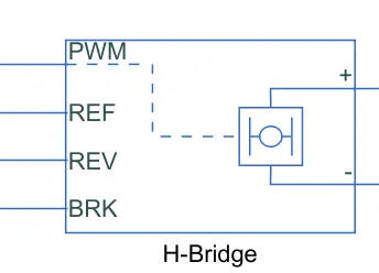
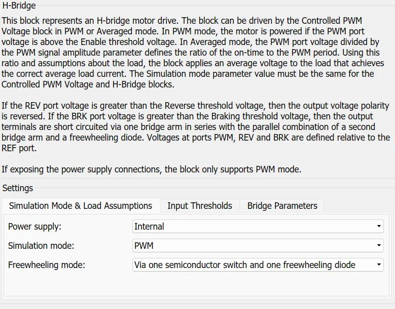
REV: voltage that controls when to reverse the polarity of the H-Bridge block output.
BRK: voltage that controls when to short circuit the H-Bridge block output.
Power supply : Power supply can run in two model Internal and External Mode.
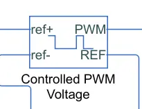
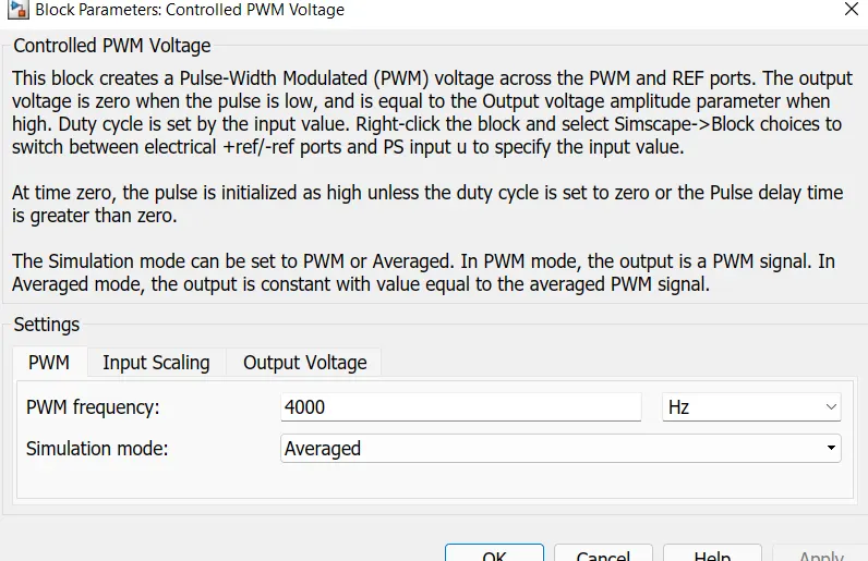
7.Controlled PWM voltage: The Controlled PWM Voltage block represents a pulse-width modulated (PWM) voltage source.
Simulation Mode is AVERAGED to reduce simulation time.
Output voltage: set to 330v (consider as Motor rated voltage)
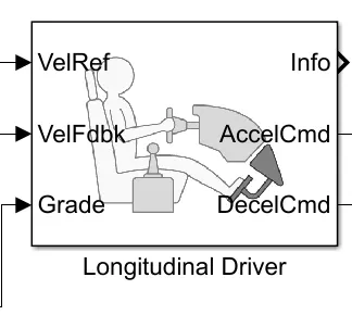
8. Lonitudinal Driver: (Acts as Driver of vehicle)The block generates normalized acceleration and braking commands that can vary from 0 through 1.
It is Speed Tracking Block which uses a PI controller to reduce the error between Reference velocity and output velocity and gives Accleration and brake commands to Motor through H-bridge.
All Parameters are set as default.
Grade is set as zero so, there is no gradeability in Vehicle.

9.Drive Cycle:The Drive Cycle Source block generates a standard or user-specified longitudinal drive cycle. The block output is the specified vehicle longitudinal speed
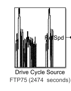
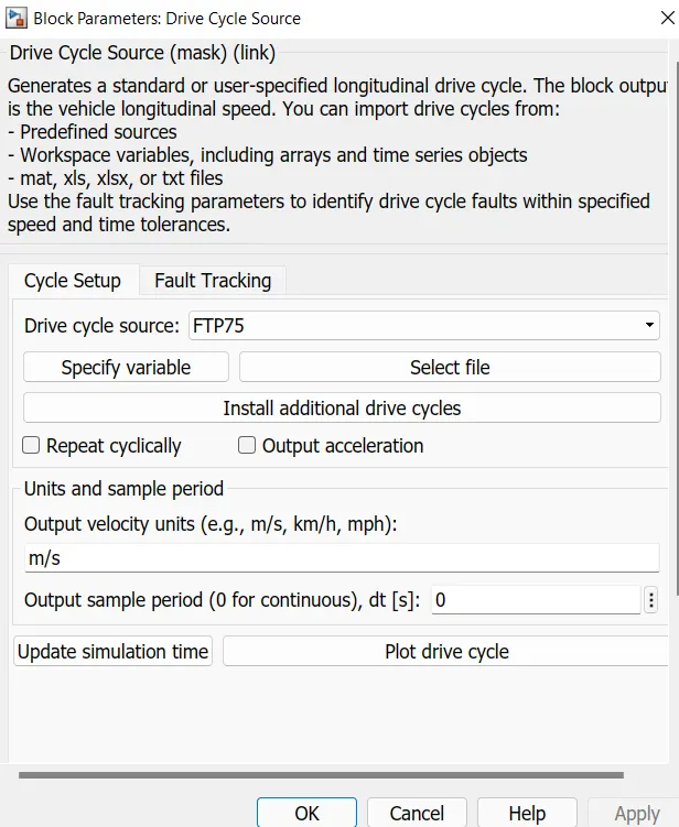
FTP75: used to generate velocity across vehicle and evaluate the vehicle performance.
10.Battery: This block represents the Physical model of battery.

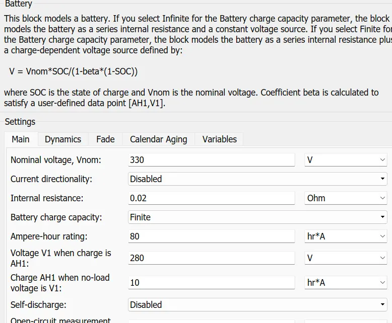
- Battery voltage=Motor rated voltage =330v
- Amphere-Hr rating =80AH
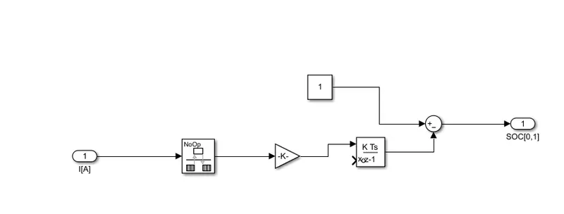
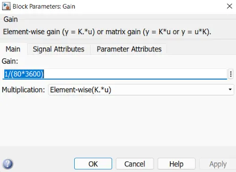
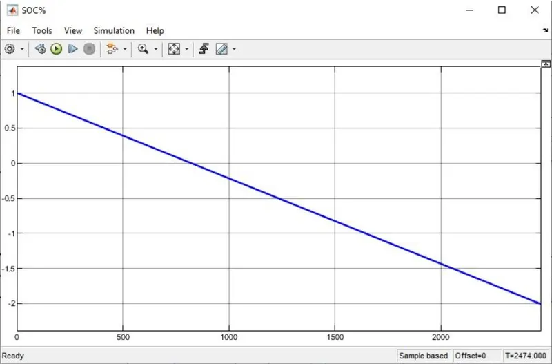
Simulink model of SOC: Current is Integrated and Divide with battery Ampere hour rating (Gain Block)in seconds then subtracted the obtain result from battery full capacity.
Modelling of an EV
- First of all driving cycle used as an input for a driver.
- A longtudinal driver acts as a PI Controller where the vehicle actual speed and refernace speed are measured
- To run the DC motor, converter H bridge is used
- According to the motor AC-AC DC-AC, DC-DC, AC-DC converteris uded to run the motor
- The converter consist of switches and to turn on/off PWM(pulse width modulation) technique is used to control the signal and converter
- The batery is used to measure the current from the vehicle
- Measurement of the speed is constrained by the vehicle body and the tires which are allocated in the subsystem
- Another subsystem contains the data to represents the state of charge of a vehicle in a particular time and driving cycl
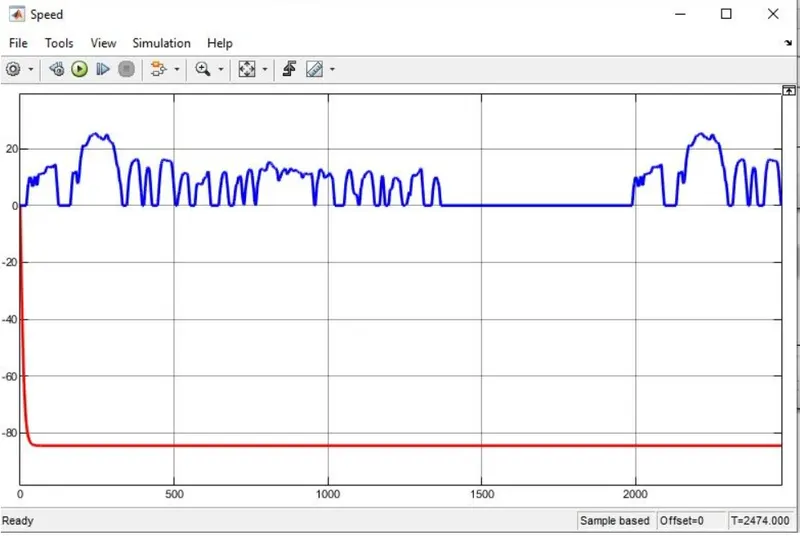
RESULTS - OUTPUT WAVEFORMS
1. STATE OF CHARGE PERCENT - SOC%
2. CURRENT
3. SPEED