Final Project: Design of an Electric Vehicle
Create a MATLAB model of electric car which uses a battery and a DC motor. Choose suitable blocks from Powertrain block set. Prepare a report about your model including following
Objectives:
- System level configurations
- Model parameters
- Results
- Conclusion
AIM:
To create a MATLAB model of an electric car with a battery and a DC motor, by choosing suitable blocks from Powertrain block set.
Electric car:
An electric car is a vehicle which used to run through the battery. It uses the motor to run which uses only electrical energy which stored in the battery. It is the replacement of the IC Engine which run through petrol or diesel. As the same as ICE, it charges its batteries through charging stations with electrical energy instead of fuels by using charging ports chargers. It has low maintenance and eco friendly and also having long life. The efficiency of the electrical cars is little bit higher than the normal ICE type vehicles. The batteries are manufactured with the combination of some chemical as positive and negative by the separator which called electrodes, due to this its protection and safety must be taken as high priority otherwise it leads dangerous effects and explodes as well. They use an electric motor for propulsion. The most common types of motors used are permanent Magnet Synchronous Moto (PMSM) and three phase induction motor. It charges by using both AC and DC type charge technologies.
The main parts of the electric car are,
- Battery with BMS controller
- Converter and inverter
- Motor or generator
- Charger
- Storage device
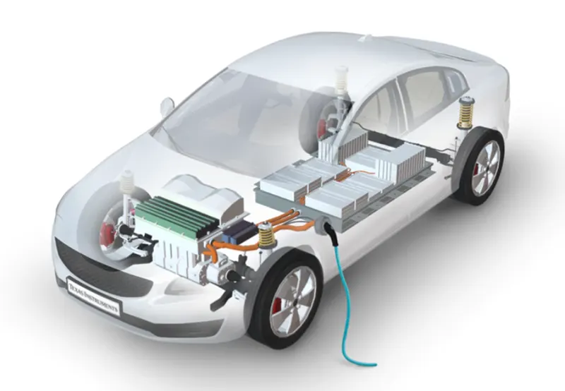
Simulink model of an electric car:
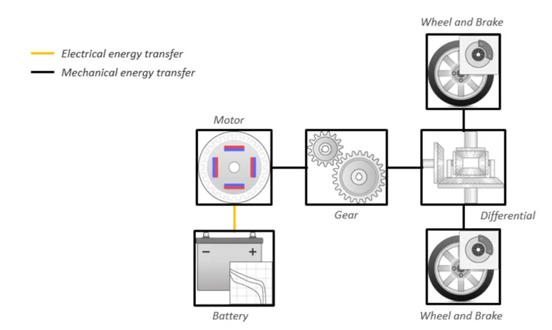
Modelling of an electric car in MATLAB:
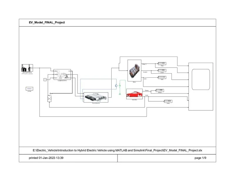
The block diagram for an Electric vehicle which uses a battery and a DC motor is shown,
Now let us look at each of the blocks used to create this MATLAB model.
The main blocks or subsystems of the model are
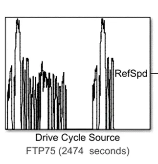
Drive cycle source:
It is located in the Simulink library at
Powertrain Blockset / Vehicle Scenario Builder
Vehicle Dynamics Blockset / Vehicle Scenarios / Drive Cycle and Maneuvers
It is like an input data or called as reference value block which is used as an input to the blocks for the standard signals for the input connection. We used here the drive cycle is the FTP 75 with 2474 sec data.
The parameters of this block is as shown.
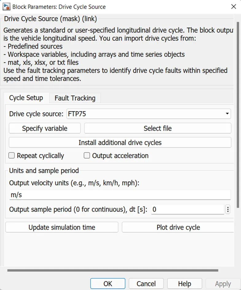
We can use the data as our requited data by changing the settings in the drive cycle source from FTP 75 to WOT and some other.
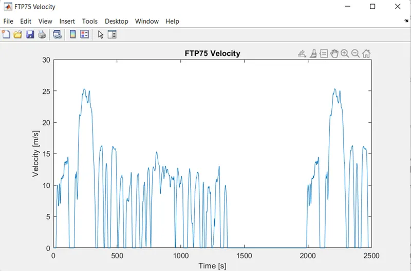
We can see the characteristics of the given drive cycle by clicking on the plot drive cycle block and it look like as shown.
Longitudinal driver model:
It is located at
Powertrain Blockset / Vehicle Scenario Builder
Vehicle Dynamics Blockset / Vehicle Scenarios / Driver, in the Simulink library
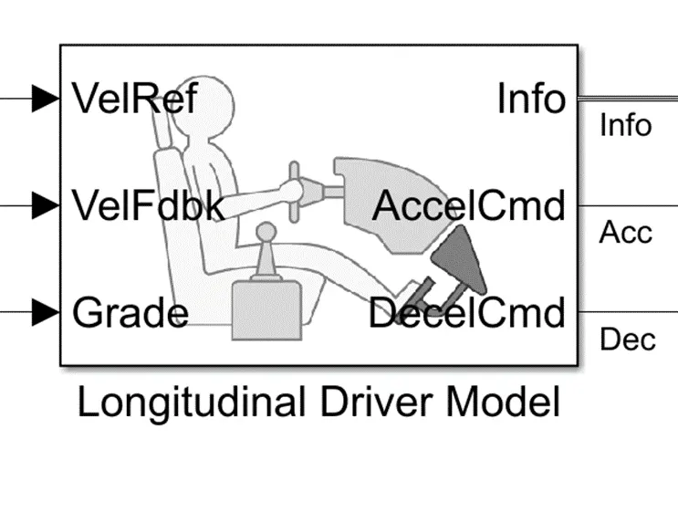
It like a driver which is used to take the charge of driving its acceleration breaking commands as per the given conditions which is called as a reference. It also called as an auto control which it takes the feedback from the vehicle and run as per the given values and changes its commands based on the feedback with the reference values respectively.
This block is used to create a longitudinal speed-tracking controller and it is based on reference and feedback velocities. We can use this block to model the dynamic response of a driver to generate the commands necessary to track a longitudinal drive cycle.
Here in this block the
VEL Ref is used to take the reference values for the driver to drive the vehicle.
Vel Fdbk is used to take the feedback from the output of the given data from the vehicle speed which is called as a velocity.
Accel Cmd is an output signal that gives as an input to the power control unit-controlled voltage source 1 which is connected to the PWM for the purpose of acceleration when the output is reduced to lower than the given reference value.
Decel Cmd is also an output signal that gives as an input to the power control unit-controlled voltage source 2 which is connected to the BRK for the purpose of breaking when the output is becoming higher than the given reference value.
The info is for the signal information to get the physical values and the grade is to measure the road angle respectively.
The block parameters are as shown below,

Power control unit subsystem:
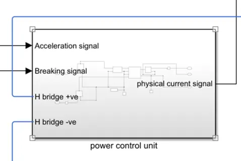
The inner part of the power control unit subsystem is looks like as shown.
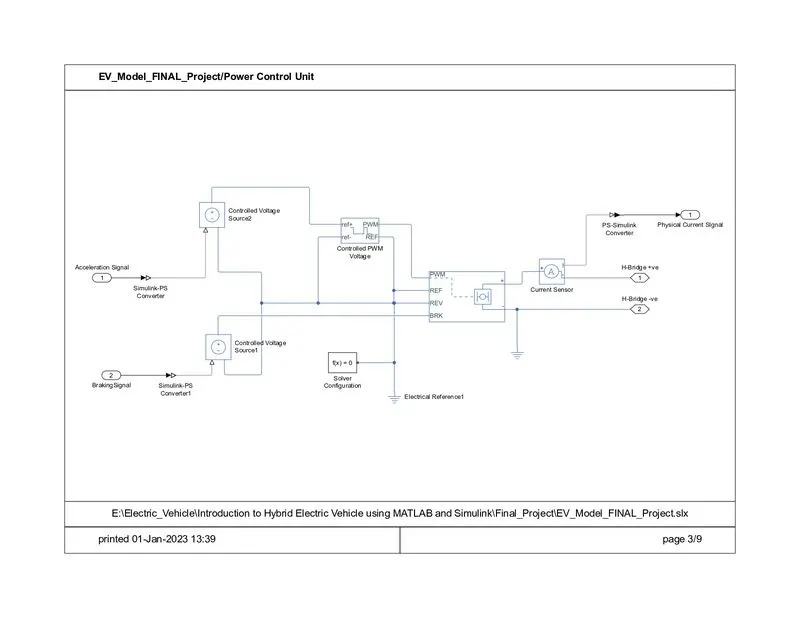
This subsystem has the blocks which are used to create the voltage signals to control the motor speed as per the input drive cycle data.
This subsystem is connected to the longitudinal driver block output ports namely acceleration command and deceleration command.
This subsystem will convert this acceleration and deceleration command into voltage signals using a H-bridge.
Blocks in the controlled power unit;
Controlled voltage source:
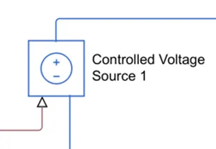
It is located in the Simulink library at Electrical Sources
It is used to control the voltage which is connected to the positive reference of the controlled PWM voltage in the form of a signal by the longitudinal driver model acceleration command. Another controlled voltage source 2 is used to connect to the H bridge BRK terminal the negative sides of both the sources are connected to the electrical reference as shown above.
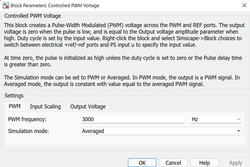
Controlled PWM voltage:
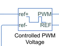
It is located in the Simulink library at Simscape / Electrical / Integrated Circuits
It is used to give the Pulse Width Modulation signals to the H bridge circuit at PWM terminal. The +ve reference terminal of the block is connecter to the controlled voltage source and -ve is connected to the electrical reference, the PWM is connected to the H bridge PWM as said above and REF is connected to the REF and REV terminals of the H bridge. Actual the main aim of the controlled PWM voltage is to give the controlled voltage in the form of a pulses in the DC voltage.
The parameters of this controlled PWM voltage are as above.
H-Bridge:
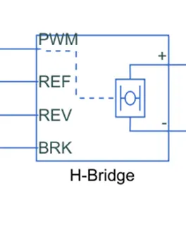
It is located in the Simulink library at Simscape / Electrical / Semiconductors & Converters / Converters.
This block is used to change the polarity of the voltage applied across the DC motors so as to run the motor in forward and reverse direction as per the input command.
As the name indicates that the H symbol in the block is connected to the DC motor and the PWM, REF, REV, BRK are used to control the block DC motor.
The parameters of the H-Bridge are as shown,
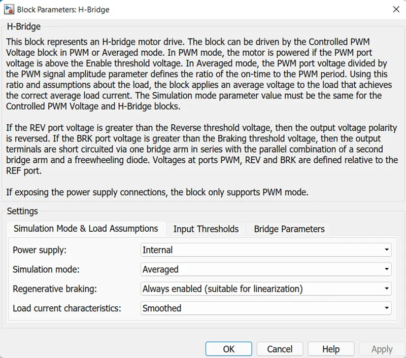
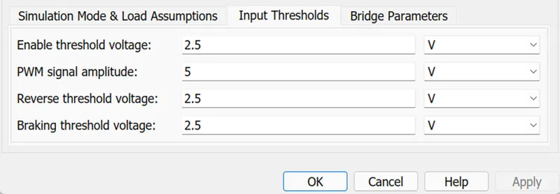
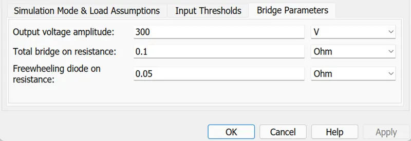 Here we used the output voltage amplitude is 300 V so the battery nominal voltage range is to be in the range of 300 V for 1C rate.
Current sensor block:
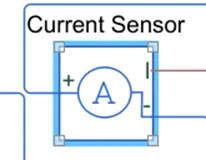
It is located in the Simulink library at Electrical Sensors.
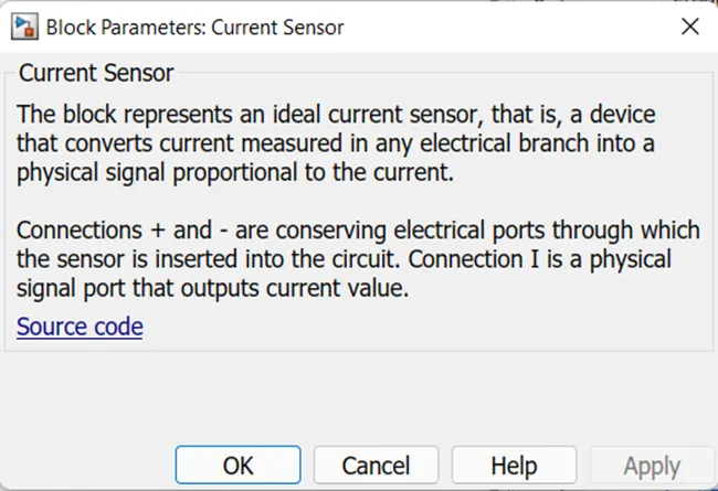
This is used to measure the current flowing through the H-bridge. The +ve and -ve terminals of the current sensor are connected to the DC motor and H-Bridge block respectively and the signal is connected to the controlled current source in the battery subsystem as a physical input signal from the H-Bridge circuit.
The block and its parameters are shown below,
Electrical reference:
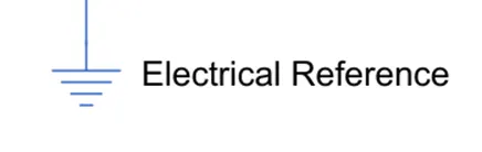
It is located in the Simulink library at Electrical Elements.
It is used to connect all the terminal of the negative signals and the reference values as the ground.
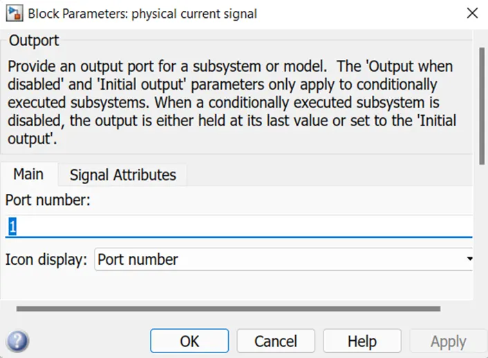
Outport:
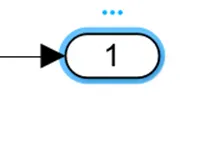
It is located in the Simulink library at
Simulink / Commonly Used Blocks.
Simulink / Ports & Subsystems. And some other areas.
It is used to connect this output to the subsystem which is used for the connection to the outputs.
Inport:
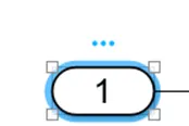
It is located in the Simulink library at
Simulink / Commonly Used Blocks.
Simulink / Ports & Subsystems. And some other areas.
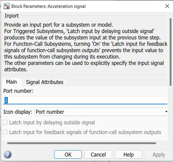
It is used to connect to the ports or blocks to the inner part of the subsystem.
The parameters of the inport is as shown below.
Connection port:
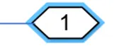
It is located in the Simulink library at
Simscape / Utilities
Powertrain Blockset / Utilities / Simscape, and some other areas.
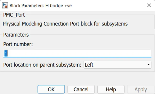
It is used to connect the outside terminals or blocks of the subsystem as well as inner blocks from the outside.
The parameters of the connection port is shown below,
Ps-Simulink converter:
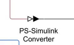
It is located in the Simulink library at utilities.
It is used to connect the line from physical signal to Simulink which act as an converter.
DC motor:
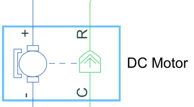
It is located in the Simulink library at Simscape / Electrical / Electromechanical / Brushed Motors.
It is used to convert the electrical energy to mechanical energy. In this electric vehicle model, we have used type is permanent magnet DC motor. This motor can also act as a generator in the case of regenerative braking.
In this block the motors the electrical side is represents with the blue colour and the mechanical side is represents with the green as well with the combination of shaft which is in the dotted line. here the motors +ve and -ve terminals are connected to the H-Bridge +ve and -ve terminals respectively with the electrical reference in -ve side. And the mechanical side Rand C terminal are connected to the vehicle body simple gear terminal and to the mechanical rotational reference respectively.
The parameters of the DC motor are shown below,
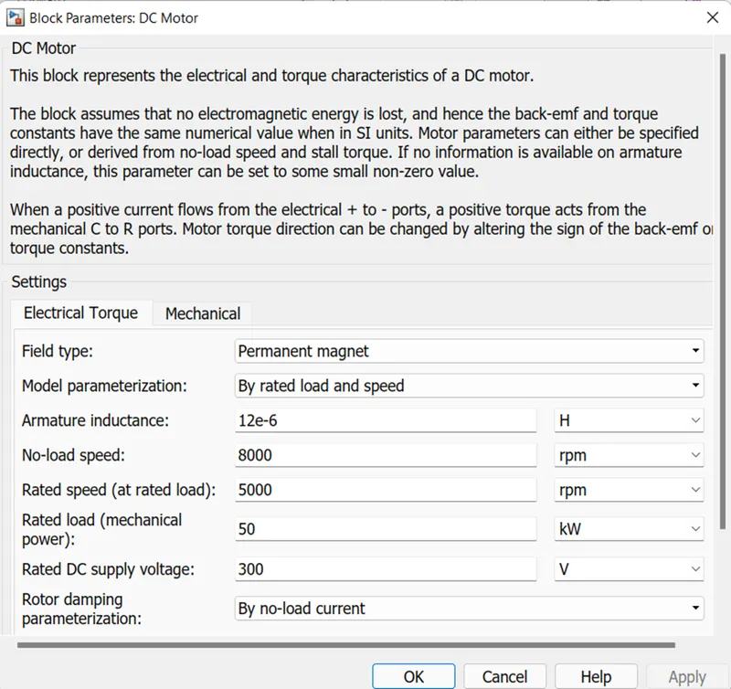
This block represents the electrical and torque and mechanical characteristics of a DC motor.
Here we used the voltage that is DC voltage value is 300 V with the power of 50 Kw. The rated and no-load speed of the motor are given as 5000 and 8000 Rpm respectively by keeping all other parameters are same. The mechanical characteristics also be kept as same without any change.
Mechanical rotational reference:
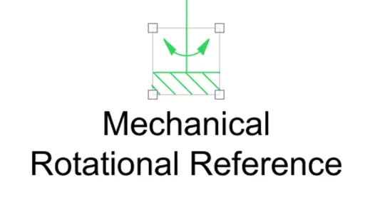
It is representing as a mechanical ground reference point that is as a frame part which is used to connect rotational parts to the ground.
Battery:
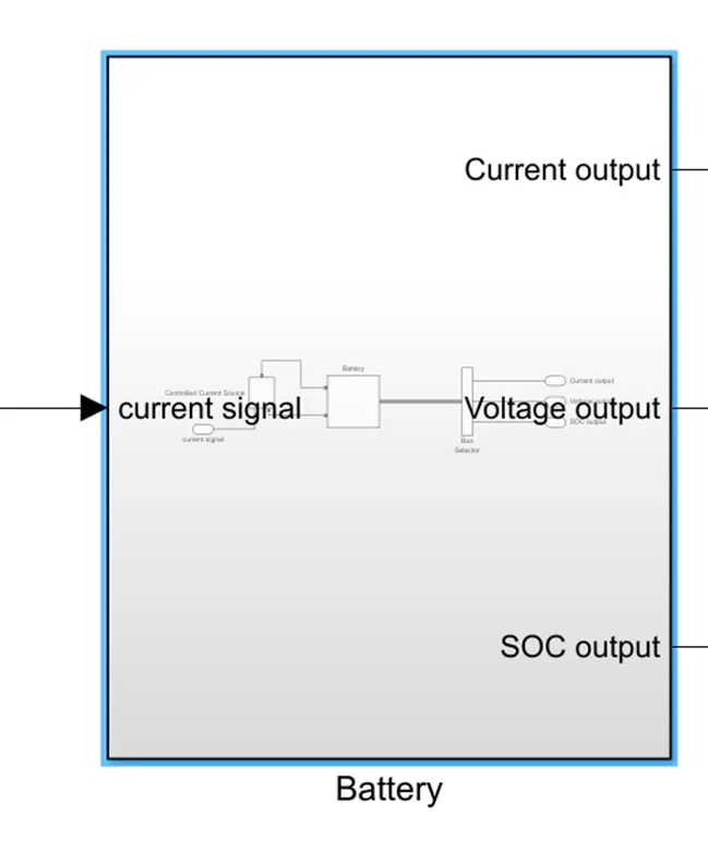
It is used to give the battery connection to the DC motor by the controlled current source which will get the current signals for the control part from the power control unit current sensor physical signal.
The subsystem of the battery is shown below,
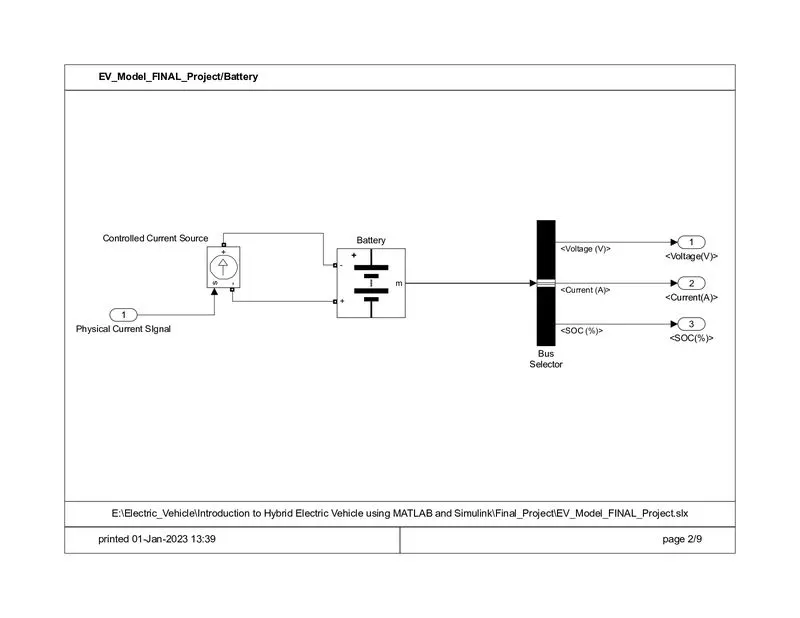
In this subsystem we have used a battery block, a controlled current source block bus selector and Inport and outport blocks.
Battery block:
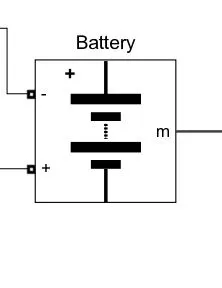
The battery that is placed in the Simulink library is
Simscape / Electrical / Specialized Power Systems / Electric Drives / Extra Sources
This battery block represents a simple battery model. The block models the battery as a series internal resistance and a current voltage source.
We can say that the battery is the one of the main important part or the block in the vehicle and model as well. By connecting this terminasl to the controlled voltage source it supplies controlled signals to discharge and also charging in the regenerative type as well. The output signals of the battery are taken are SOC, current, and voltages.
The block parameters of the battery are shown below,
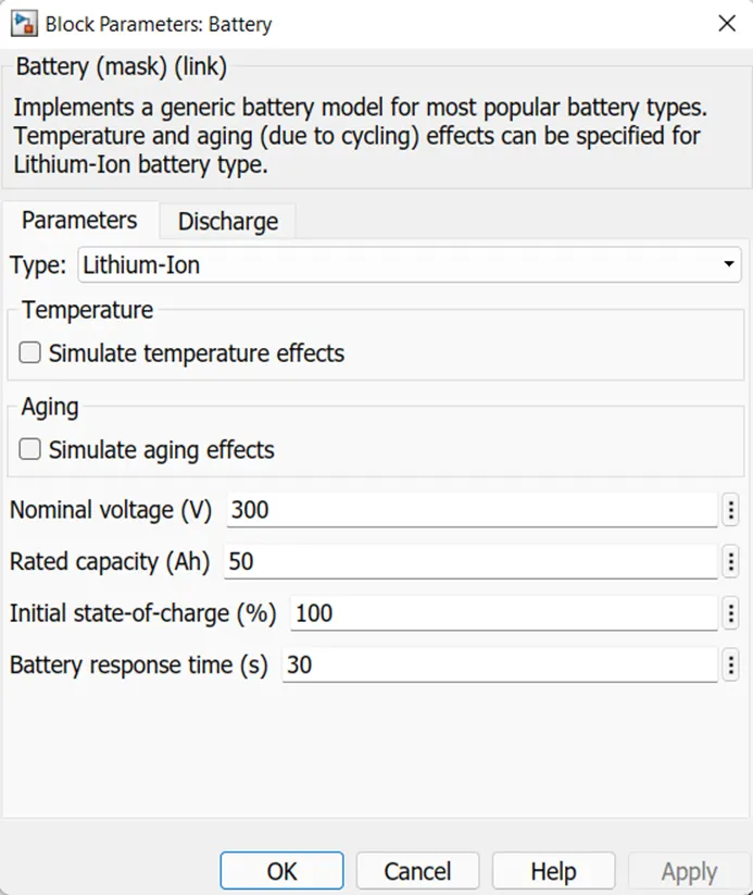
 Here we changed the nominal voltage value to 300 V. its rated capacity to 50 Ah in the parameters section.
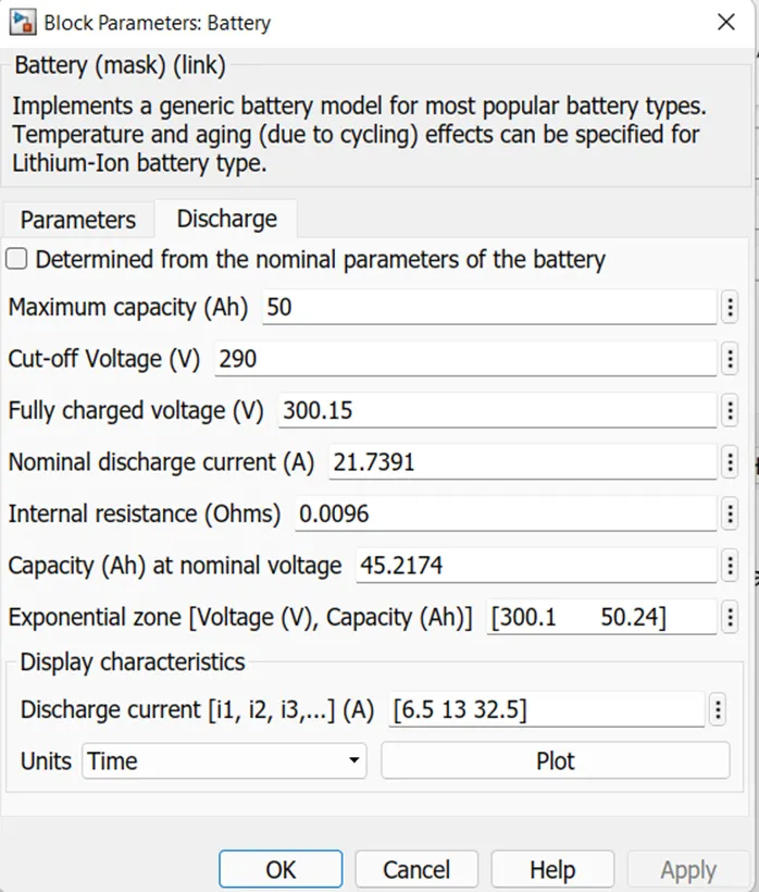
In the discharge section the cut-off voltage to 290V, its max capacity to 50Ah, fully charge to 300.15V and the exponential zone which is the max value which not to exceed are (Voltage (V), Capacity (Ah) are 300.1 and 50.24 respectively by keeping all other parameters are as same as shown above.
Controlled current source block:
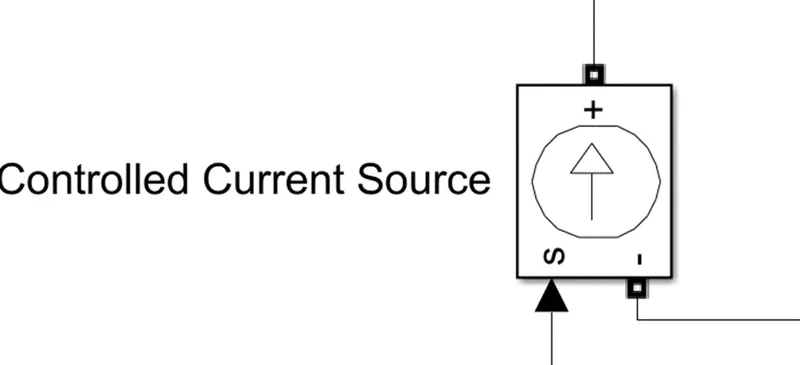
It is located in Simulink library at Simscape / Electrical / Specialized Power Systems / Fundamental Blocks / Electrical Sources
There is no need to use the parameters of the controlled current source, so the parameters block of the controlled current source is like,
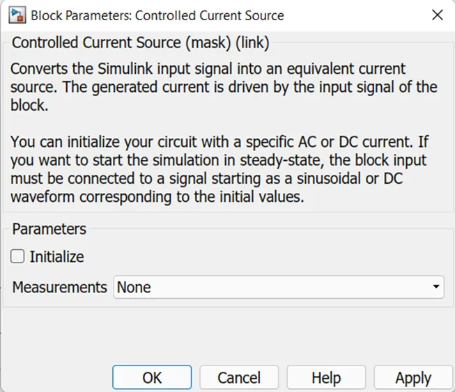
The Controlled Current Source block converts the Simulink input signal into an equivalent current source. The generated current is driven by the input signal of the block which is shown as symbol of ‘s’. The positive current direction is as shown by the arrow in the block icon. This control source can used for both AC and DC current controls. Without giving any signal or values to the control as input it will not work. Here the controlled current source +ve and -ve terminals are connected to the battery +ve and -ve terminals respectively as shown. The input signal S is connected to the power control unit current sensor signal I which is the physical signal.
Bus selector:
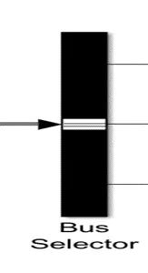
It is located in many places in the library they are,
Simulink / Commonly Used Blocks (or)
Simulink / Signal Routing (or)
HDL Coder / Signal Routing
The bus selector is used to block the output signals which are given as an input to that bus selector block. This is used to select by the designer to which have to generate which not that can be identified by the parameter block of the bus selector which is looks like.
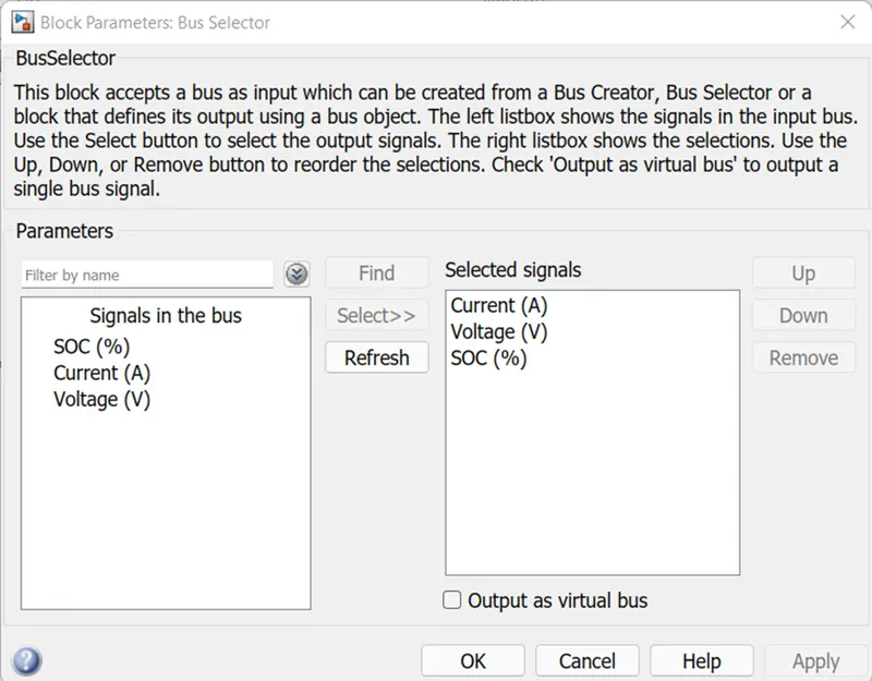
Here The left-side box shows the signals in the input bus, Use the Select button to select the output signals. The right-side box shows the selections, Use the Up, Down, or Remove button to reorder the selections. The block can output the selected elements separately or in a new virtual bus.
The outputs that we selected from out comes are SOC current and voltage.
Vehicle body:
It is the system which shows the main parts of the vehicle that effects by the nature and the inputs given by the batteries and gives the feedback for the control system.
The outlook of the vehicle body subsystem is as below.
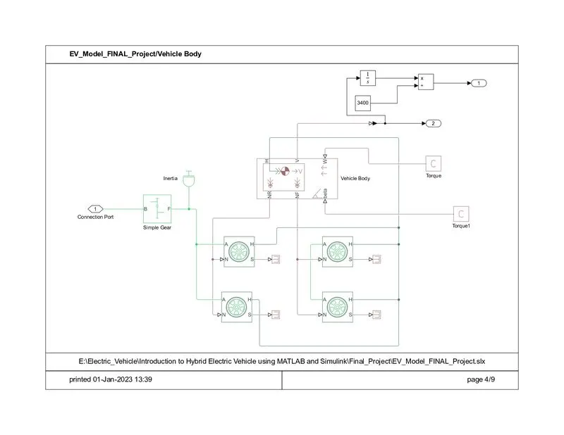
The blocks of this subsystem have simple gear, inertia, tires, vehicle body, and physical constants and inport and outport blocks.
Simple gear:
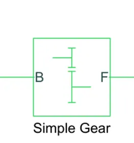
It is located in the library of the Simulink at Simscape / Driveline / Gears
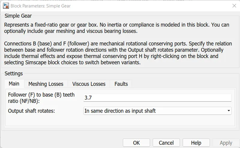
It is the representation for the gear box in the vehicle, it seems similar as a real gear box we can include meshing and bearing losses if we need.
It is located between the connection of the motor terminal R and A is the mechanical rotational conserving port by the gear terminals B and F respectively.
The parameters block of the simple gear block system is as below,
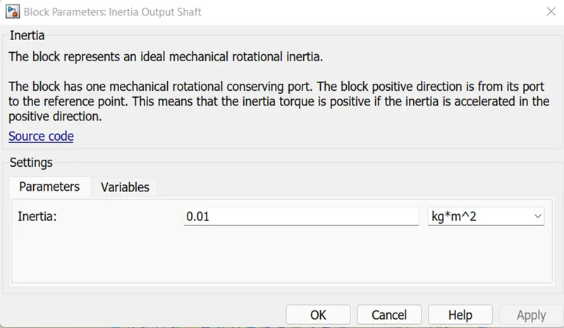
Inertia:
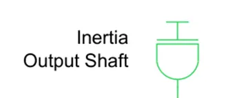
It is used to represent the ideal mechanical rotational inertia which is the reference port to give the positive inertia torque with the terminal used to connect to the reference one.
The parameters block of the inertia is shown,
Tires:
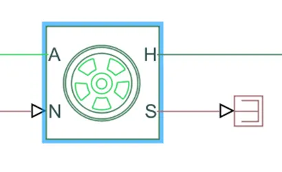
As we seen above that the tires are used in the vehicle body which is having the 2 tires each per axle which moves along with the given throttle value as left and right front and rear blocks. It is the mathematical model of the design or block of the tire which have the same parameters and effects which are designed In the model as real. The effects for the real one is applied to the tire as same.
Here the names A indicates the mechanical rotational conserving port for the wheel axle. Connection H is the mechanical translational conserving port for the wheel hub through which the thrust developed by the tire is applied to the vehicle. Connection N is a physical signal input port that applies the normal force acting on the tire. Connection S is a physical signal output port that reports the tire slip. We not consider the slip in this subsystem so we connected the S terminal to the terminate physical signal to not to generate the warnings to the not connected ports.
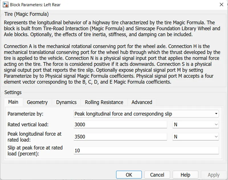
The parameter blocks of the tire block is as shown.
Vehicle body:
It is located in the Simulink library at Simscape / Driveline / Tires & Vehicles.
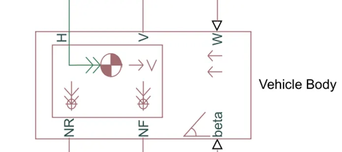
The vehicle body is used to represent the vehicle in practical way it has the same inputs as a real-world vehicle requires like drag values, pitch, variables, wind velocity and road angles etc.
The connection ports that is Connection H is the mechanical translational conserving port associated with the horizontal motion of the vehicle body. Connections V, NF, and NR are physical signal output ports for vehicle velocity and front and rear normal wheel forces, respectively, In this ports Wheel forces are considered positive if acting downwards. Connections W and beta are physical signal input ports corresponding to headwind speed and road inclination angle, respectively.
This block has an option to include an externally-defined mass and an externally-defined inertia. The mass, inertia, and centre of gravity of the vehicle body can vary over the course of simulation in response to system changes.
As it says above that the connection of the vehicle body ports which are inputs that is H is connected to the tire blocks H terminal. NR and NF to the rear wheel N and front wheel N terminals. W and beta are the optional here we connected both to the physical signal (PS) constant with the value of 0. V is the output port which gives the velocity value that is it gives the speed that a vehicle is be gone.
The parameters block of the vehicle body is given,
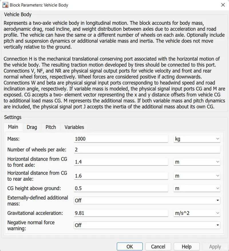
Here we considered Mass of the vehicle = 1000 kg
Front and rear axle with 4 wheels, we use two per axel as mentioned is 2
We can change the parameters as our requirement, but place the standard values as same as above.
Product and integrator:
As the name it self indicates that the both are used to product and divide purpose and integration respectively.
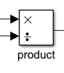
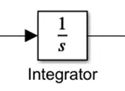
These both are used to calculate the values of the distance travelled by the vehicle through the mathematical model as shown in the sub system.
Scope:
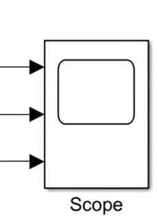
It is also located at different places as,
Simulink / Commonly Used Blocks
Simulink / Sinks
HDL Coder / Commonly Used Blocks
HDL Coder / Sink
In library
It is used to display the signals generated during simulation.
Display:
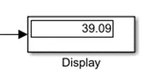
It is located in the library Simulink at Simulink / Sinks.
It is used to display the value that connected to this block in the form of physical form.
Unit conversion:
It is used to convert automatically from Km/hr to m/sec as well.
powergui:
It is located at Simscape / Electrical / Specialized Power Systems / Fundamental Blocks.
it is used with simulation of power systems and power electronics.
It is used for the analysis and measurement of parameters like voltage, current, active power, reactive power like that.
It gives the steady state values of the system.
Solver configuration:
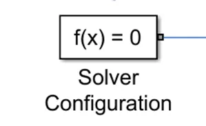
It is placed in the power control unit for the mathematical values in the model solver settings at the simulation time
To get the results of this model we have to keep the stop time to 2474 sec or above because of the given drive cycle source with FTP (2474 seconds).
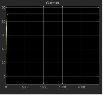
By running the model, we get the results as below for.
Battery current:
Battery voltage:
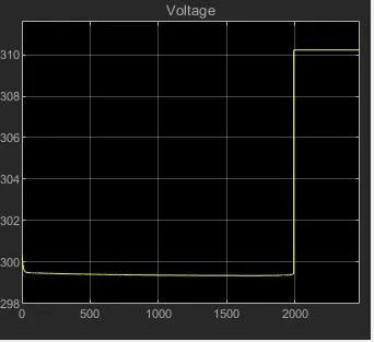
In this if we observe that the voltage varies a little bit of about 299.2 to 300.8 V due to changes speeds, acceleration and deceleration values in the model. Mainly if we observe here that it seems similar to the current values but in the opposite direction to each other. with same values because of its opposite nature. The voltage value after the running time is 300.6V.
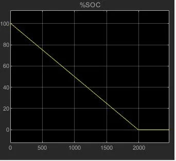
SOC:
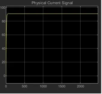
Current signal:
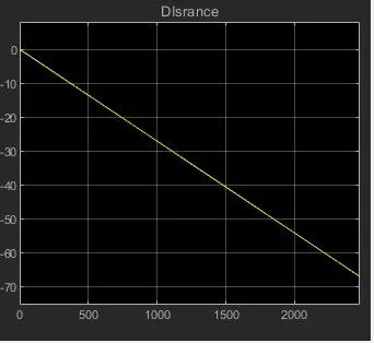
Distance:
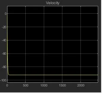
Velocity with drive cycle: