Week-7 Challenge: DC Motor Control
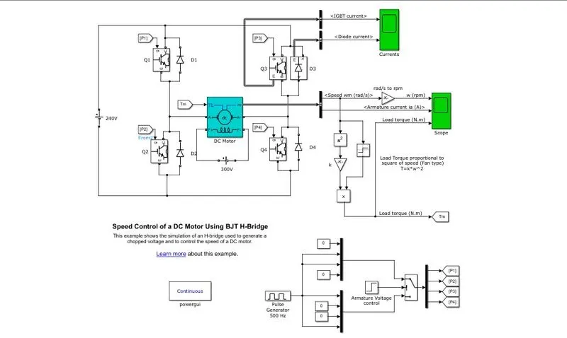
Q01. A. Explain a MATLAB demo model named ‘Speed control of a DC motor using BJT H-bridge’.
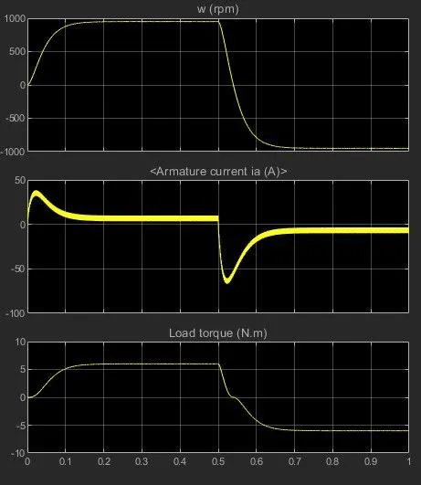
B. Comment on the armature current shoot-up from the scope results.
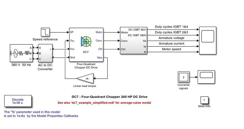
C. Refer to the help section of ‘The Four-Quadrant Chopper DC Drive (DC7) block’. Compare it with the H-bridge model.
Objective -
- To explain a MATLAB demo model named ‘Speed control of a DC motor using BJT H-bridge’.
- To comment on the armature current shoot-up from the scope results.
- To compare the ‘The Four-Quadrant Chopper DC Drive (DC7) block’ with the H-bridge model.
Theory -
Speed Control of a DC Motor using BJT H-Bridge -
- The Bipolar Junction Transistor (BJT) when used for power switching applications, operates as an IGBT.
- When it is conducting (BJT operating in the saturated region), a forward voltage Vf is developed between collector and emitter (in the range of 1 V).
- Therefore, the IGBT block can be used to model the BJT device.
- The IGBT block does not simulate the gate current controlling the BJT or IGBT.
- The switch is controlled by a Simulink signal (1/0).
- The DC motor uses the preset model (5 HP 24V 1750 rpm).
- It simulates a fan type load (where Load torque is proportional to square of speed).
- The armature mean voltage can be varied from 0 to 240 V when the duty cycle (specified in the Pulse Generator block) is varied from 0 to 100%.
- The H-bridge consists of four BJT/Diode pairs (BJT simulated by IGBT models).
- Two transistors are switched simultaneously: Q1 and Q4 or Q2 and Q3.
- When Q1 and Q4 are fired, a positive voltage is applied to the motor and diodes D2-D3 operate as free-wheeling diodes when Q1 and Q4 are switched off.
- When Q2 and Q3 are fired, a negative voltage is applied to the motor and diodes D1-D4 operate as free-wheeling diodes when Q2 and Q3 are switched off.
Simulation -
- The motor starts in the positive direction with a duty cycle of 75% (mean DC voltage of 240V).
- At t= 1.0 sec., the armature voltage is suddenly reversed and the motor runs in the negative direction.
- Scope shows motor speed, armature current and load torque and 'Currents' shows currents flowing in BJT Q3 and diode D3.
Armature Current Shoot-up -
- At t = 1.0 sec, the armature voltage is reversed and the motor is made to run in reverse direction.
- Due to sudden reversal of voltage the motor armature draws heavy current in order to run the motor in reverse direction.
- This sudden increase in armature current is known as Armature Current Shoot-up.
- The armature current shoot-up can be reduced by decreasing the pulse width.
Four-Quadrant Chopper DC Drive (DC-7) Block -
- The 200 HP DC motor is separately excited with a constant 150 V DC field voltage source.
- The armature voltage is provided by an IGBT converter controlled by two PI regulators.
- The converter is fed by a 515 V DC bus obtained by rectification of a 380 V AC 50 Hz voltage source.
- In order to limit the DC bus voltage during dynamic braking mode, a braking chopper has been added between the diode rectifier and the DC7 block.
- The first regulator is a speed regulator, followed by a current regulator.
- The speed regulator outputs the armature current reference (in p.u.) used by the current controller in order to obtain the electromagnetic torque needed to reach the desired speed.
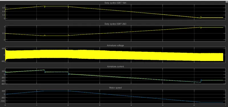
- The speed reference change rate follows acceleration and deceleration ramps in order to avoid sudden reference changes that could cause armature over-current and destabilize the system.
- The current regulator controls the armature current by computing the appropriate duty ratios of the 5 kHz pulses of the four IGBT devices (Pulse Width Modulation).
- For proper system behaviour, the instantaneous pulse values of IGBT devices 1 and 4 are opposite to those of IGBT devices 2 and 3. This generates the average armature voltage needed to obtain the desired armature current.
- In order to limit the amplitude of the current oscillations, a smoothing inductance is placed in series with the armature circuit.
Comparison between BJT H-Bridge and Four Quadrant Chopper -
| BJT H-Bridge | Four Quadrant Chopper |
|
|
Q02. Develop a 2-quadrant chopper using simulink & explain the working of the same with the relevant results.
Objective -
To develop a 2-quadrant chopper using simulink and explain its working.
Model -
The simulink model for the 2 quadrant chopper is shown below -
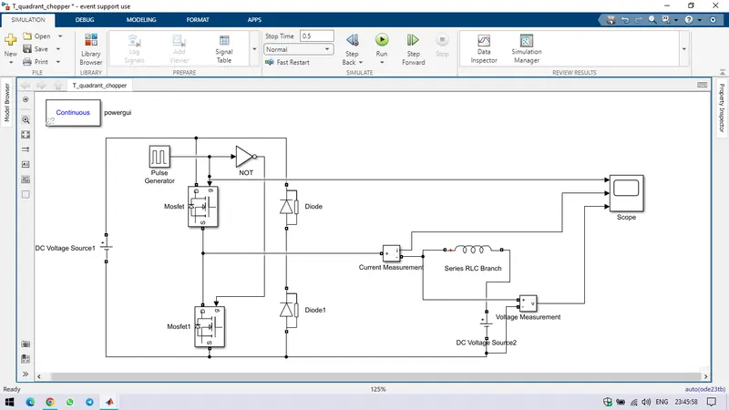
- For the motor load, a inductor is taken with the value of 1e^-3.
- A dc voltage source 1 of 30 V is provided for the circuit and a dc voltage source 2 of 12V with motor load.
- During first pulse, CH1 is on and the current flows from source to load.
- During this inductor stores senergy.
- When CH1 turns OFF, the FD starts conducting and direction of load current is reversed.
- When CH2 turns ON, the current will be flowing towards the source and the load current will be negative.
- The current completes its path through diode D2.
Results -
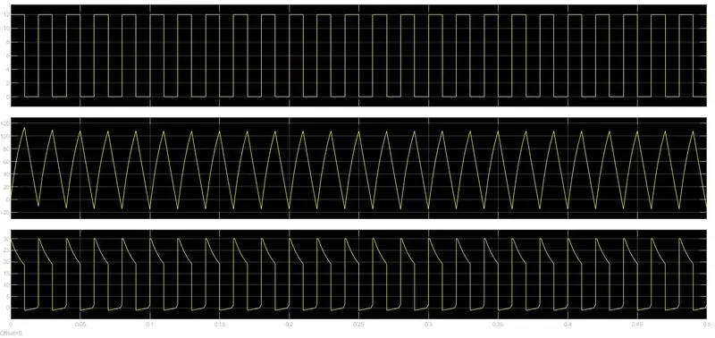
The input gate pulse, load current and load voltage is shown below -
Q03. Explain in a brief about operation of BLDC motor.
Objective -
To explain in brief about operation of Brushless DC Motor.
Theory -
Brushless DC Motor -
- A brushless DC electric motor (BLDC motor or BL motor), also known as an electronically commutated motor (ECM or EC motor) or synchronous DC motor.
- It is a synchronous motor using a direct current (DC) electric power supply.
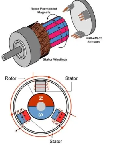
- It uses an electronic controller to switch DC currents to the motor windings producing magnetic fields which effectively rotate in space and which the permanent magnet rotor follows.
- The controller adjusts the phase and amplitude of the DC current pulses to control the speed and torque of the motor.
- This control system is an alternative to the mechanical commutator (brushes) used in many conventional electric motors.
Working Principle -
- BLDC motor works on the principle similar to that of a conventional DC motor, i.e., the Lorentz force law which states that whenever a current carrying conductor placed in a magnetic field it experiences a force.
- As a consequence of reaction force, the magnet will experience an equal and opposite force. In case BLDC motor, the current carrying conductor is stationary while the permanent magnet moves.
- When the stator coils are electrically switched by a supply source, it becomes electromagnet and starts producing the uniform field in the air gap.
- Though the source of supply is DC, switching makes to generate an AC voltage waveform with trapezoidal shape.
- Due to the force of interaction between electromagnet stator and permanent magnet rotor, the rotor continues to rotate.
- With the switching of windings as High and Low signals, corresponding winding energized as North and South poles.
- The permanent magnet rotor with North and South poles align with stator poles causing motor to rotate.
Advantages of BLDC Motor over DC Motor -
- It has no mechanical commutator and associated problems.
- High efficiency due to the use of permanent magnet rotor.
- High speed of operation even in loaded and unloaded conditions due to the absence of brushes that limits the speed.
- Smaller motor geometry and lighter in weight than both brushed type DC and induction AC motors.
- Long life as no inspection and maintenance is required for commutator system.
- Higher dynamic response due to low inertia and carrying windings in the stator.
- Less electromagnetic interference.
- Quite operation (or low noise) due to absence of brushes.