Final Project: Design of an Electric Vehicle
Electrical Vehicles are rapidly replacing conventional ICE vehicles across the globe. But selecting the right architecture and components is a difficult task because of the resources available. A vehicle is basically an electromechanical system with a large number of subsystems. The close integration of all the sub-systems is essential for deriving the most out of it and making it more efficient. Testing all the combination physically is neither practically not feasible .So, a powerful simulating tool like Matlab and simulink is essential to evaluate important parameters such as range, acceleration, power, and cost of the system in order to compare and validate the design.
Components of EV:
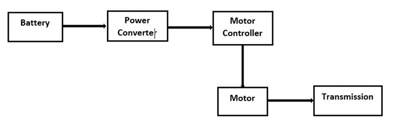
Battery: The battery of an electric car can be charged through the use of ordinary grid electricity at a specialized power station. But aside from the conventional lithium-ion battery technologies, there are also other major battery technologies which can be used for electric cars.
Lithium-Ion Batteries :This battery technology gives extra performance and range. However, it also carries the highest price tag. Lithium-ion batteries are lighter than Lead acid and Nickel metal. These are also the batteries used in digital cameras and smartphones.
Lead Acid Batteries : This battery technology is the most popular. It is also the cheapest among the battery technologies. What’s good about it is it’s 97% recyclable.
Nickel Metal Hydride Batteries : This battery technology provides higher output and better performance but it costs much more than lead-acid batteries.
Motor Controller : The motor controller of an electric car administers its complete operation and the distribution of its power at any given moment. It acts as a floodgate between the motor and batteries. It helps monitor and regulates all key performance indications such as the vehicle’s operator, motor, battery, and accelerator pedal. It has a microprocessor which can limit or redirect current. It is used to either improve the mechanical performance of the car or suit the operator’s driving style. There are also more refined controllers which are capable of greater accuracy and thus, higher efficiency.
Electric Motor : Unlike a gasoline engine with lots of moving parts, a motor only has one moving part. This makes it a very reliable source of motive power. Choosing an electric motor depends on the car’s system voltage. They can be structured to use either AC or DC current. AC motors are less expensive and lighter compared to DC motors. They are also more common and they tend to suffer from less mechanical wear and tear. However, AC technology requires a more refined or sophisticated motor controller.
MATLAB Simulink is a powerful tool that lets you design and validates your system. This feature-laden software with its computing prowess is a good software to accelerate your design phase. With powertrain and simscape block, its become esy to develop and model Electric vehicle .In this project, we will see how we can use MATLAB to design an EV power train.
Electric Vehicle Model
In this project, simple EV power train is modelled and simulated it with actual forces and resistance the vehicle has to endure in real world scenarios. We have coupled it with blocks such as vehicle body, tires, etc, in order to include data such as wheel friction, air resistance, rolling resistance, etc. Since we are only testing how we can utilize this software to simulate different scenarios, we avoided using data from a specific vehicle.
Drive Cycle Source
Generates a standard or user-specified longitudinal drive cycle. The block output is the vehicle longitudinal speed. You can import drive cycles from:
- - Predefined sources
- - Workspace variables, including arrays and time series objects
- - mat, xls, xlsx, or txt files
- The signal editor block is used for designing signals. The signal can be used in a user-defined manner. We can use the signal editor block to feed any customizable data showing the speed of the vehicle to the longitudinal driver block.
Note: the signal editor block is not used , but we can use the signal editor block in place of a Drive cycle source.
Longitudinal Driver Block
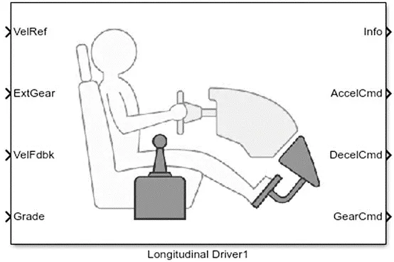
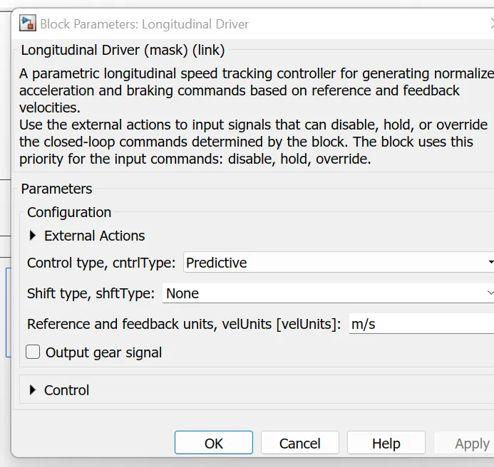
The Longitudinal Driver block acts as an actual driver who interprets the vehicle speed command from a reference signal. The block is capable of taking feedback velocity of the vehicle and changing the speed by giving output signals, it can decide when the vehicle needs to be accelerated and when the break needs to be applied.
Simulink-PS/ PS-Simulink Converter
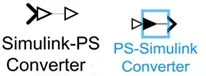
There are physical signals (PS) and Simulink Signal and we can’t use the Physical signals and Simulink signals interchangeably, thus require Simulink-PS Converter or PS-Simulink Converter depending on the input and output.
For eg. the acceleration command and velocity commands coming out from the driver block are Simulink signals which need to be converted into signal commands. For that, we utilize Simulink to PS converter.
Controlled Voltage Source
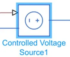
The Controlled Voltage Source block is used to give a constant voltage output. It has 2 electrical conserving ports and a physical signal port. The output from the controlled voltage source is fed to the controlled PWM voltage source.
Controlled PWM Voltage Source
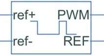
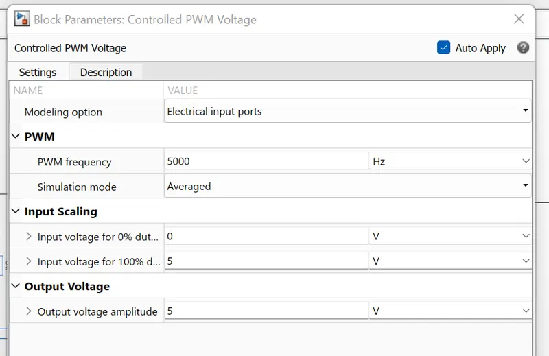
This block is used for providing a controlled PWM voltage output. The PWM signal is used for controlling the speed of the traction motor.
H-Bridge Motor Driver
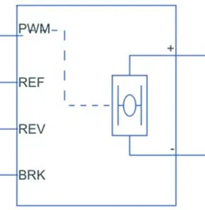
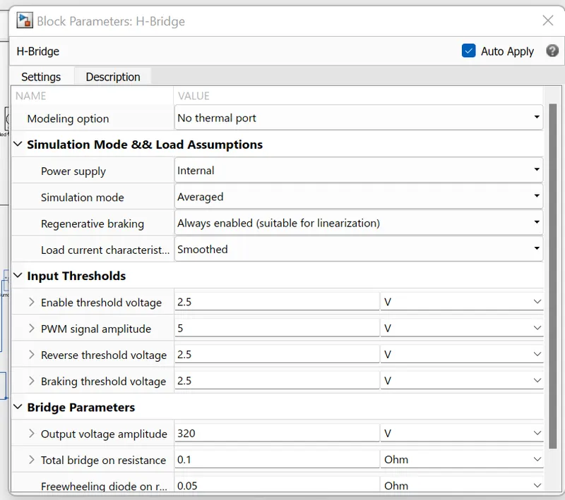
The H-bridge block is used to drive a motor. It has 2 modes an average mode where the block is used to apply an average voltage and the PWM mode where the motor is driven when the input voltage is above an enabled threshold voltage. The H-bridge block has 2 output ports, a positive and a negative port which is directly connected to the motor that has to be controlled. There is also a REV port. When the reverse threshold voltage is lower than the REV port voltage, the polarity of the motor is reversed, and if the BRK port voltage is greater than the value of breaking threshold voltage, it indicates that the vehicle is in breaking condition.
Motors
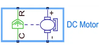
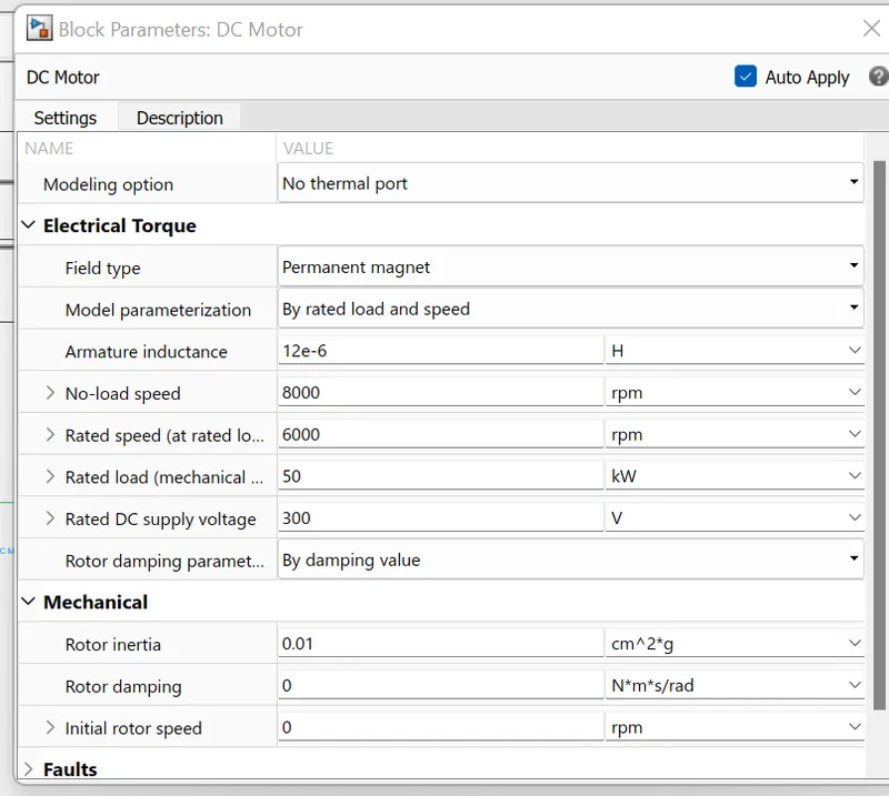
For traction motor, we are using a simple DC motor, but we can also use any other type of motor such as an Induction motor, PMSM, SRM, etc.
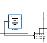
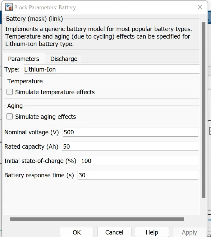
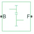
Battery: Lithium ion battery is used here, scope used with it shows state of charge and current .
Subsystem
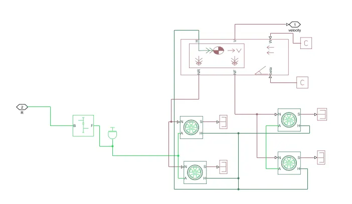
When working with bigger models, it is always a good idea to create a sub-system in order to declutter the whole model and to group components into a single block. You can easily create a subsystem by selecting the required components and pressing Ctrl+G or right-clicking on the selected blocks and then pressing on Create System from Selection from the drop-down menu which appears.
The EV model is a combination of both electrical and mechanical parts. The mechanical parts in the system include tires, vehicle body, transmission gears, and the motor. The 4 tires and the vehicle body are formed into a subsystem to separate the mechanical component from that of electrical components. The image of the subsystem is attached below.
The different components of our electric vehicle’s body, which let us feed physical forces experienced by the vehicle are used in the subsystem, the different blocks are explained below:
Vehicle Body :
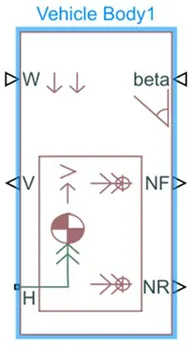
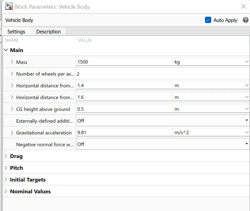
The vehicle body block represents a dual axel vehicle or a 4-wheeler. We can set parameters such as the weight distribution, mass, road incline, aerodynamic drag, etc. There are a total of 6 ports, W, V, H, NR, NF, and beta. The ports W and beta are physical signal input ports which are for wind speed and inclination of road respectively. Connections to V, NF, and NR are physical signal output ports for the velocity of the vehicle, Front axle, and rear axle normal forces and the H is for the horizontal motion and the tire is connected to this port.
Tire (Magic formula)
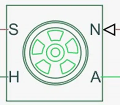
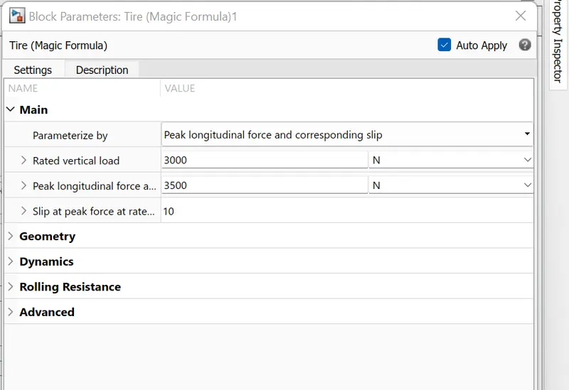
We have selected the tire(Magic formula). As can be seen in the sub-system, we have connected the hub of all 4 tires with the vehicle body’s hub. The tire (Magical Formula) is a tire block with longitudinal behavior. We are using it in a constant condition. We have connected the S with a terminator block, the S determines the slip of the tire. N is connected with the NR and NF ports of the vehicle block while the H, which is for the hub is connected to the H of the vehicle body. The A is the axel connection and is connected with the motor’s output shaft.
Terminator Block:
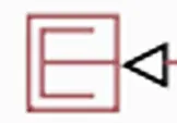
The terminator block is used to terminate a physical connection. It is a good practice to terminate any unused connection as it makes it clearer to understand and also terminates the port, hence, when a subsystem block is connected these ports are not visible on the sub-system.
PS-Constant Block :
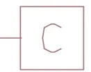
We can not use a regular constant block for providing physical signals, thus a physical signal block is used. This block is used for creating a physical signal constantly.
Simple Gear
This block is used for giving a fixed gear ratio. This is a mechanical component and can be avoided, but it gives users the ability to adjust vehicle speed wrt the rpm of the motor.
Testing and Simulation
After designing the circuit, all that is left is testing the circuit. We usually need to put scopes at any point in the circuit to measure the desired parameters. The scope module looks like the one shown below.
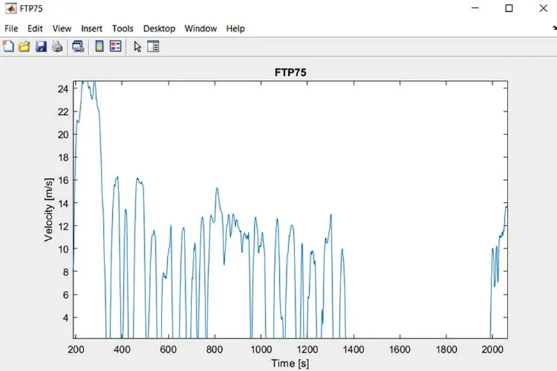
The scope can have multiple inputs, and the real-time output is displayed when the simulation starts. The drive cycle which is available in the default setting is an ftp75 which is a mandatory dynamometer test used as an industry standard. The high and low velocity makes it a good drive cycle to check the parameters of the drivetrain. The FTP75 drive cycle is shown below:
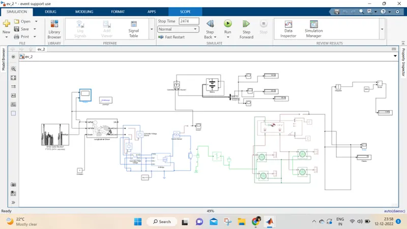
Model in simulink:
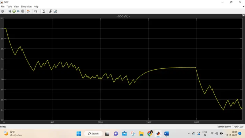
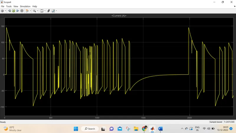
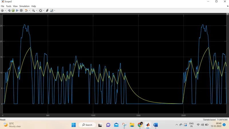
Conclusion: Using Simulink, an electric car model was created which uses a battery and a DC motor. The vehicle speed and the reference drive cycle were plotted and compared and the battery SOC state was observed for the entire duration. It has been observed that, The battery's state of charge for each drive cycle can be visualized from the SOC plot. As long as the vehicle is accelerating the SOC is decreasing but as soon as the deceleration starts, the SOC plot goes slightly up. This is because the battery is being charged, due to regenerative braking during deceleration.
REFERENCE:
- C. C. Chan and Y. S. Wong, "The State of the Art of Electric Vehicles Technology", Proceedings of the Power Electronics and Motion Control Conference, vol. 1, pp. 46-57, August 2004.
- S. Gupta and M. Patil, "A Hybrid Approach to Optimal Electric Drive Train Design", Third International Conference on Power Electronics Systems and Applications, May 2009.
- B. K. Powell, K. E. Bailey and S. R. Cikanek, "Dynamic Modeling and Control of Hybrid Electric Vehicle Power-Train Systems" in IEEE Control Systems Magazine, vol. 18, no. 5, pp. 17-33, October 1998.
- S. H. Kamble, T. V. Mathew and G. K. Sharma, "Development of Real-World Driving Cycle: Case Study of Pune India", Transportation Research Part D: Transport and Environment, vol. 14, no. 2, pp. 132-140, March 2009.