Final Project: Design of an Electric Vehicle
AIM: To create a MATLAB model of an electric car which uses a battery and a DC motor. And to prepare a report about the model including the following:
- System level configurations
- Model parameters
- Results
- Conclusion
INTRODUCTION:
An electric vehicle (EV) is a vehicle that uses one or more electric motors for propulsion. It can be powered by a collector system, with electricity from extravehicular sources, or it can be powered autonomously by a battery(sometimes charged by solar panels or by converting fuel to electricity using fuel cells or a generator).
As in other vehicles, the power of a vehicle's electric motor is measured in kilowatts (kW). 100 kW is roughly equal to 134 horsepower but electric motors can deliver their maximum torque over a wide RPM range. This means that the performance of a vehicle with a 100 kW electric motor exceeds that of a vehicle with a 100 kW internal combustion engine which can only deliver its maximum torque within a limited engine speed range. Energy is lost during the process of converting electrical energy to mechanical energy.
EVs first came into existence in the late 19th century, when electricity was among the preferred methods for motor vehicle propulsion, providing a level of comfort and ease of operation that could not be achieved by the gasoline cars of the time. Internal Combustion Engines were the dominant propulsion method for cars and trucks for about 100 years, but electric power remained commonplace in other vehicle types, such as trains and smaller vehicles of all types. Eventually, Electric Vehicles are taking a stance in the automobile markets starting with two-wheeler electric scooters to Electric powered planes.
In this report, I will be modelling an electric vehicle with a DC motor and battery system using the SIMULINK software. The model will run for a drive cycle and measure the velocity characteristics, current, and state of charge characteristics of the battery system. The components I need to include exist as blocks in the Simulink block library.
Types of EVs,
- Pure EVs
- Hybrid EVs
- Plug-in EVs
- Range extended EVs
- On and Off EVs
- Airborne EVs
- Seaborne EVs
COMPONENTS:
The main components of the Electric Vehicle are,
- Battery
- Motor controllers
- Motor/generator
- Power converters
- Transmission system
- Wheels/tires
Main simulation diagram:
In the following block diagram, the simulation of an electric vehicle is done using various drive cycles by using the powertrain blockset available in the Simulink library. Initially, the drive cycle is given as the input which provides the reference for the longitudinal driver which compares the two speeds and gives acceleration and braking commands to the motor controller block. Battery block and vehicle body blocks are further attached and scopes are used for displaying the working status.
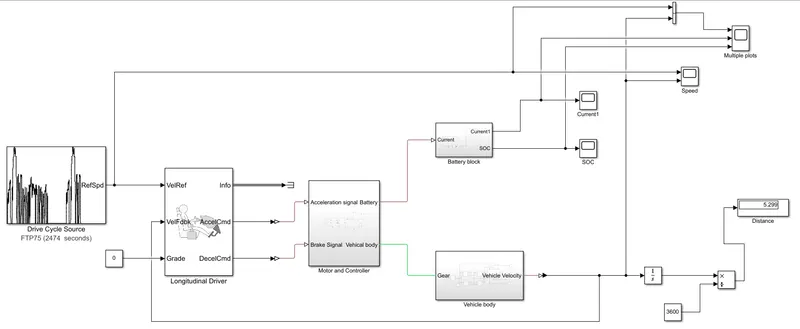
System level configuration:
For modelling the whole vehicle in SIMULINK, we need to model the above mentioned components separately and make them work together. All the main components are available in the library. So we add components and configure the parameters to fit the working requirements of the model.
DRIVE CYCLE DATA:
A drive cycle is a data set that contains velocity and time data for the purpose of modelling the motion of a vehicle. It is a plot of the vehicle velocity against the time and it is made to resemble typical driving conditions that a consumer may experience themselves. Drive cycles are used for various testing procedures such as mileage, pollution tests, and acceleration and top speed tests. There are different ways of implementing a drive cycle. One method is to create your own drive cycle with a spreadsheet. Another method is by issuing a signal builder and creating signals according to the user. In this model, I've used the FTP75 drive cycle.
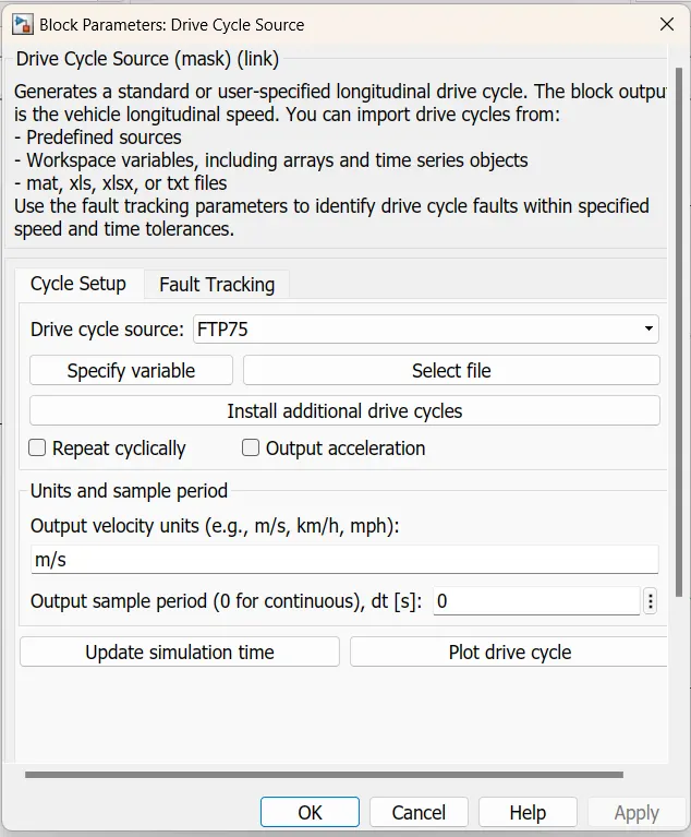
For this, we have used the Drive cycle source block.
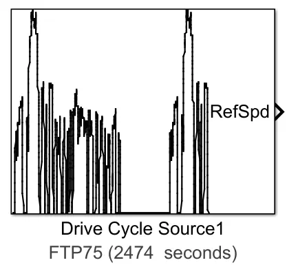
The block parameters for this block are as shown below,
LONGITUDINAL DRIVER:
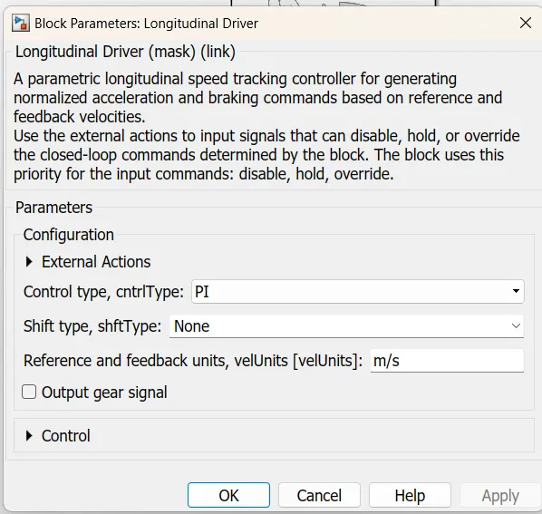
The longitudinal driver block is used for giving normalized acceleration and deacceleration commands to a controller based on two sets of data. The first data is the reference velocity and the second data is the feedback velocity. The reference velocity data comes from the drive cycle source and is compared to the feedback velocity data coming from the vehicle body. If the reference velocity is greater than the feedback velocity, an acceleration command will be given as an output to the controlled voltage source. If the reference velocity is lesser than the feedback velocity, a deceleration command is given as output to another control voltage source. We can use this block to model the dynamic response of a driver or to generate the commands necessary to track a longitudinal drive cycle.
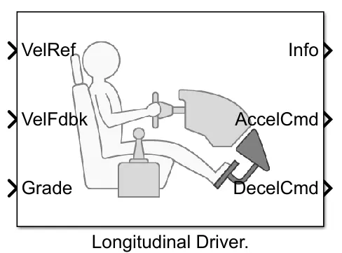
The ports in this block are:
- VelRef: This stands for the reference velocity and it is the velocity data provided from a drive cycle source.
- VelFdbk: This stands for feedback velocity and it is coming from the vehicle's body velocity port
- Grade: This port provides a grade or inclination angle on which the vehicle is travelling in degrees.
- Info: This port is for the bus signals which consists of block calculations
- AccelCmd: This port provides the acceleration command to a controlled voltage source
- DeceCcmd: This port provides the deacceleration command to another voltage source.
The block parameters for this block are as shown below,
MOTOR AND CONTROLLER SUBSYSTEM:
This subsystem has the blocks which are used to create the voltage signals to control the motor speed as per the input drive cycle data.
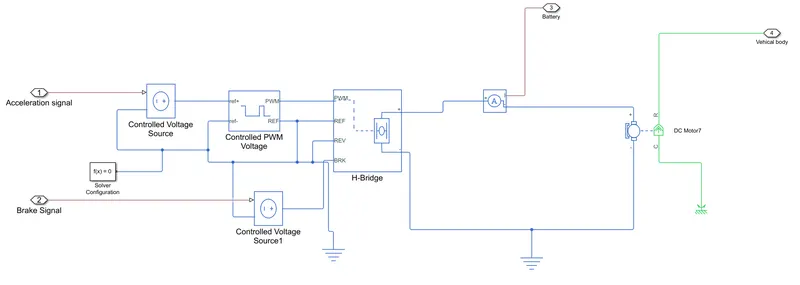
Components of this subsystem,
- Controlled voltage source
- Controlled PWM voltage
- H-bridge
- Current sensor
- DC motor
Controlled voltage source:
The block parameters are shown below,
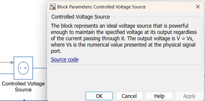
This block provides the necessary voltage that is powerful enough to maintain the voltage at the output regardless of the current that passes through it. In this subsystem, 2 control voltage blocks have been used. One block is used for acceleration and another to provide the voltage for deacceleration.
An electrical reference block is used to create a grounding effect for electrical circuits. It is used to create an electrical ground between a controlled voltage source, controlled PWM voltage, H-bridge blocks, and the electrical side of the DC motor. Also, mechanical rotational reference is used for the rotational side of the DC motor.
A solver configuration block is used to solve any necessary equations in a model.
Controlled PWM voltage:
The block and its parameters are as shown below,
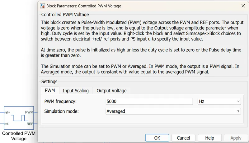
A 'controlled PWM voltage' is used to provide a controlled pulse width modulated voltage to the H-bridge block. The pulses of voltage created by this block are dependent on the duty cycle which is the ratio of the time that the switch is ON to the time taken for one cycle. The duty cycle formula is given by:-
Duty cycle= Ton/Ton +Toff= Ton /Tcyc. where Ton = On time,Tcyc=Time taken for one cycle.
`"Duty cycle"=(T_(on))/(T_(on)+T_(off))=(T_(on))/(T_("cycle"))`
where, `T_(on)` is the On time
and `T_("cycle")` is the time taken for one cycle
Electrical input ports: The block calculates the duty cycle based on the reference voltage across its "ref+" and "ref-" ports. This modelling variant is the default.
Here, the PWM frequency is set to 1000Hz. The simulation mode is set to "averaged" so that it will feed voltage pulses within quicker simulation times to the H-bridge. The remaining parameters of input scaling and output scaling are unchanged.
H-bridge:
The block and its parameters are as shown below,
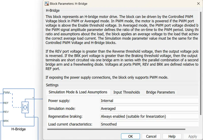
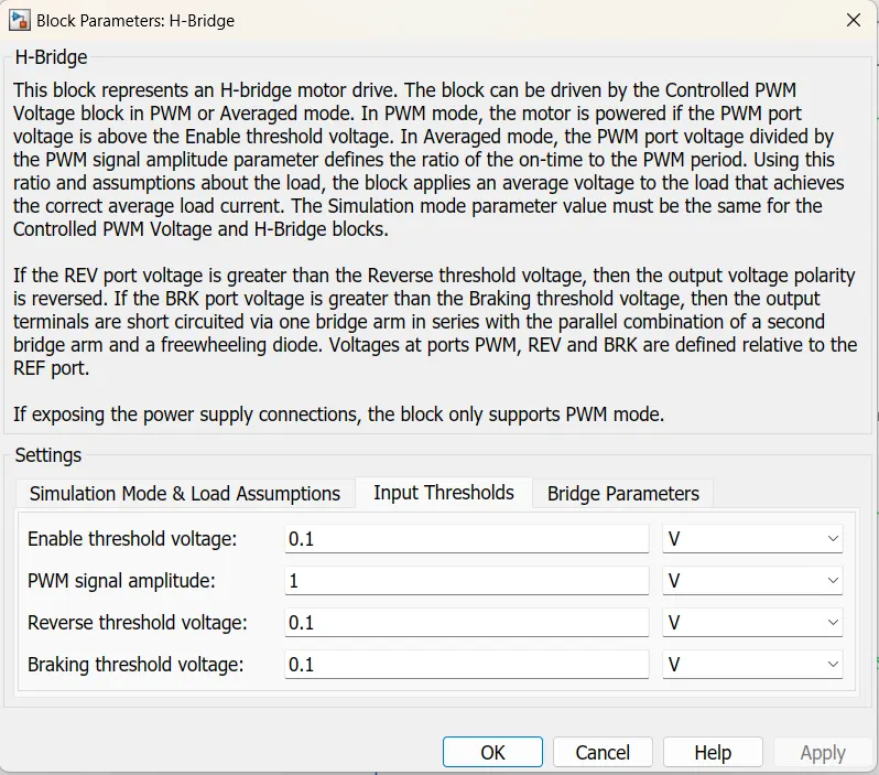
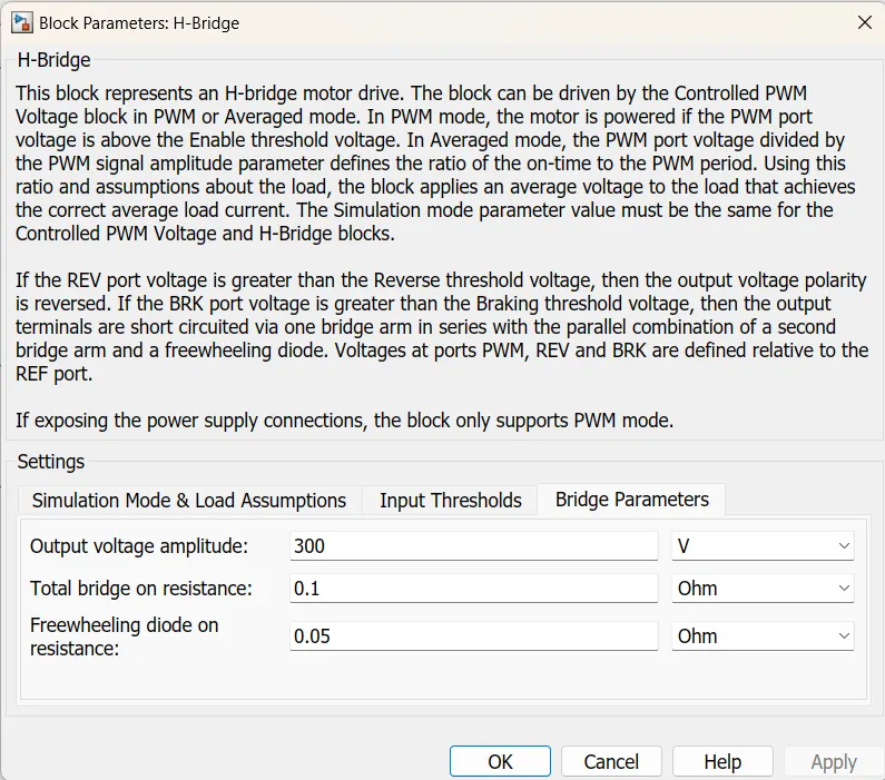
This is a power converter which is needed to provide the power of the correct form and magnitude from one component to other. In the case of EVs, a power converter is needed to provide a DC voltage from the battery of the EV to the DC motor, so that it can function properly at the required parameters. Here, H-bridge motor drive is used as the power converter. The left side is for controlling the voltage signals and the right side terminals provide the controlled voltage to the DC motor. The notations are as such below:
- PWM- Pulse width modulation
- REF- Reference
- REV- Reverse
- BRL- Brake
Current sensor:
The block and its parameters are shown below,
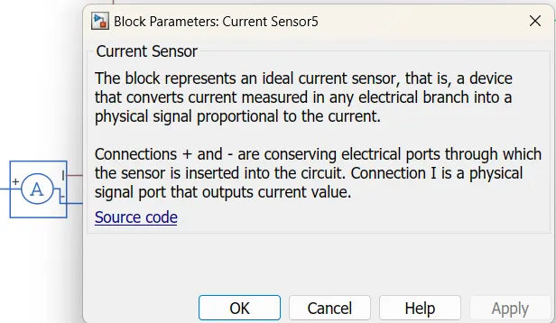
Here, this is used to measure the current flowing through the H-bridge.
DC motor:
The motor block and its parameters are shown below,
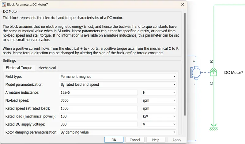
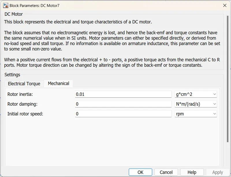
For the EV model, the DC motor block is selected because DC motors are easy to model and have very few parameters to run for a particular application. There are two sides of the block, the mechanical side is on the right and the electrical side is on the left. The mechanical side has two ports C and R, C stands for casing and is the stable part and R is the rotor which produces a torque. The electrical side has a positive and negative side for the voltages to be applied. If a positive voltage is applied to the motor block from the positive to the negative terminal then a positive torque will act from C to R port. The direction of the torque can be changed by changing the sign of the back emf or the torque constant. The C port is connected to the mechanical rotational reference because it will be stationary. The R port is connected to the gear in the vehicle body block.
Here I have chosen to parameterize the block by rated power, rates speed and no-load speed. This lets us modify the parameters such as DC supply voltage, and rated load. I have kept all values default except for the no-load speed, rated speed and rated load.
BATTERY SUBSYSTEM:
This subsystem has the blocks which are used to charge, discharge, and estimate the State of Charge of the battery.
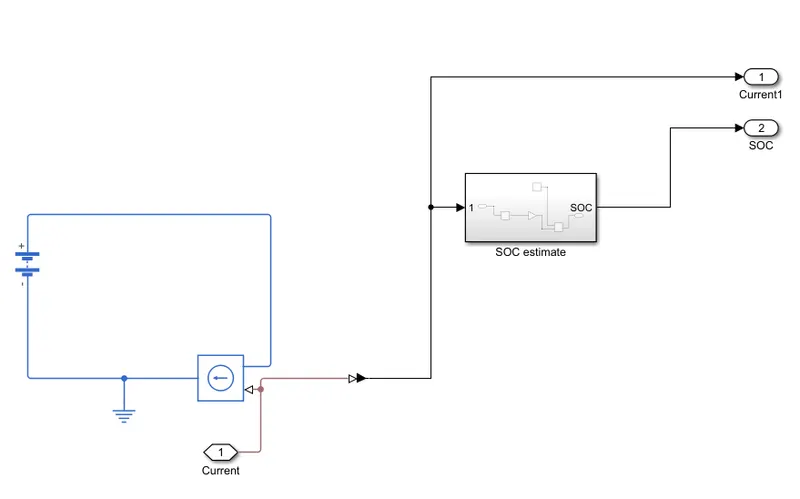
Components of this subsystem:
- Battery
- Controlled current source
- State of Charge(SOC) estimate subsystem
Battery:
This battery block represents a simple battery model. The block models the battery as a series of internal resistance and a constant voltage source. The battery will be the energy store of the EV and will contain the electrical energy in DC form and provide this energy to operate.
The block and its parameters are shown below,
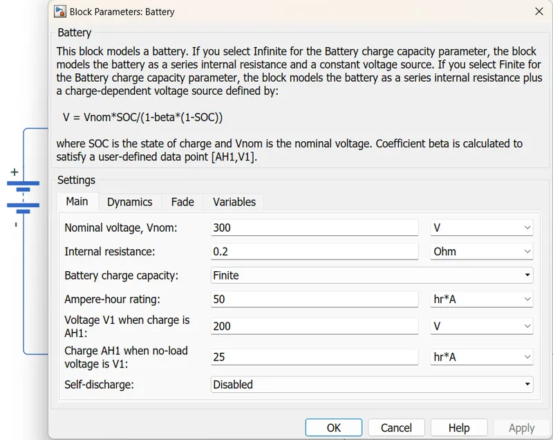
The nominal voltage has been set to 300 volts, internal resistance has been set to 0.2 ohms and a finite charging capacity. All other parameters are default.
Controlled current source:
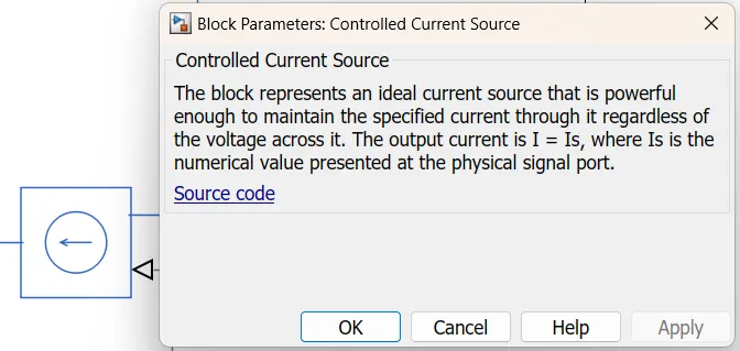
This block is a part of the battery sub-system. Similar to a voltage source, this block produces an ideal current that is powerful enough to maintain the specified current regardless of the voltage across it.
The block and its parameters are shown below,
State of Charge(SOC) estimate subsystem:
This subsystem is used to measure the State of Charge of the battery.
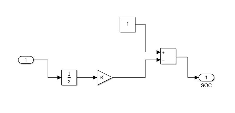
Components of this subsystem:
- Integrator
- Gain
- Add
The first block is the integrator block used to handle data transfer and integrate the value of the current signal with respect to time and next is the gain block used in order to multiply and divide the signal coming from the integrator block. This block will divide the current signal with the ampere rating of the battery which is 140(Ah)*3600(secs). Assuming the battery is always fully charged the constant block is added with a value of 1 representing 100%. Next, a sum block is used to perform addition and subtraction operations. These blocks are made into a subsystem called SOC estimate.
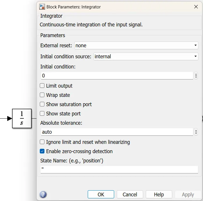
Block parameters of Integrator block:
The input for this block is from a current sensor. This block is used to handle data transfer and integrate the value of the current signal with respect to time.
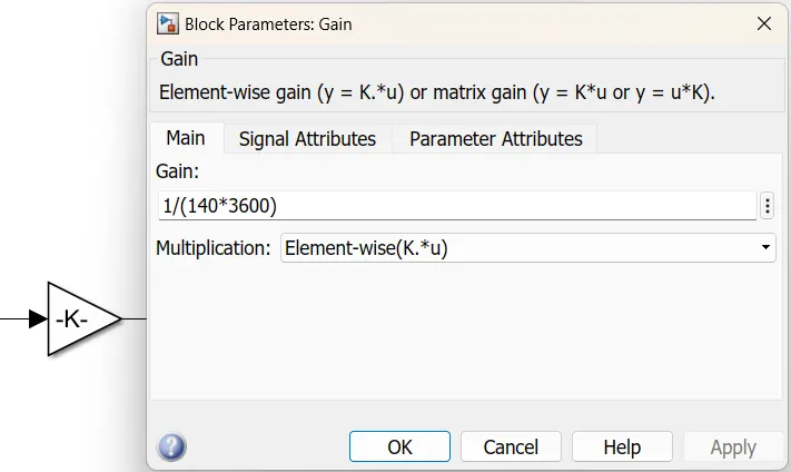
Block parameters of the Gain block:
The gain block is used to multiply and divide the signal coming from the integrator block. This block will divide the current signal with the ampere rating of the battery which is 140(Ah)*3600(secs).
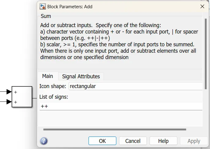
Block parameters of Add block:
The input for this block is from the gain block and constant(here, 1). This block is used to perform addition and subtraction operations.
VEHICLE BODY SUBSYSTEM:
This subsystem represents the body of a vehicle. The input for this subsystem comes from the DC motor from Motor and Controller block.
The block diagram for this subsystem is shown below,
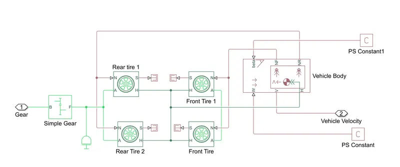
The above blocks form a subsystem which serves as a part of the whole vehicle. Four tires are connected, where the right two tires are the front wheels and the remaining two are the rear wheels. They are interconnected to the hub of the vehicle body block. And their respective axles are connected accordingly. The rear axle is connected with the gear as we want the model to be a rear-wheel drive vehicle. Here the wind velocity port and hill-climbing angle ports are connected to physical constant blocks which are kept as zero.
Components of this subsystem:
- Vehicle body
- Simple gear
- Inertia
- Tire(magic formula)
Vehicle body:
The block and its parameters are shown below,
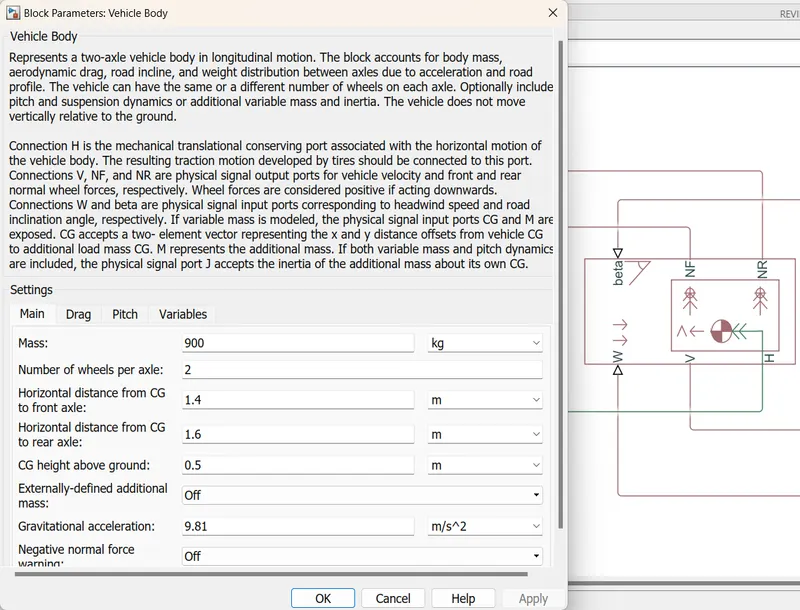
This block contains 6 ports which can be used to model various aspects of the vehicle body. The ports are mentioned below;
- H: This stands for hub and is used to connect the hubs of the wheels to the main body of the vehicle.
- V: Physical signal output port which stands for 'Velocity' and is used for the output velocity of the vehicle.
- W: Physical signal input port and allows us to model a Wind velocity that acts against the vehicle.
- NR: Physical signal output port to connect the rear wheels of the vehicle.
- NF: Physical signal output port to connect the front wheels of the vehicle.
- Beta: Physical signal input port which allows the vehicle to undergo an inclination of hill climbing force.
Simple gear:
The block and its parameters are shown below,
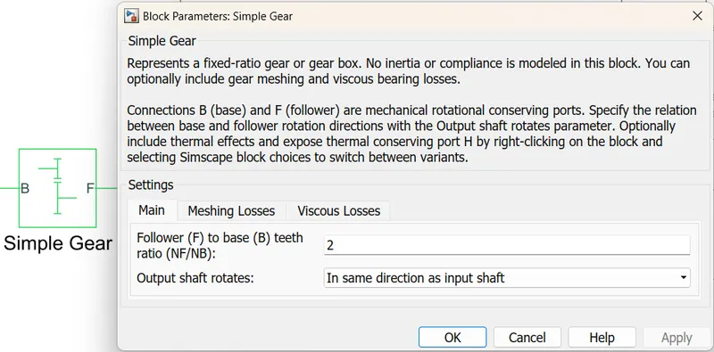
This block is used to model a gear system with a fixed gear ratio with no inertia effects. However, we can modify the meshing of the gear teeth. Here, the follower-to-base teeth ratio has been set to 2 and the output shaft rotates in the same direction as the input shaft.
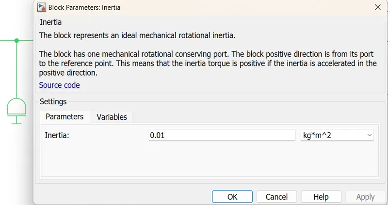
Inertia:
The inertia acting on the shafts is given using an Inertia block. This block and its parameters are shown below,
Tire(magic formula):
Now the simple gear is connected to all four wheels, representing an all-wheel drive vehicle. The tires are represented using a tire (magic formula) block. This block and its parameters are shown below,
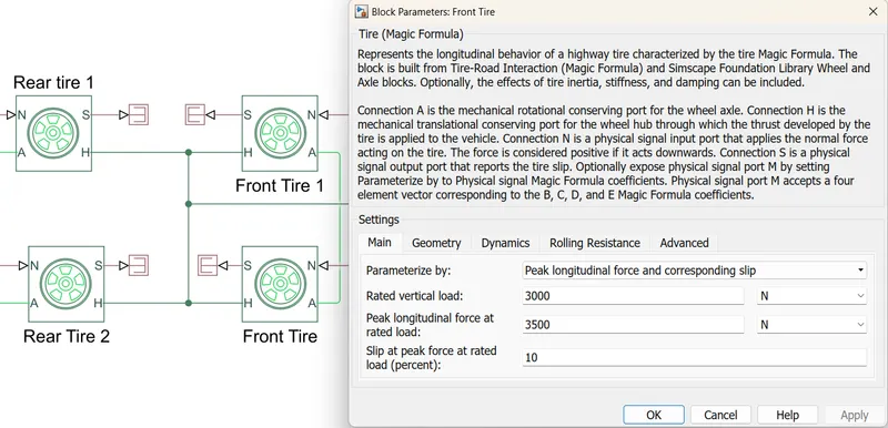
Here, we can also change the geometry, dynamics, rolling resistance, and other characteristics as we want.
SPEED MEASUREMENT:
In order to measure the speed, the scope block is modified to have two input ports, one of which accepts the output velocity signal from the vehicle sub-system block and the other of which accepts the output signal from the drive cycle to the reference velocity port on the longitudinal driver block. This was done to compare the two speeds and see if they coincided with one another and achieved the same speed.
DISTANCE MEASUREMENT:
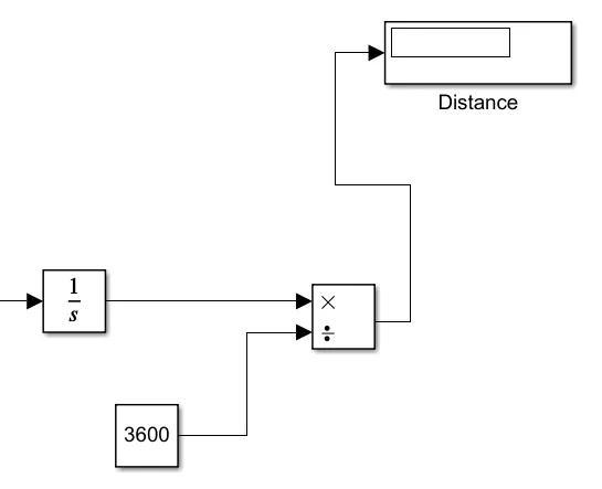
The distance travelled by the vehicle is measured using mathematical blocks. First, the integrator block is implemented to integrate the velocity signal that is output from the velocity sub-system. A divider block along with a constant block having a value of 3600 is used to divide the integrated speed. This will give us the distance travelled in kilometres.
RESULTS:
The program is made to run with an FTP75 drive cycle and the outputs from speed, current and SOC scopes are recorded. The distance travelled by the vehicle in the drive cycle is also measured and displayed using the display block. The run time is set to 2474 secs according to the drive cycle time.
Speed scope:
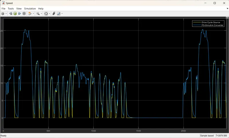
This scope depicts speed with respect to time according to the drive cycle. From this scope, we can see two signals. The blue signal represents the vehicle body speed and the yellow signal is the FTP75 drive cycle data. We can also see that the longitudinal driver tries to maintain the speed according to the drive cycle data. The graph overlaps each other effectively during acceleration and deceleration. Only when the speed suddenly drops to 0 in the FTP75 drive cycle, the model takes time to catch up. On all other occasions, the model traced the drive cycle closely.
Current scope:
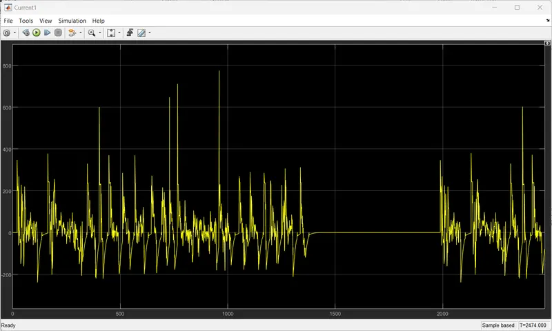
This scope depicts the current flowing from the battery to the motor with respect to time. From this scope, we can clearly observe that during deceleration there is regeneration of current and recharges the battery. We can observe that the maximum current value during normal driving is around 780A and during regenerative braking the maximum current value reached is near to 220A.
State of Charge(SOC) scope:
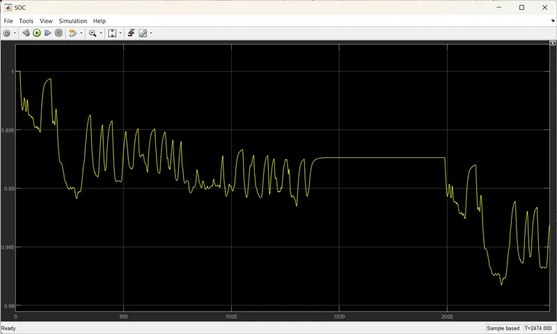
This scope shows how the state of the battery varies over the drive cycle time. The battery was modelled to begin with a SOC of 1 which is 100%. As the simulation starts the charge of the battery starts to decrease and also we can see sudden spikes in that graph, these spikes represent the regenerative braking region. During this, the SOC value increases. Here we can see that after the whole simulation, the State of Charge of the battery is just at 98.5% after a drive cycle time of 2474 secs.
Multiple plots:
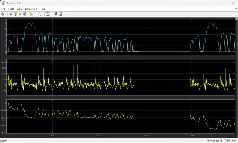
This scope is just to illustrate the corresponding values of each plot
Distance travelled:
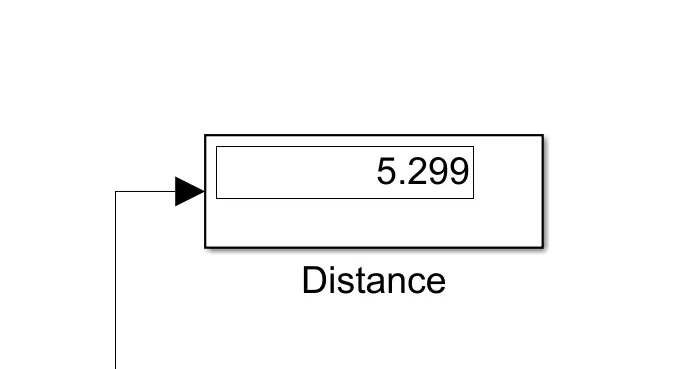
From the above image, the display block measured the distance as 5.299 km in 2474 secs and with a charge of 98.5% remaining in the battery.
CONCLUSION:
The MATLAB model of an electric car which uses a battery and a DC motor has been successfully made by choosing suitable blocks from the Powertrain block set.