Final Project: Design of an Electric Vehicle
FINAL PROJECT= DESIGN OF AN ELECTRIC VEHICLE.
AIM= To create a MATLAB model of electric car which uses a battery and a DC motor.choose suitable blocks from powertrain block set and prapare a report about your model including following points:
Objectives:
1) System level configurations
2) Model parameters
3) Results
4) Conclusion.
Answer=
the electric car is a vehicle which is partially or fully propelled by an electric motors,using a energy stored in rechargeable batteries.
- the electric cars were invented practically in the 1880s but it was popular late in the 19th century and early 20th century.
-at that time ,the innovation and advanced growth of the internal combustion engines (ICE) and mass production of cheaper gasoline vehicles has led to decline for the use of electric vehicles.
-as per user choice,there are various types of electric cars changed,developed and innovated time to time.
- as of now,the world is very much familiar with the terms BEV,HEV,PHEV and FCEV.
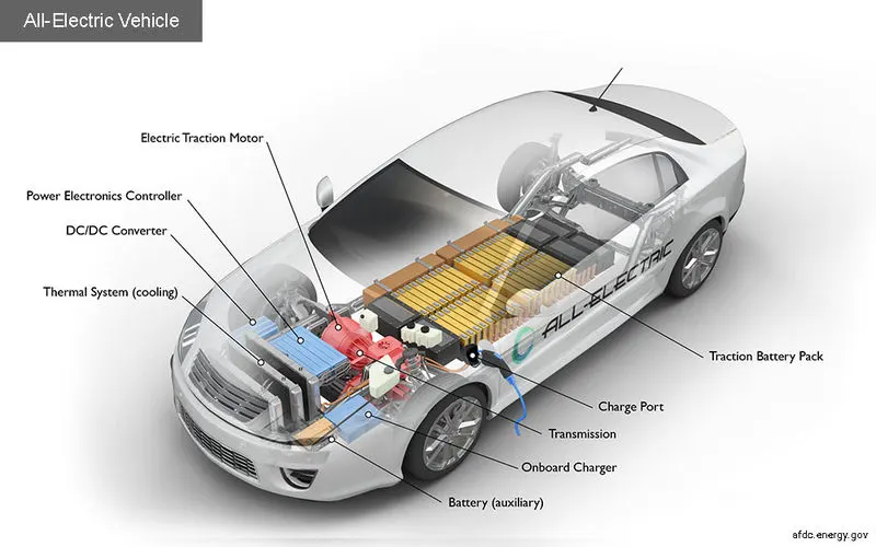
In genral electric car working=
- if we press the pedal of the car then controller takes action and regulates the electrical energy from the batteries and inverters as per requirement.
- when the controller seting has been done then the inverter sends a certain amount of electrical energy to the motor ( as per the depth of pressure on the pedal).
-then the electric motor converts electrical energy into mechanical energy and motor rotor rotates the transmission therefore the wheels of the vehicle rotated which results the car moves .
types of electric vehicle =
1) Battery electric vehicle (BEV)
2) Hybrid electric vehicle (HEV)
3) Plug-in hybrid electric vehicle (PHEV)
4) Fuel cell elctric vehicle (FCEV)
1) Battery electric vehicle (BEV) =
- it is entirely runs on a battery and electric drive train.
- in this types of electric car/vehicle we do not use ICE,so energy is stored in a large battery pack through charged by plugging into electricity grid.
- the energy stored in the battery used to power the one or more electric motors to run the electric car.
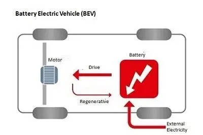
- the main components used in BEV are electric motor,inverter,battery,control module and drive train.
-inverter converts power from DC battery to AC for the electric motor.
- when the accelerator padal send a signal to the controller then adjusts the vehicle speed by changing the frequency of the AC power from the inverter to the motor.
-then rotated rotor turns the wheels through transmission.
-when the brakes are pressed as per requirement then the electric car is decelerating,the motor become goes to alternator mode and produces power which is sent back to the battery.
the example of this type of vehicle is Volkswagen e-Golf,Tesla model 3,BMW i3,chevy spark,Nissan LEAF,Ford Focus Electric,Hyundai Ioniq,Karma Revera etc.
2) Hybrid electric vehicle (HEV)
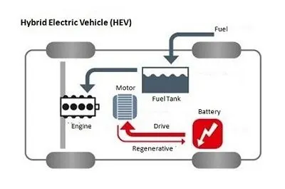
- it is also called as standard hybrid or parallel hybrid electric vehicle.
-in this vehicle,we use both an ICE and an electric motor.
- in this types of electric cars , for internal combustion engine getting energy from fuel and for the electric motor getting electricity from batteries.
-both gasoline engine and electric motor works simultaneously to rotate the transmission of the vehicle ,which drives the wheels.
-the main differance between HEV as compared with BEV and PHEV is the batteries in HEV can be charged by the ICE or motion of the wheel or a combination of both.
-in this car,there is no chraging port therefore the battery can not be recharged from outside of the system.
-the components of HEV are engine,electric motor,battery pack with controller and inverter,fuel tank,control module.
-it has a fuel tank that supplies gas to the engine like a regular car and also it has a set of batteries that run the electric motor.both the engine and electric motor can turn the transmision at the same time to move the vehicle.
-the examples of this vehicle is Honda civic hybrid,toyots prius hybrid,honda civic hybrid,toyota camry hybrid.
3) Plug-in hybrid electric vehicle (PHEV)=
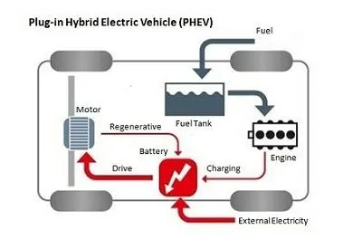
-it is a type of hybrid that both an ICE and a motor,also called as series hybrid electric vehicle.for this type of electric cars there is a choice of fuels.
-this type of electric vehicle is powered by a conventional fuel (gasoline) or an alternative fuel (bio-diesel) and also a rechargeable battery pack.
-the battery of the vehicle can be charged up with electricity by plugging into an electrical outlet or electric vehicle charging stations(EVCS).
-this vehicle typically run at least two modes-
- all electric mode-in this, battery provide the energy to the motor to move the vehicle and also for other accesories.
- Hybrid mode- in this,both electricity and gasoline are employed.
- the component of PHEV are electric motor,engine,inverter,battery,fuel tank,control module,battery charger(if onboard model).
- it is typically start up in all electric mode and operate on electricity untill their is a battery pack depleted.
- there is some model-shift to hybrid mode occurs when they reach highway cruising speed,generally above 60-70 miles per hour.
-whenever the battery is empty,the engine takes over that is engine start and the vehicle can be operates as a conventional ,non-plug-in hybrid.
- in addition to plugging into an outside electric power source,PHEV betteries can be charged by an combustion engine or regenerative braking.
- at the time of braking,the electric motor acts as a generator and this generating energy is used to charge the battery.
-in this,the electric motor is a supplements the engines power as a results smaller engines can be used,increasing the cars fuel efficiency without compromising performance.
the examples of PHEV is Porsche cayenna SE-hybrid,Chevy vott,Chrysler pacifica,Ford c-max energi,Ford fusion energi,Mercedes C350e,Mercedes S550e etc.
4) Fuel cell elctric vehicle (FCEV)=
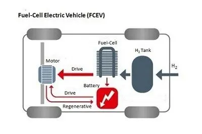
- it is also known as fuel cell vehicles(FCVs) or zero emmision vehicle,are the types of electric cars that employ fuel cell technology to generate the electricity required to run the vehicle.
-in this type of vehicles,the chemical energy of the fuel is converted directly to electric energy.
- the components of FCEV are electric motor,fuel cell stack,hydrogen storage tank,battery with converter and controller.
- the fuel cell electric car working principle is different compared to that of a plug-in electric car.
-the Fuel cell generates the electricity required to run this vehicle on the vehicle itself .
-the examples of FCEV are Toyota Mirai, Hyundai Tuscon FCev,Riversimple rasa,Honda clarity fuel cell,Huyndai Nexa.
ELECTRIC CAR COMPONENTS-
-Electric car or vehicle component and function depend on the car type.
-Here we discuss various common main electric vehicle/car components or parts or elements and their function such as traction batteries,inverters (DC-DC converters),traction motors,on-board chargers and controllers.
-the different electric cars (vehicles) components and functions are as follows-
a) Traction battery pack-
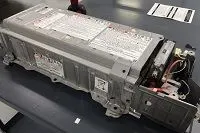
-the main function of the battery in the electric vehicle is to store electrical energy in the form of direct-current electricity(DC).
-the controller sends a signal to the battery,then the battery will flow the DC electrical energy to the inverter to then be used to drive the motor.
- the type of battery used is a rechargeable battery and which is arranged in such a way that of traction battery pack.
- currently there are different types of electric car batteries used but the most widely used battery is lithium-ion batteries.
b) power inverters-
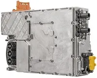
-the direct current (DC) of the battery is converted in to an alternating current (AC) with the help of inverter and this alternating current is used in the electric motor.
-during regenerative braking ,the inverter on an electric car has a function to change the AC current to DC current and then it is used to recharge the battery.
- this type of inverter used in some electric car models is the bi-directional inverter category.
c) Controller=
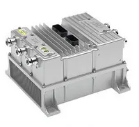
-the function of the controller is as a regulator of electrical energy from batteries and inverters that will be distributed to electric motors.
-the input of the controller is the car pedal which is set by the driver.
-the setting of the pedal determines the frequency variation or voltage variation that will enter the motor and at the same time determines the cars speed.
-in genral ,this unit is used to control the flow of electrical energy delivered by the traction battery,also controlling the speed of the electric traction motor and the torque produced.the working of electric car is mainly depend on this component.
d) electric traction motor-
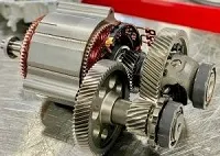
-the controller provides electrical power from the traction battery,the electric traction motors turns the transmission and then moves the wheels.
- in some hybrid electric cars ,we can use a type of generator -motor that performs both the operation like propulsion and regeneration.
-in genral,the type of electric motor used is the BLDC (brushless DC) motor.
e) Charger-
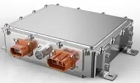
-this is a battery charging device.
-the chargers get electricity from outside sources,such as the utility grid or solar power plants.
-chargers converts AC electricity into DC electricity and stored in the battery.
-there are 2 types of electric car chargers:
- On-board charger: this type of charger is located and installed in the car.
- Off- board charger: this charger is not installed or not located in the car.
f) transmission-
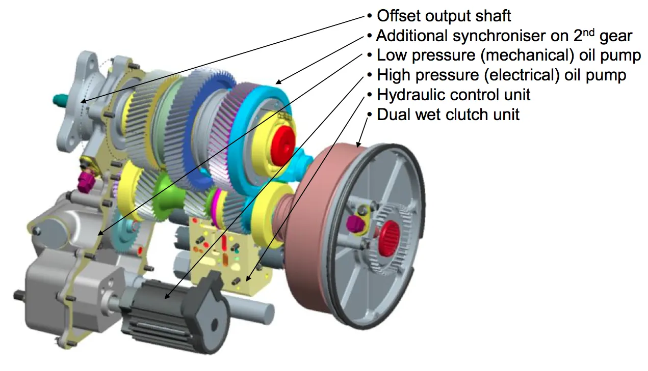
it transfers mechanical power from the electric traction motor to drive the wheels.
g) DC-DC converter=
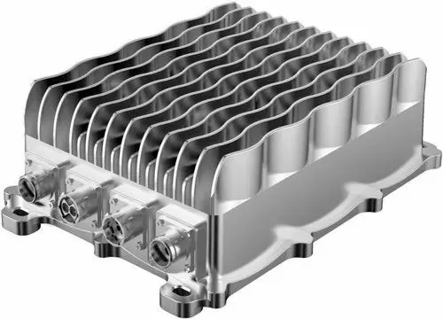
the main function of this device is to converts higher-voltage DC power from the traction battery pack to the lower-voltage DC power required to run the vehicle or to run other accessories and to recharge the auxillary battery.
h) Thermal system=
- this system maintains a proper operating temperature range of the engine,electric motor,power electronic devices and all other components.
i) Charge port-
the charge port allows the vehicle to connect an external power supply in order to charge the traction battery pack.
MODELLING OF EV
objectives-
- electric vehicle with fever components.
- to make a most simple and low run time vehicle model using individual component models.
- to checkout performance parameters speed,SOC,current etc with various drive cycles.
- to play with motor power,vehicle body (rolling resistance,air drag,weight)inputs.
- to know MATLAB models and their configuration to match with actual vehicle.
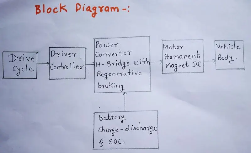
this block diagram is a schematic general arrangement of the principle parts of an electric car and it is reference to the our MATLAB model of an electric car.in this shows there are 6 main parts of this arrangement. the electric vehicle has vehicle body,DC motor,power converter,driver controller ,drive cycle and battery.in this ,the drive cycle is used to input the data into the driver controller.the driver controller controls the acceleration and decceleration of the vehicle.power converter which is a H-bridge with regenerative braking,here we use H-bridge to drive the DC motor.as per our model we are using a battery and dc motor. battery can not directly connected to motor because if we connect then rated voltage is given to motor and motor speed is also rated ,we can not increase or decrease motor speed variation as per our requirement of vehicle.the motor block and battery block is connected to the power converter block so power converter plays a vital role in the controlling and converting the electrical energy.so where the battery block indicates the charge and discharging condition and % SOC (state of charge) variations with respect to the drive cycle.motor blocks indicates we are using which type of motor and its positioning,here we are using the permanent magnet DC motor and finally the vehicle body block indicates the mechanical structure of an electric car like wheels and their connections.then the motor rotational energy rotates the wheel throght transmission gear system.
simulink model
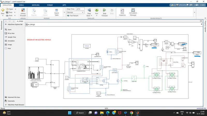
now we will discuss each blocks used in this simulink model-
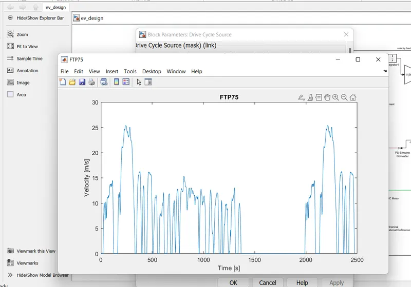
1) drive cycle source-
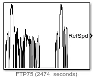
this block helps in inputting the drive cycle data ,whether it is built in or custom made by the user.
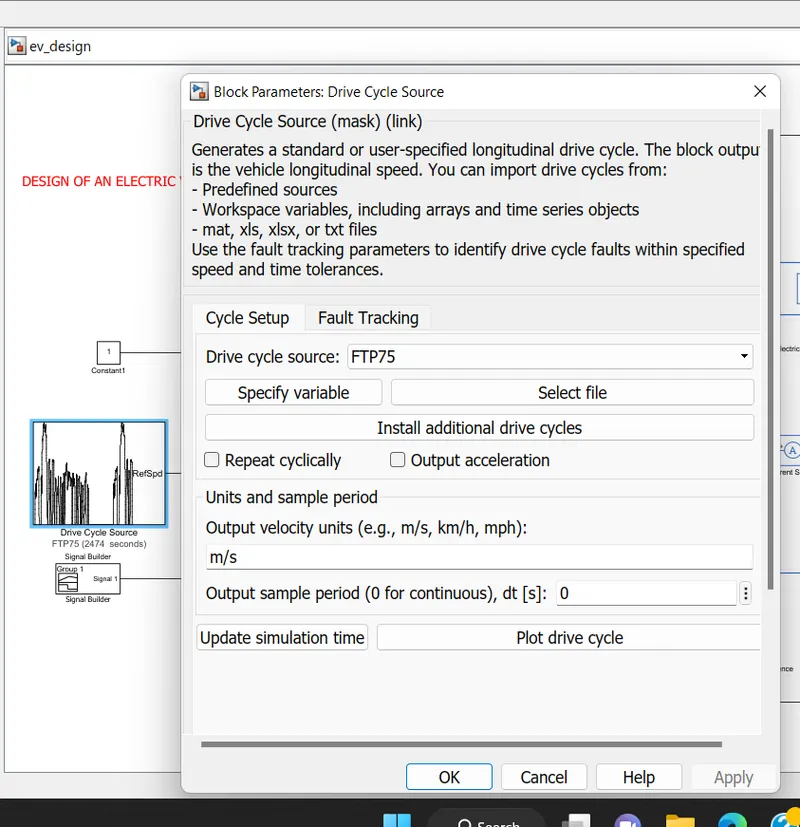
we also use the drive cycle data in excel sheet using this block.here we used FTP75 drive cycle.
for the operation of the cycle ,the test duration would be 2474 seconds.
the block parameters for this drive cycle block is-
the drive cycle plot is
2) Longitudinal driver-
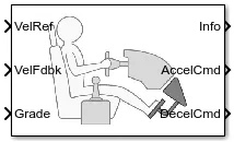
the longitudinal driver block implements a longitudinal speed-tracking controller.
based on reference and feedback velocities,this block generates normalized acceleration and braking commands that can vary from 0 through 1.
we can use the block to model the dynamic response of a driver or to generate the commands necessary to track a longitudinal drive cycle.
velocity reference - drive cycle.
velocity feedback- connected to vehicle body speed calculation and it acts as a close loop feedback to meet the desire speed as per reference input.
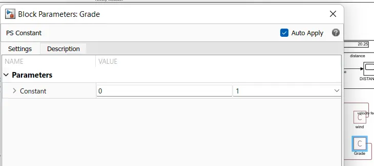
grade - which is constant zero assumed
info terminal -not connected
acceleration command- this terminal connected to PWM source throgh which it is connected to controlled PWM voltage to vary the duty cycle according to drivers input
deceleration command- it is connected to braking of H-bridge to maintain the speed according to the drive cycle and deccelerate the vehicle.
the block parameters are as shown below-
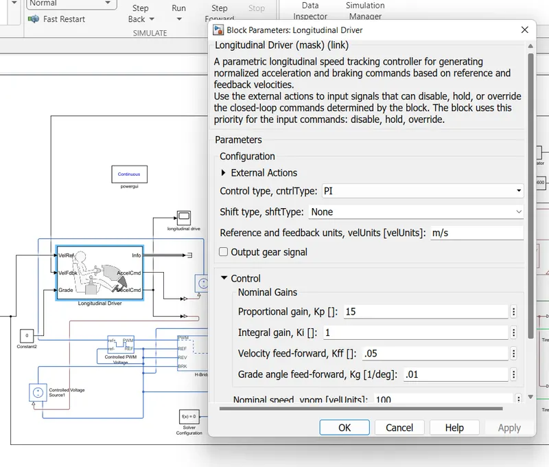
PI control is selected for this block, this is nouthing but throttle pedal of the driver which will try to match with the input drive cycle given and according to it PI controller will try to match whether acceleration or decceleration as per input given.
3) controlled PWM voltage block -
- this block is used to create the pulse width modulated (PWM) voltage.
- electrical input ports- this block calculates the duty cycle which is based on the reference voltage across its ref+ and ref- ports.this modelling variant is the default.
-the value of the output voltage amplitude parameter determines amplitude of the output voltage.
ref + = reference positive connected with the acceleration commands from the driver model
ref- = reference negative connected with the deceleration commands from the driver model
PWM = PWM connected directly to the H-block.
REF = REF connected directly to the H-block
- the parameters of this block is as
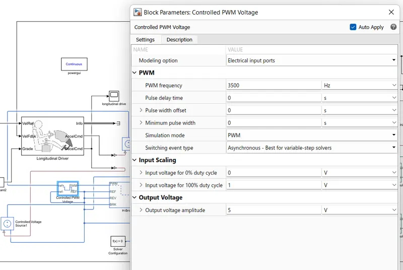
-here for simulation, we considered the PWM simulation mode .
-for input scalling we considered 1 V for 100 % duty cycle.
- maximum output is 5 V (Amplitude).
4) H- bridge=
-this block is used to change the polarity of the voltage applied across the DC motor so as to run the motor in forward and reverse direction as per the input command.
-this block is driven by controlled PWM voltage block in PWM or averaged mode.
- in PWM mode,the motor is powered if the PWM port voltage is above the enable thresold voltage, in averaged mode,the PWM port voltage divided by the PWM signal amplitude parameters defines the ratio of the on-time to PWM period.
- using the ratio assumptions about the load,the block applies an average voltage to the load that achieves the correct average load current.
- the simulation mode parameter must be same for the controlled PWM voltage and H-bridge blocks.
-REF- controlling with reference
-REV -controlling with reverse
-BRK- controlling the brake and regenerative action
+ = controlled output to the positive terminal of the motor
- = controlled output to the negative terminal of the motor
-the block parameters of H-bridge is as
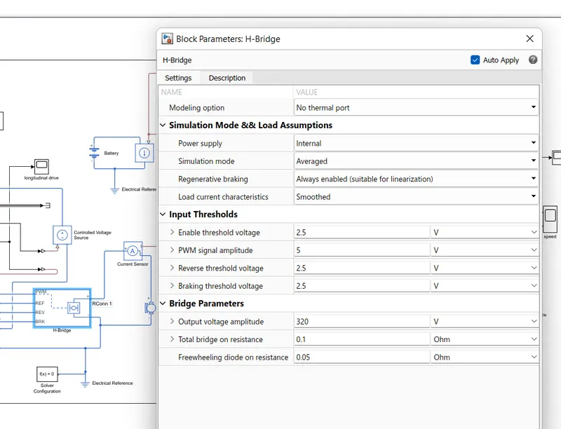
we have selected the internal type power supply and enabled the regenerative braking for flow power back to battery while braking and decceleration to make EV efficient.
the following values are considered for H-bridge-
- output voltage amplitude-320
- enable threshold voltage-2.5 V
- PWM signal amplitude-5V
- reverse threshold voltage-2.5V
- braking threshold voltage-2.5V
5) gear box-
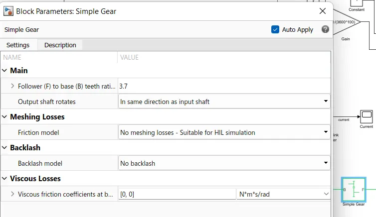
- the gear box block represents an ideal ,nonplanetary ,fixed gear ratio gear box.
- the gear ratio is determined as the ratio of the input shaft angular velocity to that of the output shaft.
- the parameters of gear box block as-
6) DC motor-
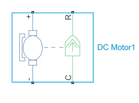
- using the power from the battery pack this motor drives the vehicle wheels.
- some vehicles use the motor generators to perform both the drive and regeneration functions.
-this is the DC motor (Brushed type) terminals are connected as -
+ = electrical signal to the motor positive terminals
- = electrical signal to the motor negative terminals
C = connected to casing of the motor connected with the mechanical rotational reference block.
R = rotor shaft of dc motor is connected to simple gear ,which vary torque and speed.
- the parameters of dc motor are
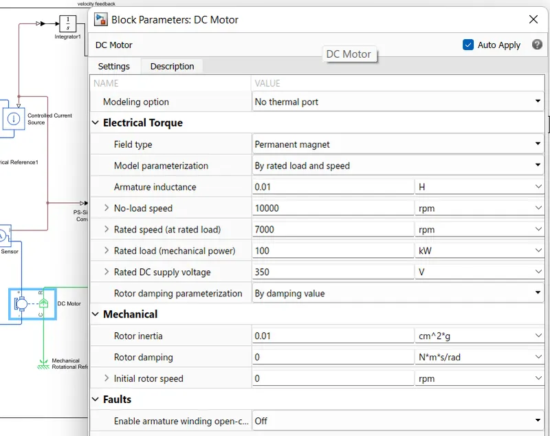
the parameters values are as follows-
- rotor inertia -0.01
- field type - permanant magnet
- no-load speed-10000 rpm
- rated speed (at rated load)-7000 rpm
- rated load- 100 Kw
- rated DC supply-350 V
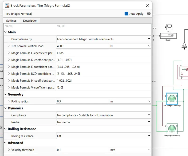
7) tire/wheels=
- this block represents the longitudinal behaviour of a highway tire characterized by the tire magic formula .
- connection A is the mechanical rotational conserving port for the wheel axle.
- connection H is the mechanical translational conserving port for the wheel hub through which the thrust developed by the tire is applied to the vehicle.
- connection N is the physical signal input port that applies the normal force actine on the tire.
- connection S is a physical signal output port that reports the tire slip.
- the parameters for tire block are
8) Vehicle body-
- the vehicle body block represents a two axle vehicle body in longitudinal motion.
- the vehicle has the same or different number of wheels on each axle.for example ,two wheels on the front axle and one wheel on the rear axle.each vehicle wheels are of same size and structure.
-this block accounts for body mass,aerodynamic drag,road incline and weight distribution between axles due to acceleration and road profile.
- optionally include pitch and suspension dynamics,the vehicle does not move vertically relative to the ground.
-this block has an option to include an externally defined mass and an externally defined inertia.
-the mass ,inertia and centre of gravity of the vehicle body can vary over the course of simulation in response to system changes.
- angle terminal (beta)= the angle is the slope in the road condition at which the car is running.
- wind= it is specified as per the condition where the vehicle has to be driven.
- Velocity = the speed of the EV car.
-H = it is a conserving port associated with the horizontal motion of the vehicle body. tire traction motion is connected to this port.
- NF= the front wheel connection
- NR= the rear wheel connection.
-the parameters of vehical body block is
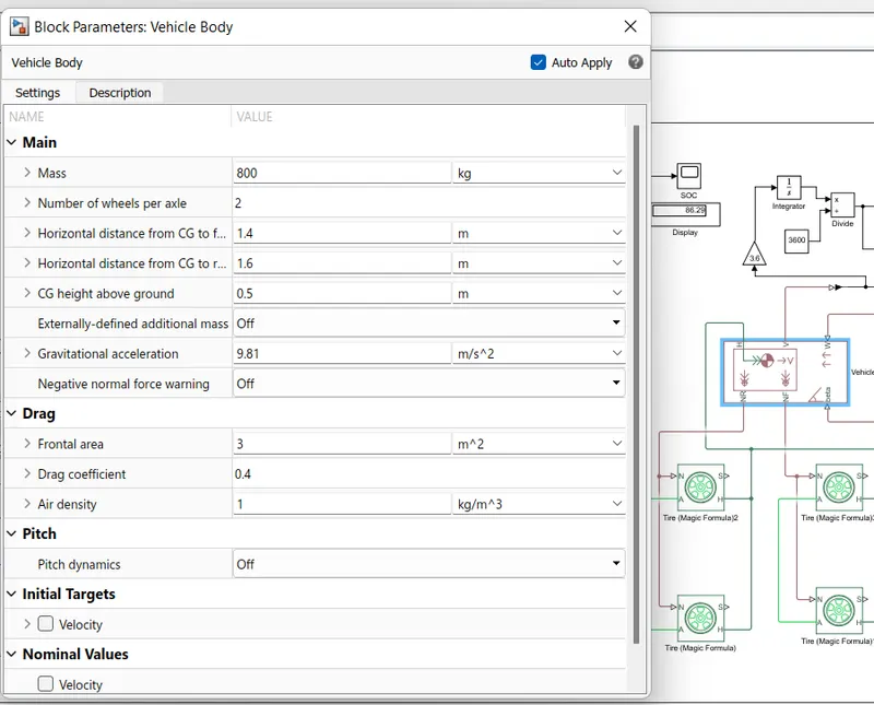
we considered following parameters-
frontal area= 3 m^2
drag coefficient=0.4
air density= 1 kg/m^3.
mass= 800 kg
9) battery model=
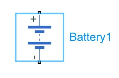
- the battery is connected as the source to the model so that the power could be generated and the same power is transmitted accordingly to all the operating sources and load demand of driver.the terminal connection are
+ = the positive terminal of the operating sources
- = the negative terminal of the operating sources
- the battery block implements a generic dynamic model that represents most popular types of rechargeable batteries like lithium ion type battery.
- the complete battery soc block is-
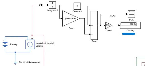
-it includes the controlled current sources to draw controlled current from battery to load ,the electrical reference , PS-simulink converters,the scope and SOC estimate.
- SOC estimation:
-for this we use a simple method called coulomb counting.
- coulomb counting is a technique used to track the state of charge of a battery pack.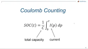
- it works by integrating the active current flowing in ampere over time to derive the total sum of energy entering or leaving the battery pack.this produces a capacity that is measured in amp-hours.
-the SOC estimate block is connected with battery through controlled current source block from which integrator block counts all time period +,- values of current.the gain considered at (1/100*3600) Ah capacity of battery,then the sum block substract the SOC from initial set constant block.this gives us the battery SOC estimate.
-the parameters of battery block are-
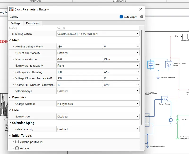
we consider the following parameter values for this battery
- nominal voltage=350 V
- rated capacity=100 A*hr
- initial state of charge= 100 %
10) controlled voltage source
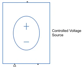
it is located in the simulink library at electrical sources.
it is used to control the voltage which is connected to the positive reference of the controlled PWM voltage in the form of a signal by the longitudinal driver model acceleration command and another controlled voltage source 2 is used to connect to the H-bridge BRK terminal. the negative sides of both the sources are connected to the electrical reference as shown above.
11) controlled current source=
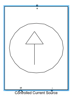
it is located in simulink library at simscape /electrical /specialized power systems / fundamental blocks / electrical sources .
this block converts the simulink input signal into an equivalent current source.the generated current is driven by the input signal of the block which is shown as symbol of 's'.the arrow in block shows positive current direction.this current source may be used for the both AC and DC current controls.without giving any signal or values to the control as input it will not work.here the controlled current source +Ve and -ve terminals are connected to the battery +ve and -ve terminals respectively as shown in model.the input signal 's' is connected to the power control unit current sensor signal I which is the physical signal.
12) multiport switch=
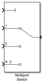
this block determines the which inputs to the block passes to the output and this is depends on the value of first input.
the first input is the control input and others are data inputs.the value of the control input determines which data input passes to the output.
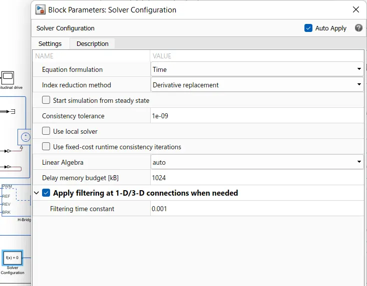
13) solver configuration
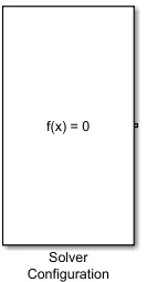
it is placed in the power control unit for the mathematical values in the model solver settings at the simulation time.
14) current sensor
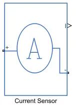
it is located in the simulink library at electrical sensors.
this is used to measure the current flowing through the H-bridge.the positive and negative terminals of the current sensor are connected to the DC motor and H-bridge block respectively and the signal is connected to the controlled current source in the battery as a physical input signal from the H-bridge circuit.
15) electrical reference
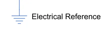
it is located in the simulink library at electrical elements.
it is used to connect all the terminal of the negative signals and the reference values as the ground.
16) mechanical rotational reference
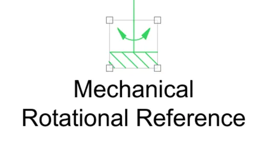
it is representing as a mechanical ground reference point that is as a frame part which is used to connect rotational parts to the ground.
17) inertia

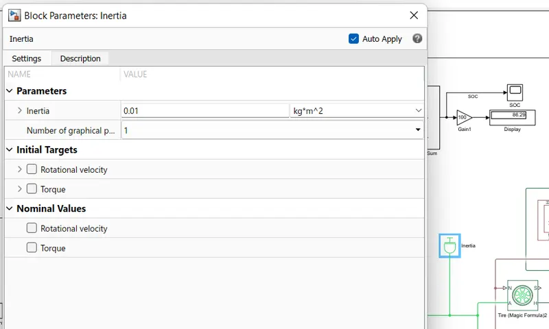
it is used to represent the ideal mechanical rotational inertia which is the reference port to give the positive inertia torque with the terminal used to connect to the reference one.
18)display

it is located in the library simulink at simulink / sinks.
it is used to display the value that connected to this block in the form of physical form.
19) scope=
it is also located at different places as,
simulink/commonly used blocks
simulink/ sinks
HDL coder / commonly used blocks
HDL coder / sink
it is used to display the signals generated during simulation.
20) powergui
it is present at simscape / electrical / specialized power systems / fundamental blocks.
it is used with simulation of power systems and power electronics.
it is used for the analysis and measurement of parameters like voltage ,current , active power, reactive power.it gives the steady state values of the system.
21) PS-simulink converter:
it is located in the simulink library at utilities.
it is used to connect the line from physical signal to simulink which act as an converter.
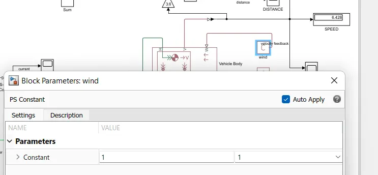
22) PS constant=
this block generates a physical signal of a constant value.it has only one output port which is a physical signal

we specified the value and unit of the signal as the constant parameter.in our model we are using 2 PS constant blocks which are connected accross the W and beta ports of the vehicle.
results=
To get the results of this model we have to keep the stop time to 2474 sec or above because of the given drive cycle source with FTP (2474 seconds).
so ,now i am running the model by selecting the stop time as 2474 second by clicking the run button at the top of the window.
so.we can see the following observation which is shown in the figure.
vehicle speed scope=
this plot can be observed from the scope which is connected across the drive cycle source and feedback velocity which is coming from the transmission subsystem and the longitudinal driver block.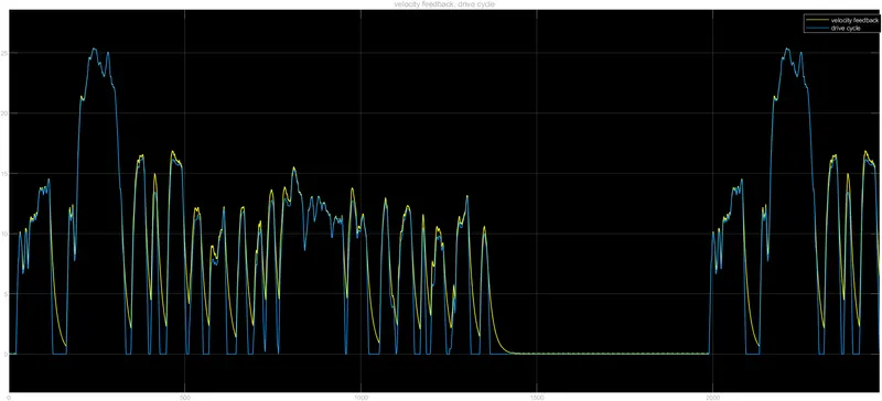
- from this response we can see ,there are two signals.the blue signals shown is the drive cycle data and the yellow signal represents the vehicle body speed.
-the longitudinal driver successfully maintains the drive cycle data,processes it and controls the vehicle speed according to the reference speed.
-if we observe them,we can say that they are looking similar but not exactly.because when we driving the car there will be speed variation according to the time,sudden stops and some other factors also affect such as type of road and rolling resistance etc.
-so there will be same movements like high speed ,low speed but due to the factor effected in the real time there will be a variation from the original drive cycle.
SOC SCOPE=
the below graph has been observed form the scope block which is connected to the battery.
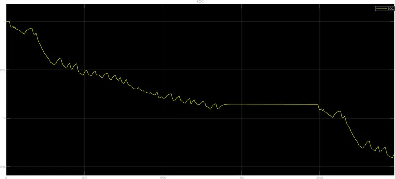
-the SOC graph shows the state of battery varies over the drive cycle time.
-initially the battery SOC is 100 %
- as the the simulation starts then there will be a fall of SOC.
- the charge of the battery gets decreased from 100 % to 86.29 %
- the spikes in battery SOC graph shows regeneration during the deceleration of the vehicle as battery starts recharging and motor acts as generator.
-again if we observe from that graph that in between 1400-2000 sec it is almost constant to zero speed which means that either the car is in neutral gear or it is in downhill road,so in that period the battery gets charged.
distance covered=
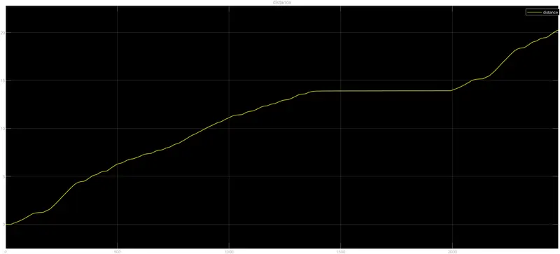
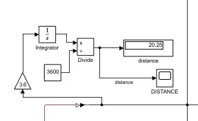
-vehicle speed obtained in m/s so we can convert this to km/hr by using gain block 3.6.
-we convert velocity speed to distance that is km/hr to only km by using integrator block, constant block of 3600,divide block.
- from this graph and display block ,we have seen that the total distance covered during the period of 2474 seconds is 20.25 km.
current scope=
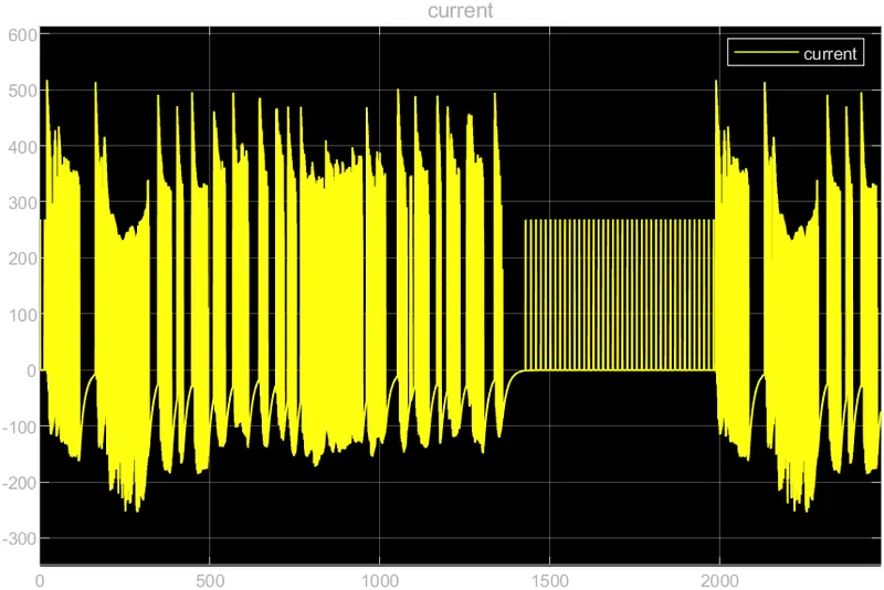
- the above graph shows the current variations of the motor according to drive cycle.
- the current sensor is connected between the H-bridge and DC motor senses the current changes and they are ploted through the scope block,so this current variation are observed from the changes in DC motor conditions.
- we can see that current increases according to acceleration and decreases according to the deceleration.
-when the vehicle is maintaining a constant acceleration or deceleration then the current is also maintaining its range according to it.
-at peak value the maximum current is approximately 510 A ,at neutral condition that is at 0 velocity the current value is also settled at nearby zero value and during deceleration of the car the current value is also going to decrease in negative values.
the link for this project is=
https://drive.google.com/file/d/1PtPm729UfdO1EJoCQxfm0-pOqSVdci-3/view?usp=sharing
CONCLUSION=
- the above electric vehicle/car model has been created by using the DC motor and battery with all the necessary components by using simulink and the model is simulated with all the proper procedure.
- the simulation can be carried out by deciding the overall specification that the vehicle should achieve,in this manner all components can be choosen and then the actual model could be manufactured.
- this simulation gives the vehicle speed output ,current flowing throught the battery and the state of charge as well as the distance travelled within the simulation running time.
- the total distance covered during the period of 2474 seconds is 20.25 km.
- the SOC of the battery is discharged efficiently up to 86.29 % from full charge.
- this model has been attached above as a slx file.