Final Project: Design of an Electric Vehicle
Electric vehicles are expected to become the next disruptive force in technology and transportation. They have the power to completely alter the ways in which energy is produced, used, and directed. The negative environmental effects of conventional cars can be mitigated in part by using electric vehicles. However, they have been shown to have a great deal more positive effects on society. Improvements in overall energy generation and consumption are required with the introduction of electric vehicles. They have demonstrated how crucial it is to discover alternative fuel sources and how they can have a good impact on the environment and society at large.
The following is a block diagram for a simulation of an electric vehicle:
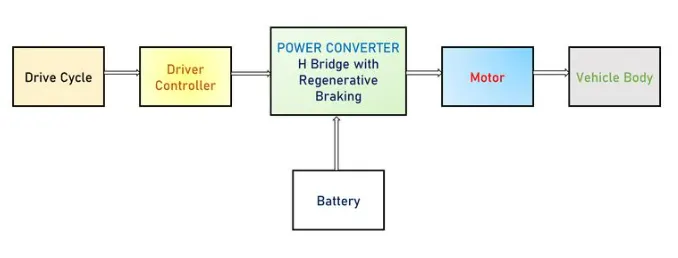
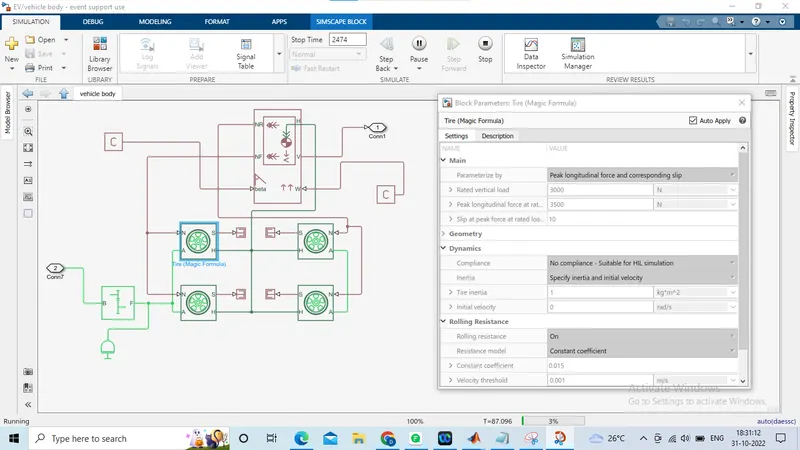
Vehicle Body: The vehicle frame, which includes its axles, transmission system, wheels, and chassis, is known as the "vehicle body." Simulink offers an easy-to-use "Vehicle body" block in the simscape library where the input parameters like the vehicle's mass, drag, pitch, etc. Wheels are also part of the vehicle's physical body are represented by "Tires (Magic Formula)" in the Simscape library. To imitate the transmission system in addition to these elements, a straightforward gear block is added.
Motor:
An electric vehicle motor is the device that transforms electrical energy from the battery into mechanical energy so that the wheels can be moved. The actual electric vehicles use a variety of motors, including induction motors, BLDC motors, internal permanent magnet synchronous reactance motors, and others. In this simulation, DC motor is used.
Power Converter:
The processing core of an electric vehicle can be viewed as the power converter. Power electronics are the main components that makes it possible to control an electric car. Since the battery voltage is a constant DC, the motor always operate at a constant speed, making it impossible to regulate its speed. The power converter, which is made up of inverter or chopper topologies depending on the type of motor solves this issue by controlling the motor's speed.
Driver Controller and drive cycle:
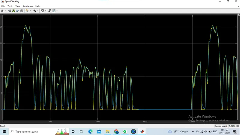
These blocks are unique for simulation purposes since they serve as the model's simulation's reference. The drive cycle is only a velocity vs. time plot that is sent to a driver controller, which compares the input speed with the current output speed to determine the error. This fault is then fixed by accelerating or braking to complete the reference drive cycle.
Battery:
The battery serves as the electric car's fuel supply. A battery pack for an electric vehicle is made up of numerous individual cells with lesser voltages that are connected in series to create a battery pack with a higher net voltage. Lithium Ion batteries are used in the vehicles of many EV manufacturers, including Tesla, Nissan, Audi, and others. This battery connects to a motor controller and provides a steady DC voltage.
simulink model:
The simulink model of the electric car used for simulation is shown below:
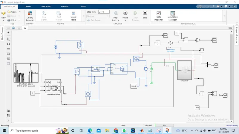
The various sub-systems of the model includes:
Vehicle body sub-system:
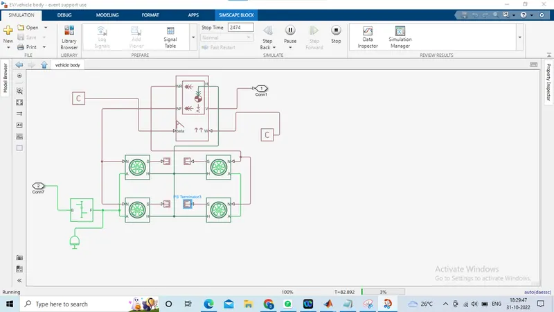
The vehicle body sub-system consists of blocksets like tire,simple gear and vehicle body.
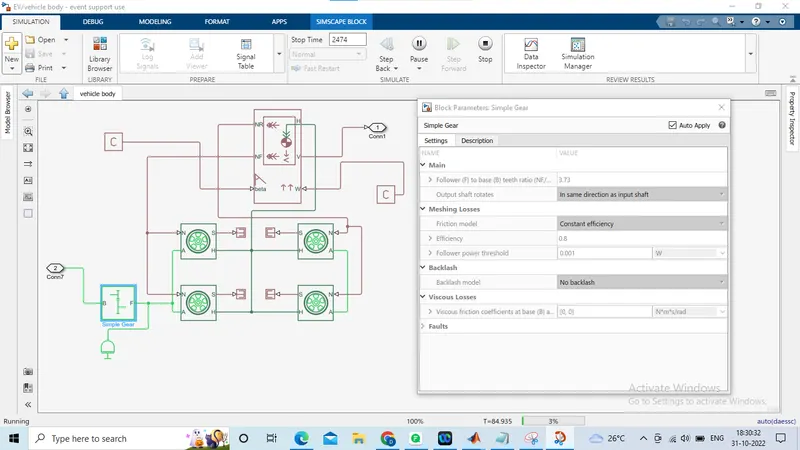
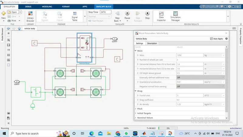
DC Motor:
Simulink offers an integrated model block for DC motors, that transforms electrical input into mechanical rotating output.
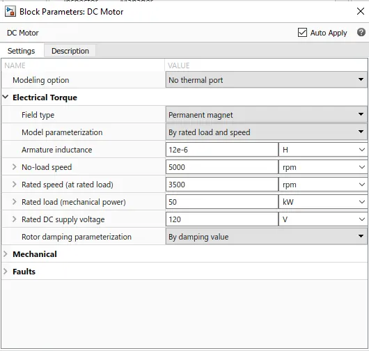
The DC motor model used for simulation and its parameters settings are presented below
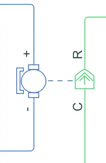
The blue colour in this illustration represents the motor's electrical side and the green colour represents its mechanical side. The model parameterization is done by rated load and speed and the motor field type is maintained as permanent magnet.
Motor controller
The Motor controller includes H-bridge and controlled PWM voltage.
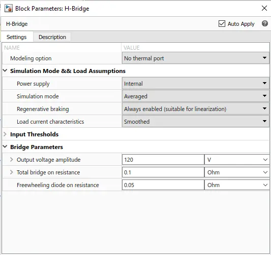
The DC motor is controlled through H-bridge. The H-bridge motor drive block is used in the simulink model, which can be driven in PWM or Averaged mode by the Controlled PWM Voltage block.
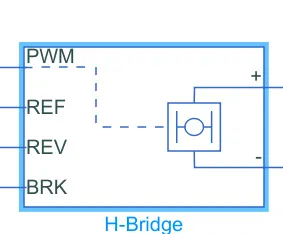
When in PWM mode, the motor is powered if the PWM port voltage is greater than the enabled threshold voltage. In Averaged mode, the PWM port voltage divided by the PWM signal amplitude parameter yields the ratio of the on-time to the PWM period.
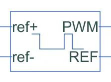
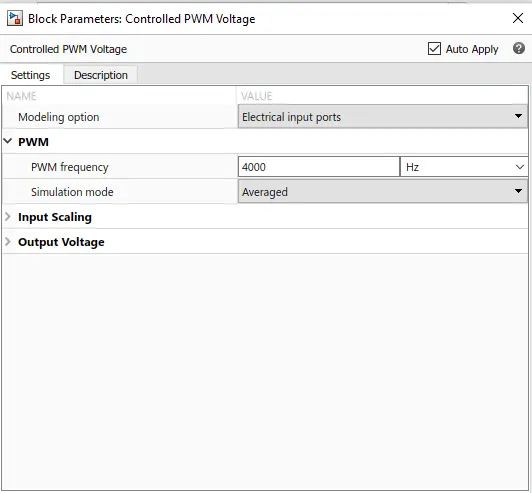
Controlled PWM Voltage is a built-in block available in Simulink. This block is utilised to supply the H-Brdige circuit with the right pulse inputs.
The PWM frequency in this case is 4000 Hz. Additionally, the simulation mode mimics the H-Bridge circuit's averaged mode.
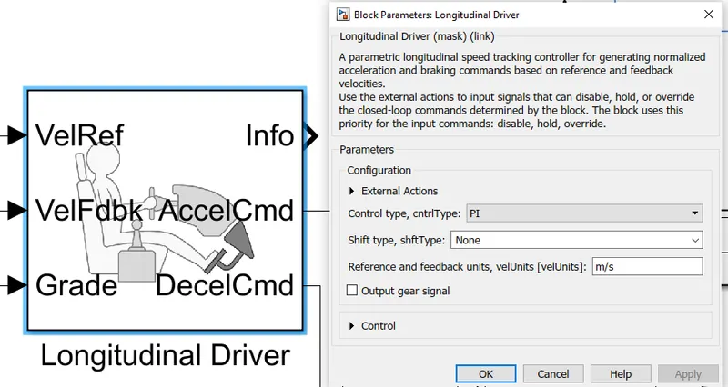
Longitudinal Driver:
it is a parametric longitudinal speed tracking controller. The powertrain blockset includes an internal block called Longitudinal Driver. For the purpose of producing normalised Acceleration and Braking instructions based on reference and feedback velocities.
The input drive cycle data is transmitted into the VelRef port, which is the reference velocity port. The feedback velocity is represented by the VelFdbk port. The driver block creates accelerating and braking signals to reduce the error between the two concerned velocities by comparing the feedback velocity with the reference velocity.
Since no inclination is taken into account in this simulation, a constant block with the value 0 is considered as grade.
Battery Pack:
A simple battery block is used to model the battery pack.
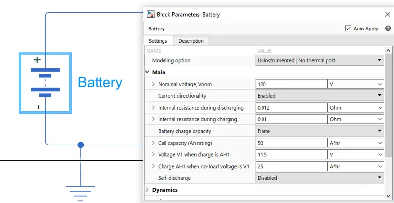
A Current Sensor & Controlled Current Source pair is linked to the battery to guarantee that it delivers current in accordance with the needs of the motor controller rather than the rated current.
Drive cycle source:
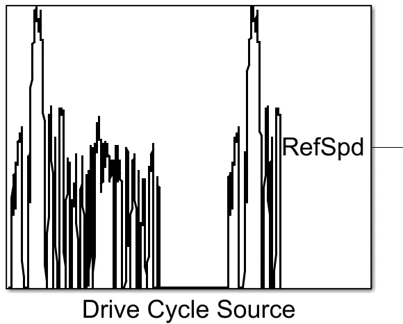
The simulation reference speed is provided via the Drive Cycle Source block. It creates a longitudinal drive cycle that is either predefined or user-specified. The standard FTP75 drive cycle was chosen.
Results:
Vehicle speed Tracking:
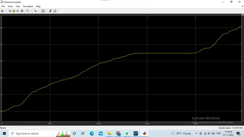
Distance travelled:
The distance travelled by the vehicle is more than 5km for the simulation time period of 2474 secs.
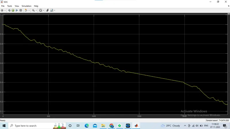
SOC of battery:
The SOC of the battery has been reduced to 20%.
Conclusion:
This project helps to understand the role of different systems in designing an electric vehicle. The simulink model is constructed using various power train blockset from simulink library. Simulation of the model was accomplished using the typical FTP75 drive cycle and the results are verified. The creation of a MATLAB model of electric car helps to perform a real-time simulation of an EV, which includes the operation of a motor controller and the part it plays in the regulation of the electric motor.