Final Project: Design of an Electric Vehicle
AIM
To create a MATLAB model of an electric car which uses a battery and a DC motor, by choosing suitable blocks from Powertrain block set.
THEORY
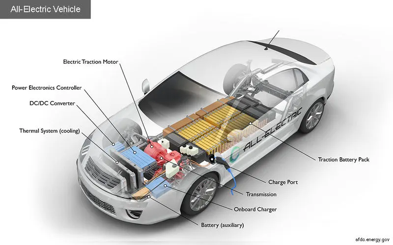
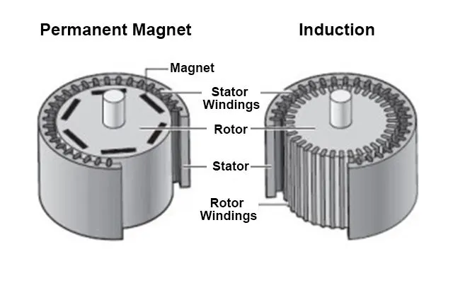
An electric car is a vehicle that is propelled by one or more electric motors, using energy stored in rechargeable battery packs. These are eco-friendly and has higher efficiency compared to ICE cars. An electric vehicle is 69-72% efficient when counted against stored chemical energy and around 59-62% efficient when counted against required energy to recharge. They use electric motors for propulsion. The most common types of motors used are Permanent Magnet Synchronous Motor (PMSM) and three phase induction motor.
Motor comparison,
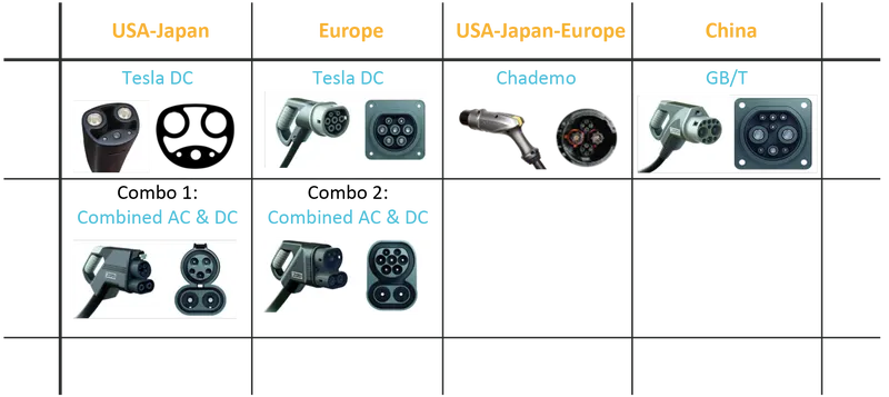
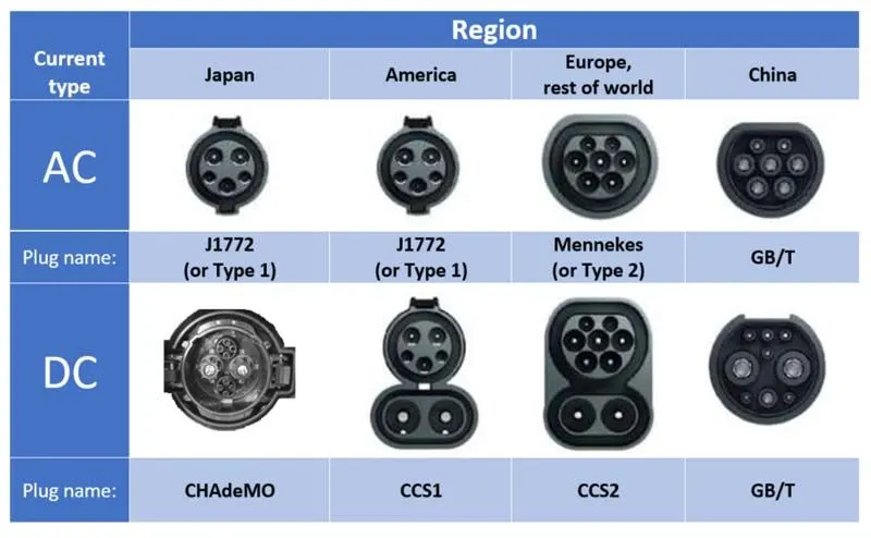
The battery packs are recharged using AC/DC charging technologies. AC charging is slow as it has to be converted to DC. Hence for fast charging DC chargers are used. The charging sockets has different standards as shown below,
BLOCK DIAGRAM
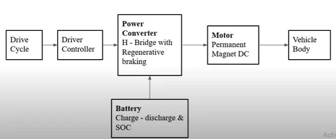
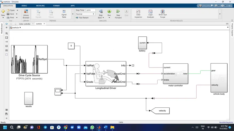
The block diagram for an Electric vehicle which uses a battery and a DC motor is shown below,
Create model
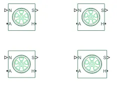
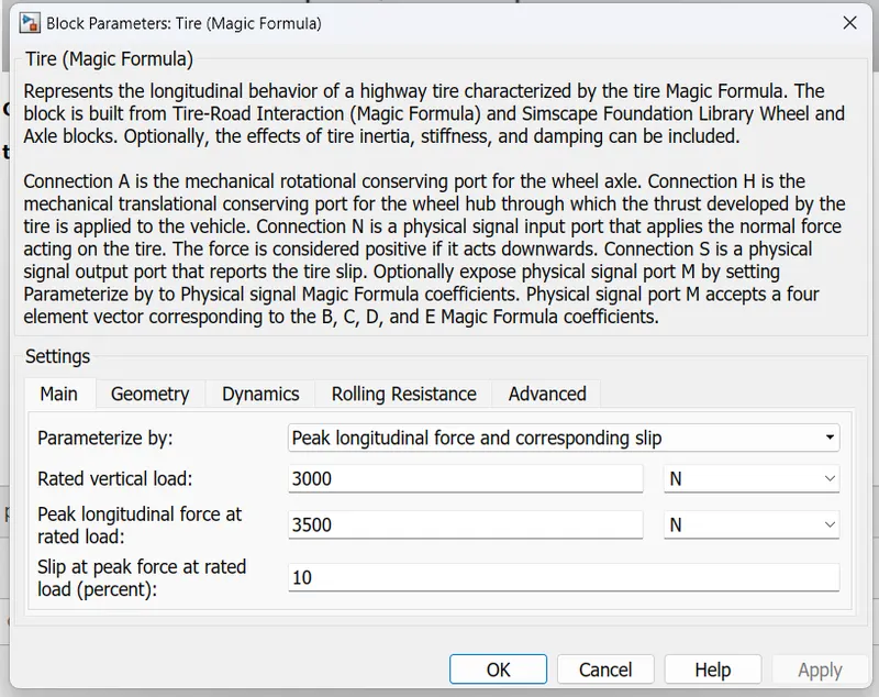
tires
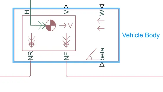
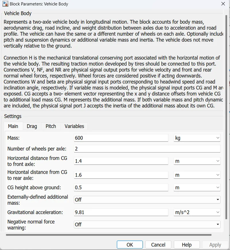
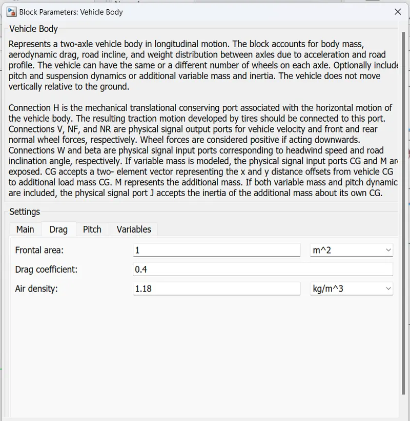
VEHICLE BODY:
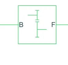
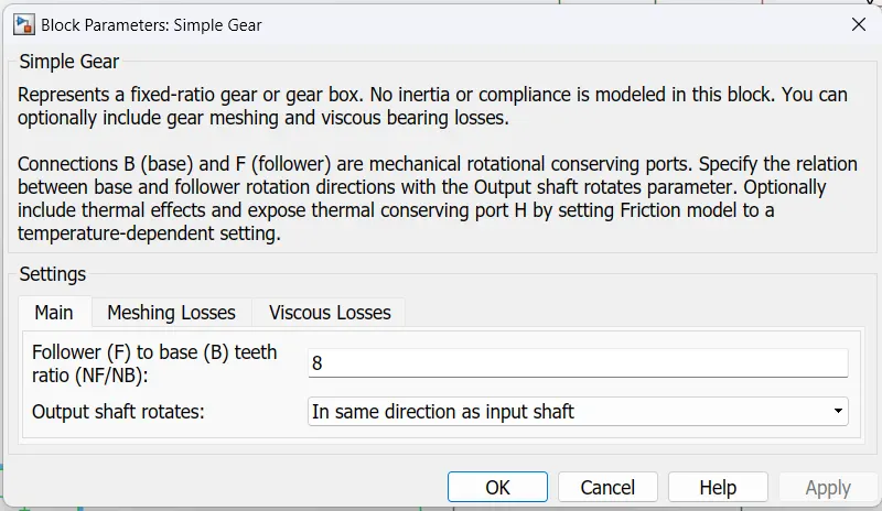
SIMPLE GEAR:
POWER BLOCKS:
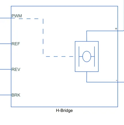
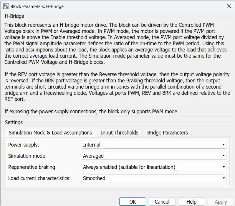
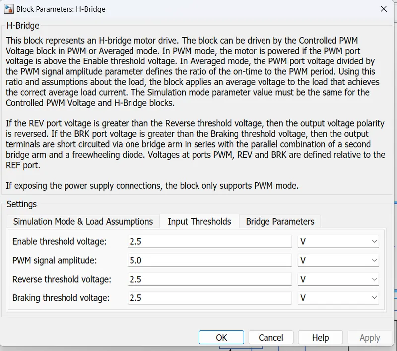
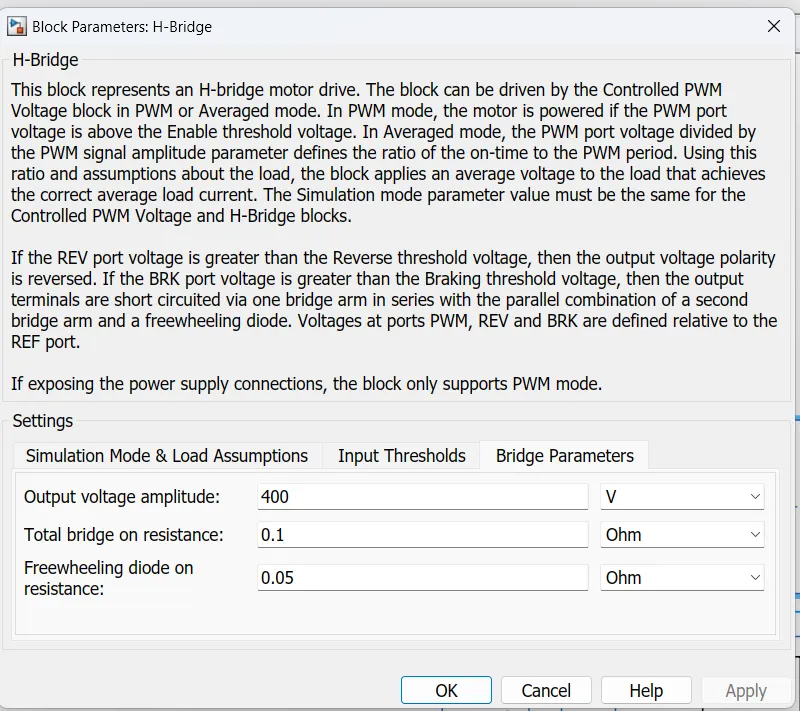
H-BRIDGE :
CONTROLLED PMW VOLTAGE:
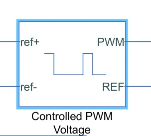
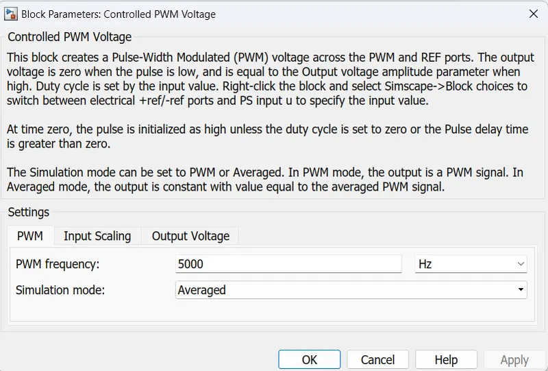
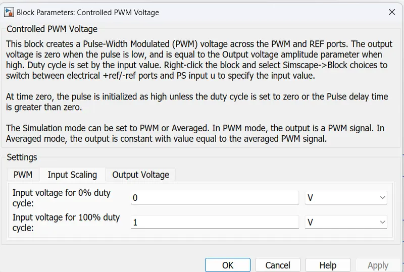
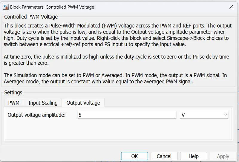
The H-Bridge block output is a controlled voltage that depends on the input signal at the PWM port. If the input signal has a value greater than the Enable threshold voltage parameter value, the H-Bridge block output is on and has a value equal to the value of the Output voltage amplitude parameter.
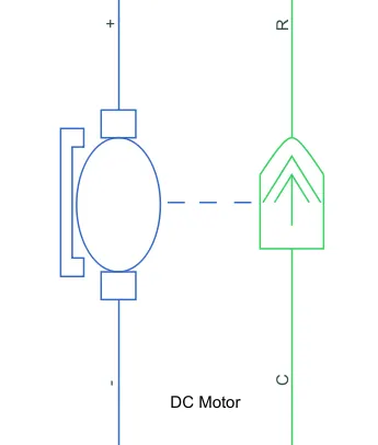
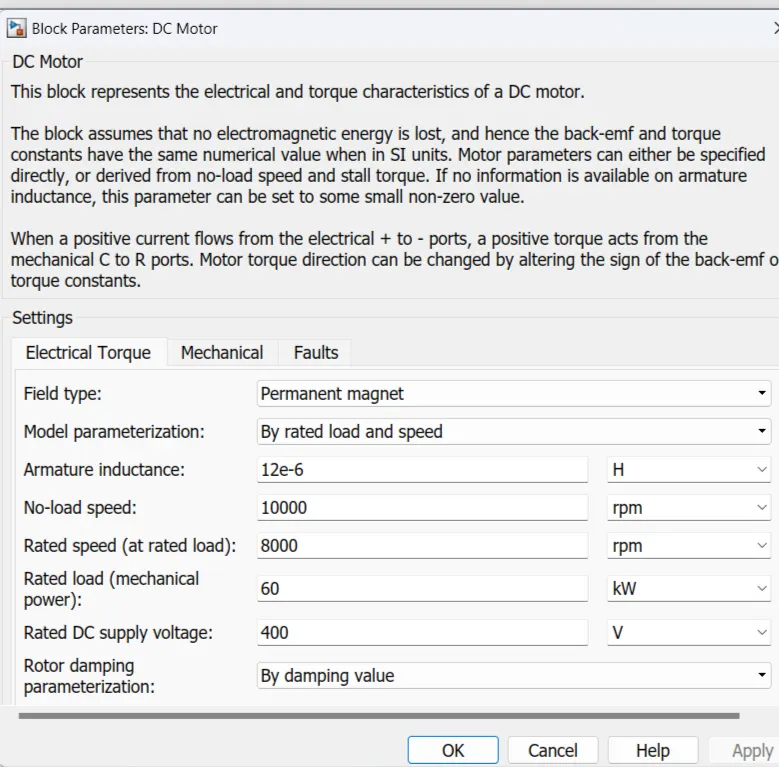
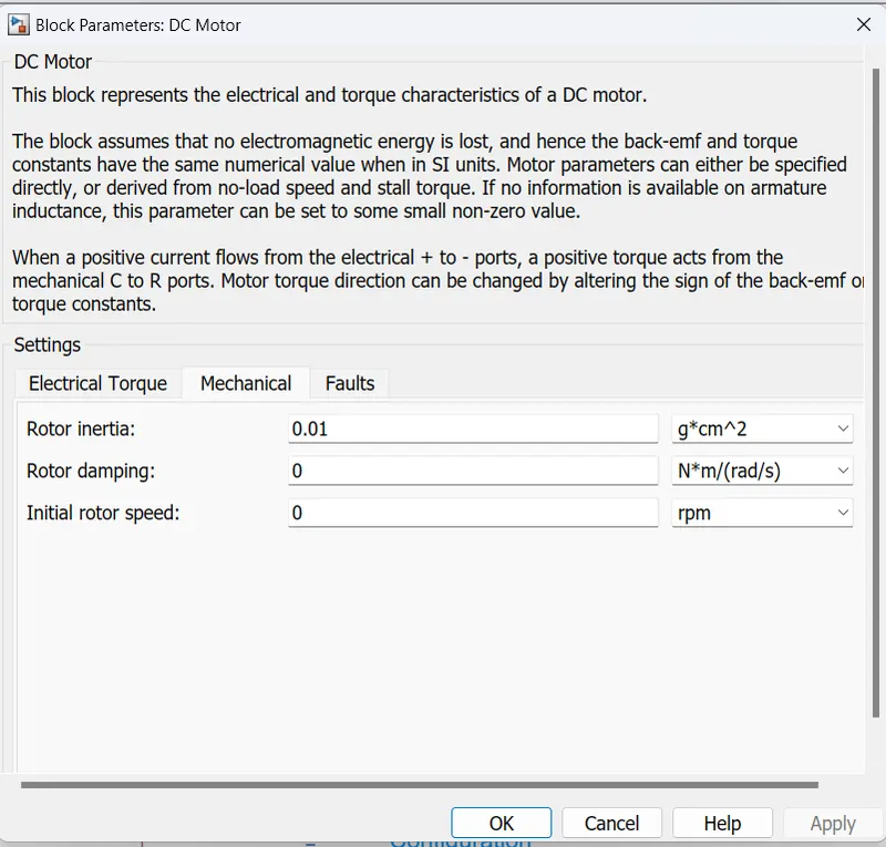
DC MOTOR:
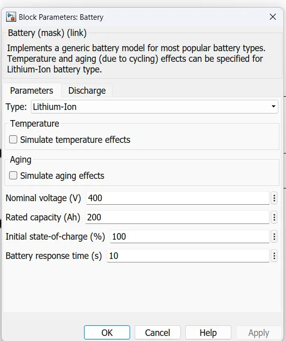
BATTERY:
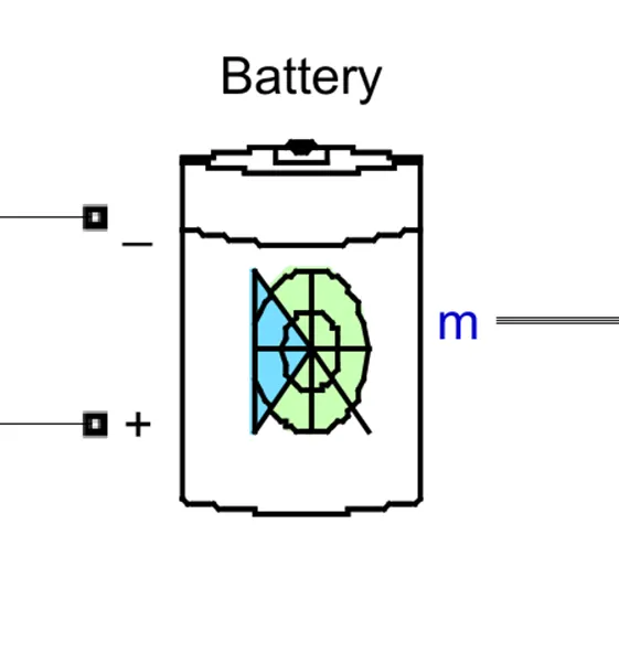
TOOLS:
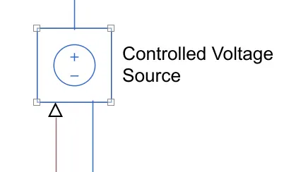
CONTROLLED VOLTAGE SOURCE:
CONTROLLED CURRENT SOURCE:
The Controlled Current Source block provides a current source controlled by a Simulink signal. The positive current direction is as shown by the arrow in the block icon.
CURRENT SENSOR:
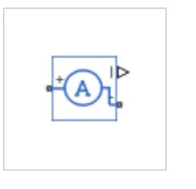
The Current Sensor block represents an ideal current sensor, that is, a device that converts current measured in any electrical branch into a physical signal proportional to the current.
VOLTAGE SENSOR:
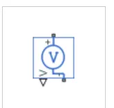
The Voltage Sensor block represents an ideal voltage sensor, that is, a device that converts voltage measured between two points of an electrical circuit into a physical signal proportional to the voltage.
INTEGRATOR:
The Integrator block outputs the value of the integral of its input signal with respect to time.
GIVING THE DRIVE CYCLE:
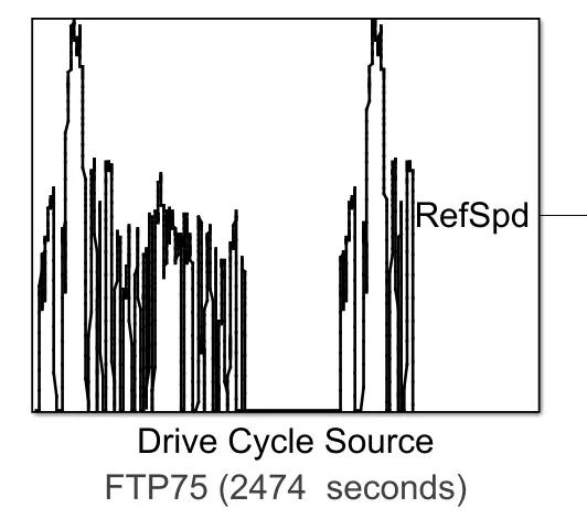
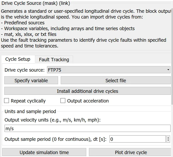
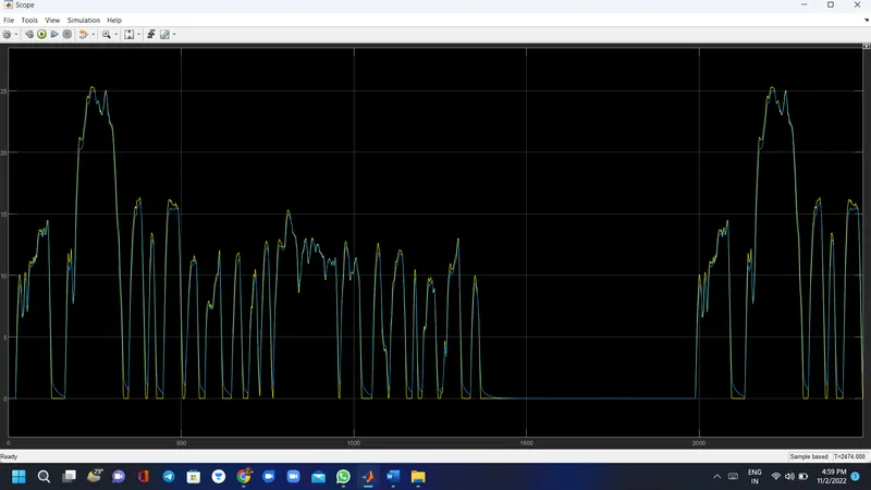
It generates a standard or user-specified longitudinal drive cycle. the block output is the vehicle's longitudinal speed. use the fault tracking parameters to identify drive cycle faults within the specified speed and time tolerances.
model
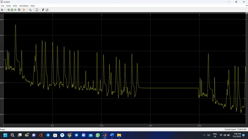
output of drive cycle
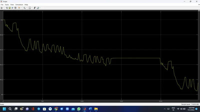
soc of battery
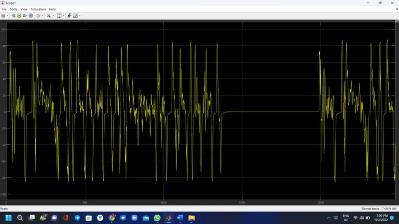
battery current
battery voltage
CONCLUSION:
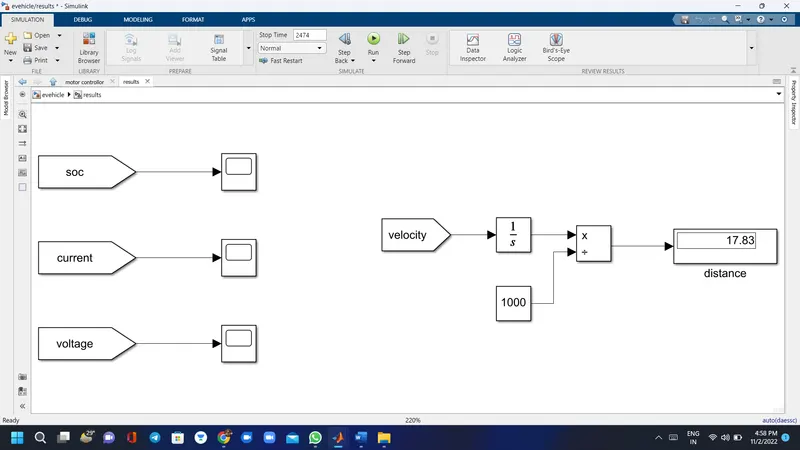
The Ev model has been created with Simulink. and the model simulated with Drive cycle source (FTP575(2474sec)) the simulation has produced the results of vehicle velocity with respect to acceleration and the current flowing state of charge as well as the distance traveled in simulation time The vehicle traveled 17.83 kmph in 2474 sec.