Final Project: Design of an Electric Vehicle
MATLAB model of electric car which uses a battery and a DC motor
Electrical Vehicle:
The vehicle which uses the Electrical motor as Engine and Electrical power as fuel source is known as Electrical Vehicle.The electrical motor are of diffent types according to their advantanges their are chosen.The fule source is battery which is a DC supply. There are two types of power supplies they are AC and DC. According to the type of motor we are choosing the supply must be given to it. If we us AC motor as a engine we need a converter because the power source is of DC type,the converter converts the DC to AC. If we are using DC motor there is no need of any conversion .
The electrical vehicles are clsified in to different type
Battery Electrical Vehicle(BEV): Battery Electric Vehicles, also called BEVs and more frequently called EVs, are fully electric vehicles with rechargeable batteries and no gasoline engine. All energy to run the vehicle comes from the battery pack which is recharged from the grid. BEVs are zero emissions vehicles, as they do not generate any harmful tailpipe emissions or air pollution hazards caused by traditional gasoline-powered vehicles.
Plug-in Hybrid Electrical Vehicle (PHEV): Plug-in Hybrid Electric Vehicles, or PHEVs, have both an engine and electric motor to drive the car. Like regular hybrids, they can recharge their battery through regenerative braking. They differ from regular hybrids by having a much larger battery, and being able to plug into the grid to recharge. While regular hybrids can (at low speed) travel 1-2 miles before the gasoline engine turns on, PHEVs can go anywhere from 10-40 miles before their gas engines provide assistance. Once the all-electric range is depleted, PHEVs act as regular hybrids, and can travel several hundred miles on a tank of gasoline. All PHEVs can charge with charger, but most PHEVs are not capable of supporting fast charging.
Hybrid Electrical Vehicle(HEV): Hybrid Electric Vehicles, or HEVs, have both a gas-powered engine and an electric motor to drive the car. All energy for the battery is gained through regenerative braking, which recoups otherwise lost energy in braking to assist the gasoline engine during acceleration. In a traditional internal combustion engine vehicle, this braking energy is normally lost as heat in the brake pads and rotors. Regular hybrids cannot plug into the grid to recharge.
Here we are intrested in designing the Electrical Vehicle. Below blow diagram will show the power flow and how thay the working and communicating.
Block Diagram:
We need to understand the flow of power before designing the EV.
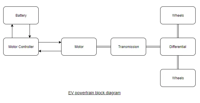
The main parts of the EV system are
- Battery
- Controller
- Motor
- Transmission
Battery: It is Power source to the vehicle. According to the requirment the battery back is designed i.e., the Energy and voltage requirment. The battery is charged using a charger, it may be on bord charge or off bord charge. Most the vehicles have on bord charge system. The battery has a controller which takes care of the charging, discharging, temperature control ect.,
Controller: The controller will control the motor according the driver requrment. It helps in controlling the speed torque and runs the motor in a smooth way.
Motor: The motor is the Engine for the vehicle. The motor are clasified in to two types they are
DC motor-
- Saparatly exicited DC motors
- DC Series motors
- DC shunt motor
- DC compound Motors
AC motors-
- Induction Motor
- Synchoronous motor
- Permanent magnet Synchronous motor
- Switched Reluctance Motor
- BLDC motors
According to their charectaristics, advantages and controlling the motors are choosen accordingly. Most commly used motors are Permanent magnet Synchronous motor,Induction motor, BLDC and DC motors
Transmission: The motor power is now transmited to the wheels through a transmiter and the differential to wheels.
For high efficiency the vehicle can be provided with Regenerative braking. Which will give supply back to battery during braking action.The motor made to work in both motoring and genereating modes.
During motoring mode the power is flows feom battery to wheels from controller to motor to transmission.
During Generating or Braking mode the power is flowing from wheels to battery throgh transmission to motor to controller.the flow is opposite to motoring mode. At this mode the motor is made to work as generator and energy is stored in the battery.
For designing the EV we need to calculate the how much transmission force is requied,motor power, speed of the vehicle, weight of the vehicle ect., are the main parameters need to known.
In this model the parametes are assumed as
Motor:
Type of motor = Parmanet magnet synchronous motor
Power = 60Kw
Voltage = 300v
No load speed = 1500 RPM
Battery:
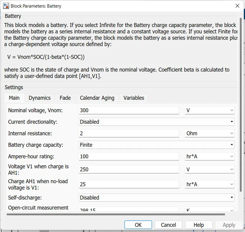
Battery capacity = 100Ah
Voltage = 300v
Other paramers:
Weight = 1400kg
Wind velocity = 0
Gradient = 0
Rolling resistance as negligable
Matlab Model:
1. Vehicle Body:
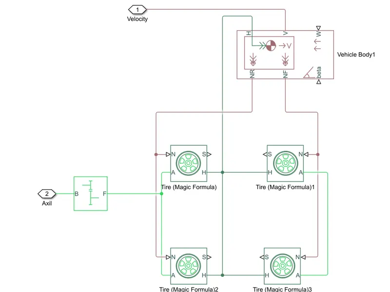
Blocks:
Tire: The 4 tire blockes are taken for the vehicle. The parameters are kept default values only. The connections are made as per shown above. The 4 wheels are made as 2 pairs one pair for Front and another for Rare side of the vehicle.
For more infromation refere to the link below
Tire information and configuration
Vehicle Body:
It is the simpies form of the vehicle body where the dimentions,weight,gradient and wind velocity can be applied.They are connected to the Front and Rare tires as shown. All the parameters kept default
For more information refere to the link below
Vehicle Body configuration and working
Simple Gare:
The Simple gare is conected to the axil of the tires. The gair ratio is taken as 2, which the speed is doubled. The in put is connected to motor rotor and output is connected to Axil.
For more information refere to the link below
These blockes to gether formed as subsystem .
Electrical Vehicle Model:
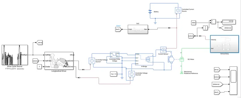
2. Motor and Controller:
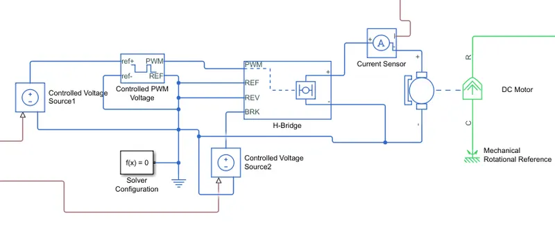
Motor:
The motor is taken as DC motor. The parameters are shown below and all other parameters are taken as default
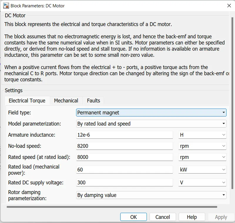
The R is rotating part of the motor which is connected to the axil of the vehicle. C is the casing part of the motor which is connected to mechanical referance to make it steady. The supply is connected to the H-Bridge controller.
For more Information refere to the link below
H-Bridge Controller:
The H-Bridge controller will controll the motor according to the driver requirment.The block parametrs are taken as dhown below. The PWM is connected to the Controlled PWM Voltage output. Brake is connected to Controlled voltage source which is connected to the decelaration of the Longitudenal Driver. All other are connected to Electrical referance as shown above.
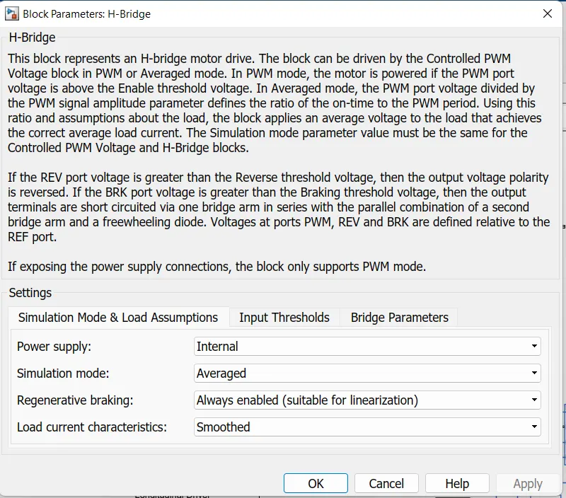
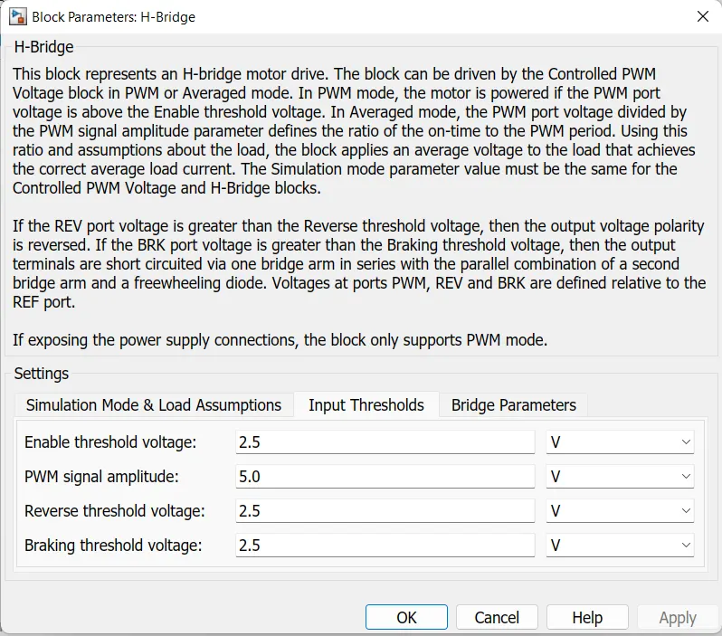
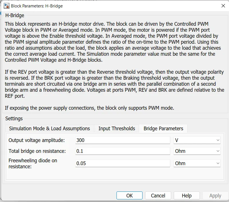
For more Information refere to the link below
Controlled PWM voltge:
It will generate the PWM pulses for the Hbridge according to the driver requriment. The referance is connected to the Controlled voltage source whicjh generate the voltage by taking the refeance from driver requirment. The Referance voltge vill generate the pulses accordingly Which is given to the H Bridge so that the motor is controlled accornd to the driver requirment.
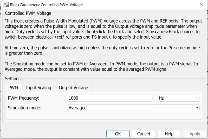
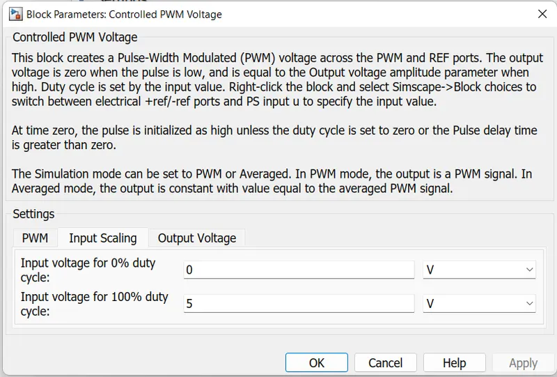
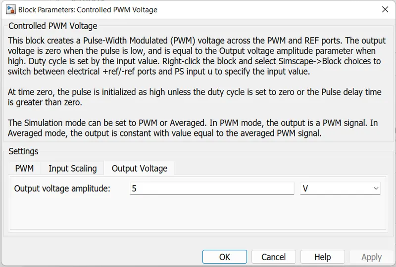
For more Information refere to the link below
Current sensor :
It is used to measure the current.
Controlled Voltage Source:
Generate the constant voltage acoording to the referance signal.
Solver Configer:
It is used to run the Simscape model.
Electrical referance:
It is the common ground for all electrical components.
3. Drive cycle and Longitudinal Driver:
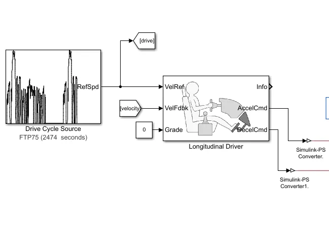
Longitudinal Driver :
The block take the drive cycle as referance and speed from the vehical body as feedback signal and generate the acceleration and deceleration command according to the drive cycle. Acceleration command is given to the PWM through the Controlled voltage source and deceleration command is given to the braking in PWM through cotrolled voltage source.
for more infomation refere to the link below
Longitudinal driver information
Converters:
In this model there are simscape blocks and normal blocks. The normal blocks will generate the physiscal signals and simscape block will generate the electrical signal. so to connect these two signals a ps-simulink and simulink-ps converter is needed.
for more infomation refere to the link below
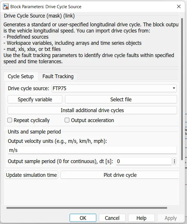
Drive Cycle:
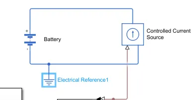
Battery:
Battery parameters
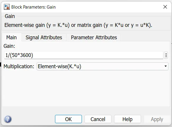
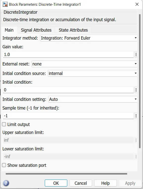
SoC calculation
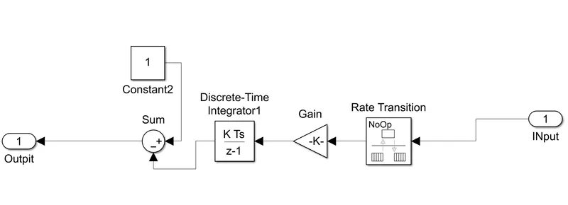
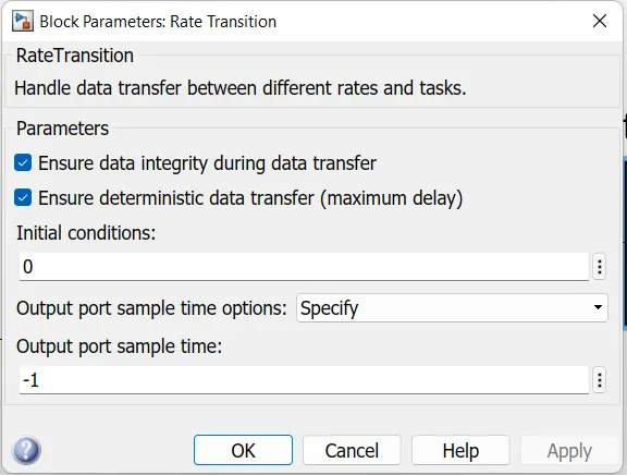
Rate Transition parameters
Gain parameters:
Discreat Time Intigrator parameters:
Distance Calculation:
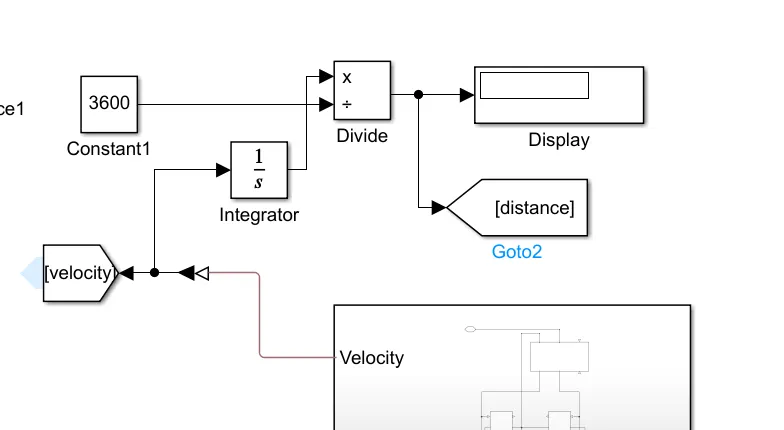
It is calculated from the vehicle velocity. Intigrating the velocity and dividing it with 3600 will give the distance in KM as outpunt we can obser ve in display.
OUTPUTS:
The outputs are taken as
Input drive cycle
Output vehicle speed
Distance covered
SOC of the battery
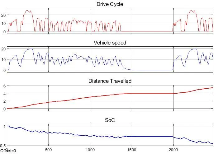
1st Graph indicates the drive cycle for the model. It is an example of FTP drive cycle.The max speed is up to 25 kmph
2nd graph indicates the Vehicle speed. The vehicle speed is almost following the input drive cycle but not accuratly. This is because of controll method used to control the motor. The top speed reached by the vehicle is 20 kmph only. This is a draw back of this model.
3rd graph indicates the distance travelled by the vehicle. It is travelled the distance of 5.503 km
4th graph indicates the SoC of the batter i.e, state of charge. At the starting the battery capacity is 100% and at the end of the drive cycle i.e., travelled distance of 5.503km the Soc is 50%.
Conclusion:
This model is designed at a base level with minimal calculation. In paractical each and every parameters of each block will effect the vehicle performance. As the model is designed at minimal level the vehicle is not able to reach the top speed provided by the drive cycle. To solve issue we need design more efficient motor controller so that it can follow the drive cycle.