Final Project: Design of an Electric Vehicle
Create a MATLAB model of electric car which uses a battery and a DC motor. Choose suitable blocks from Powertrain block set. Prepare a report about your model including following:
Objectives:
1. System level configurations
2. Model parameters
3. Results
4. Conclusion
Soln :
Introduction:-
ELECTRIC VEHICLE:-
An electric vehicle (EV) is one that operates on an electric motor, instead of an internal-combustion engine that generates power by burning a mix of fuel and gases. Therefore, such as vehicle is seen as a possible replacement for current-generation automobile, in order to address the issue of rising pollution, global warming, depleting natural resources, etc. Though the concept of electric vehicles has been around for a long time, it has drawn a considerable amount of interest in the past decade amid a rising carbon footprint and other environmental impacts of fuel-based vehicles.
An electric vehicle (EV) is a vehicle that uses one or more electric motors or traction motors for propulsion. An electric vehicle may be powered through a collector system by electricity from off-vehicle sources, or may be self-contained with a battery, solar panels, fuel cells or an electric generator to convert fuel to electricity. EVs include, but are not limited to, road and rail vehicles, surface and underwater vessels, electric aircraft and electric spacecraft.
EVs first came into existence in the mid-19th century, when electricity was among the preferred methods for motor vehicle propulsion, providing a level of comfort and ease of operation that could not be achieved by the gasoline cars of the time. Modern internal combustion engines have been the dominant propulsion method for motor vehicles for almost 100 years, but electric power has remained commonplace in other vehicle types, such as trains and smaller vehicles of all types.
Commonly, the term EV is used to refer to an electric car. In the 21st century, EVs have seen a resurgence due to technological developments, and an increased focus on renewable energy and the potential reduction of transportation's impact on climate change and other environmental issues. Project Drawdown describes electric vehicles as one of the 100 best contemporary solutions for addressing climate change.
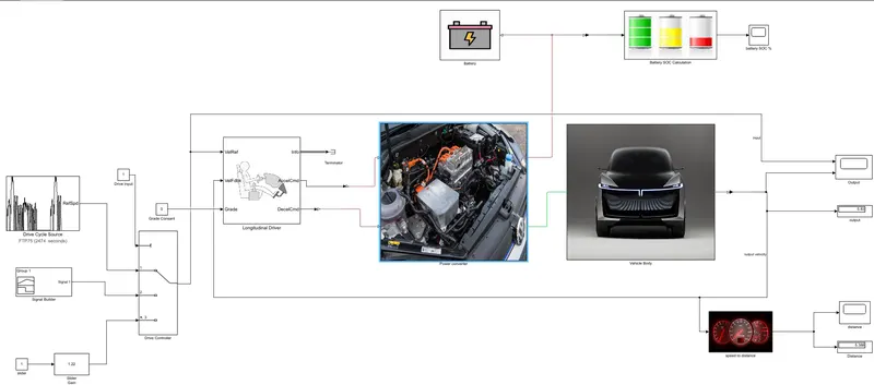
Block diagram :
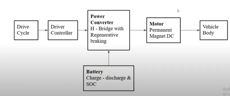
Designing an Electric Vehicle can be divided into sub blocks as shown above, Vehicle body block describes the physical components such as tire,vehicle body and gear. Motor block uses the physical blocks such as DC motor, IC motors etc. Power Converter blocks acts like heart of the vehicle all the components are inter connected to power converter block. Drive cycle and Drive Controller block acts like input to the vehicle.
Types of Electric Vehicles:-
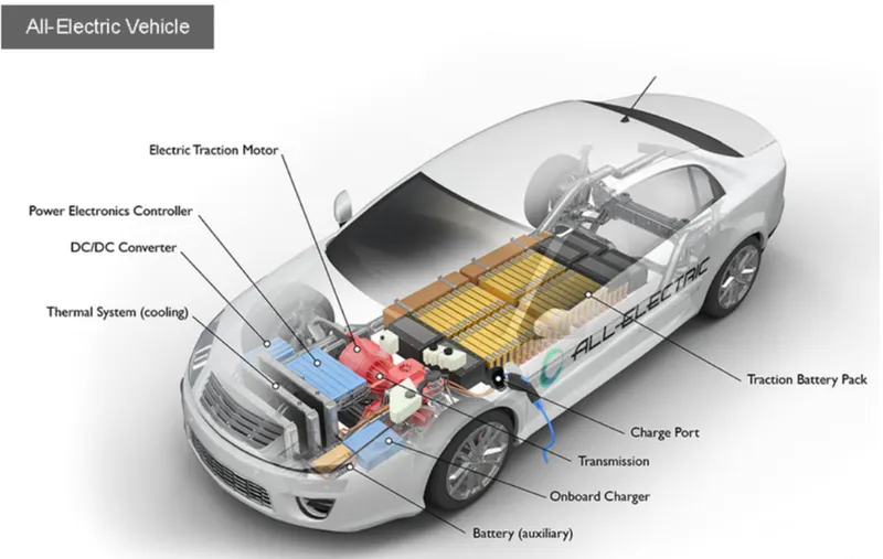
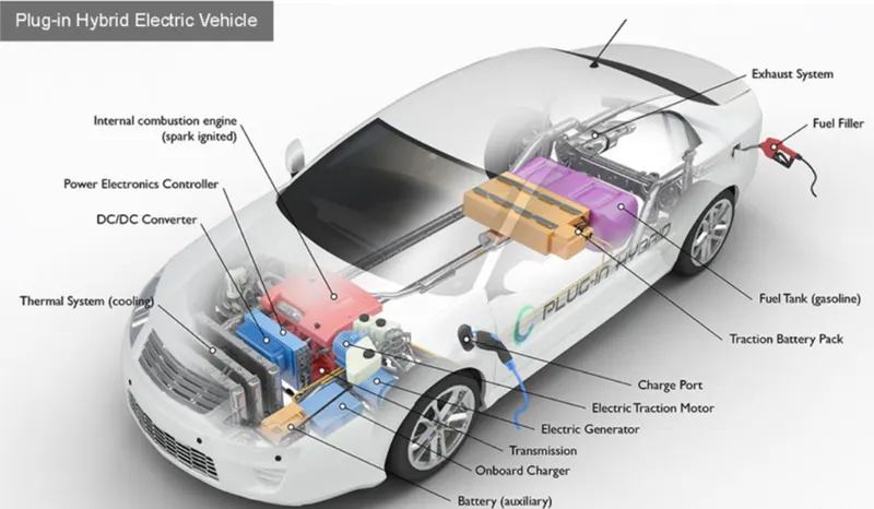
There are two basic types of EVs: all-electric vehicles (AEVs) and plug-in hybrid electric vehicles (PHEVs). AEVs include Battery Electric Vehicles (BEVs) and Fuel Cell Electric Vehicles (FCEVs). In addition to charging from the electrical grid, both types are charged in part by regenerative braking, which generates electricity from some of the energy normally lost when braking. Which type of vehicle will fit your lifestyle depends on your needs and driving habits. Find out which BEVs and PHEVs are available to suit your needs.
EVs (also known as plug-in electric vehicles) derive all or part of their power from electricity supplied by the electric grid. They include AEVs and PHEVs.
AEVs (all-electric vehicles) are powered by one or more electric motors. They receive electricity by plugging into the grid and store it in batteries. They consume no petroleum-based fuel and produce no tailpipe emissions. AEVs include Battery Electric Vehicles (BEVs) and Fuel Cell Electric Vehicles (FCEVs).
PHEVs (plug-in hybrid electric vehicles) use batteries to power an electric motor, plug into the electric grid to charge, and use a petroleum-based or alternative fuel to power the internal combustion engine. Some types of PHEVs are also called extended-range electric vehicles (EREVs).
Electric Vehicle Model :
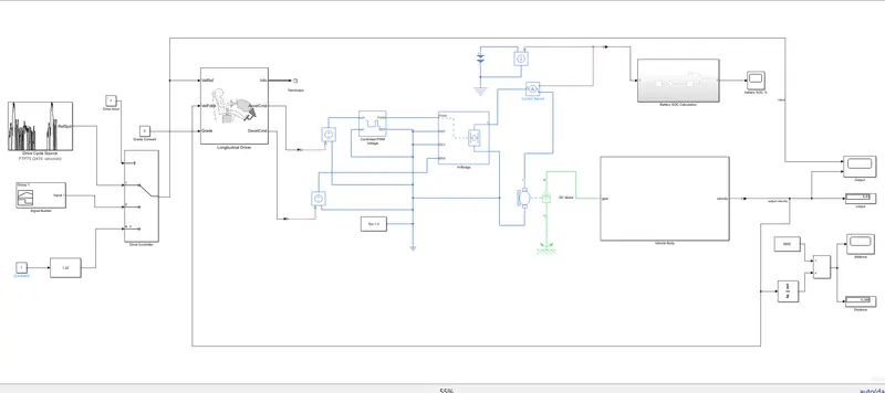
Model parameters :
Modelling of Vehicle Body System :
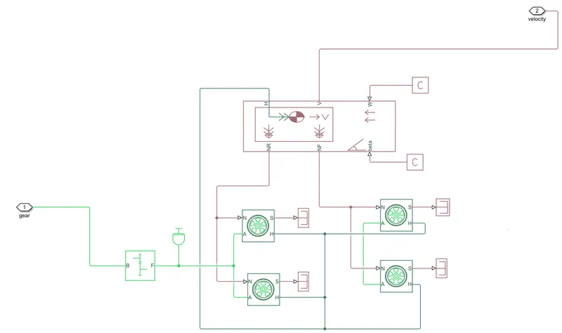
Tire :-
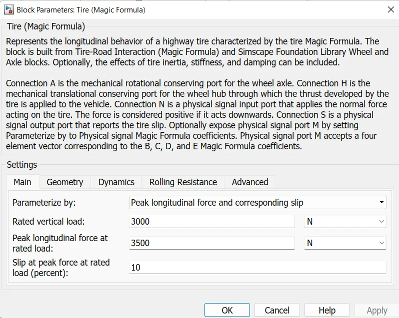
A- Axles [Mechanical rotational port associated with the axle that the tire sits on.]
S- Slip [Physical signal output port associated with the relative slip between the tire and road.]
H- Hub [Mechanical translational port associated with the wheel hub that transmits the thrust generated by the tire to the remainder of the vehicle.]
N- Normal force [Physical signal input port associated with the normal force acting on the tire. The normal force is positive if it acts downward on the tire, pressing it against the pavement.]
These tires are connected to the vehicle body.
Vehicle body :-
The vehicle body has various inputs can be modulated for the vehicle to have a basic setup as it consists of parameters
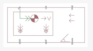
- NR - Normal Force Rear [Physical signal output port for normal force on the rear axle. Wheel forces are considered positive if acting downwards.]
- NF - Normal Force Front [Physical signal output port for normal force on the front axle. Wheel forces are considered positive if acting downwards.]
- H - Horizontal motion[Conserving port associated with the horizontal motion of the vehicle body. Connect tire traction motion to this port.]
- V - Longitudinal velocity,Speed of the vehicle body [Physical signal output port for vehicle longitudinal velocity.]
- Beta - Road incline angle,The grade of the vehicle.[Physical signal input port for road incline angle.]
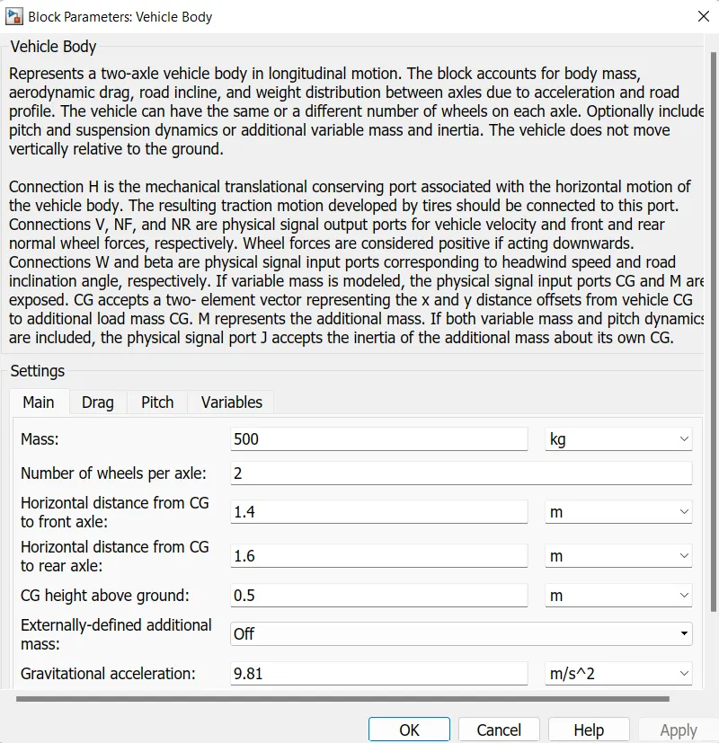
- The vehicle mass ,drag values, pitch values can be varied in the vehicle body parameters.
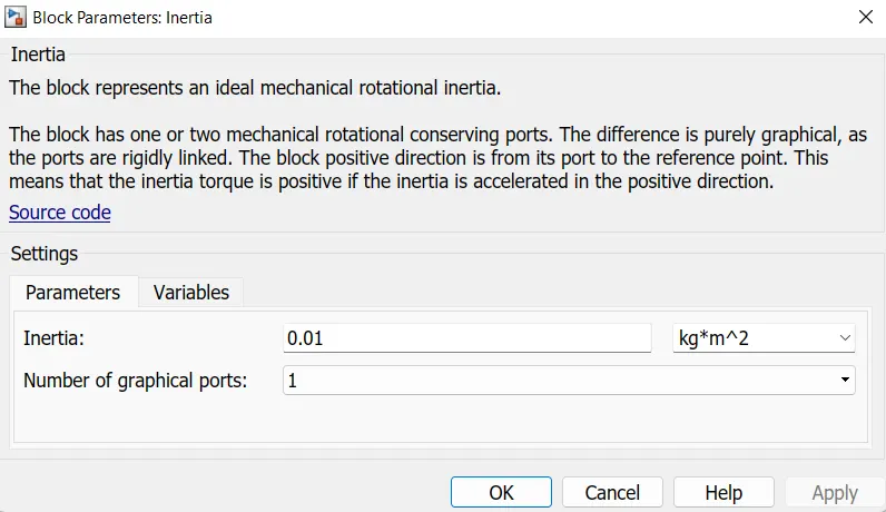
INERTIA:-
This block generally represents the mechanical rotational element.
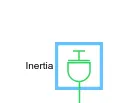
T=J (dw/dt)
Where,
T= Inertia torque
J = Inertia
Ω = Angular Velocity
T = Time
The inertia is connected to the simple gear to find the inertia because of axel and gear are a mechanical rotating devices.
SIMPLE GEAR
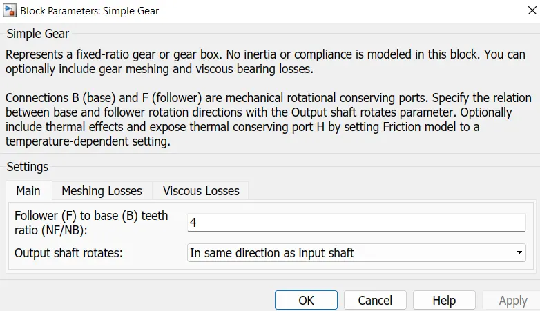
The Simple Gear block represents a gearbox that constrains the connected driveline axes of the base gear, B, and the follower gear F
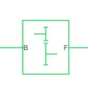
B: The output B,base gear is connected with the input of DC motor R. It is a Rotational mechanical conserving port.
F: The output of F,Follower gear is connected with rear axle.It is also a Rotational mechanical conserving port.
PS constant and PS terminator :-
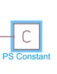

PS constant is used for physical signal input ports W andd beta corresponding to headwind speed and road inclination angle, respectively. Here ps constant value is set to 0.
PS terminator is used to connect physical signal output port S that reports the tire slip.
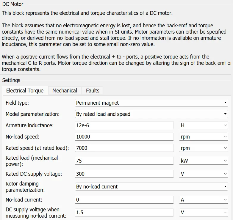
DC Motor:-
The DC Motor block represents the electrical and torque characteristics of a DC motor using the following equivalent circuit model:
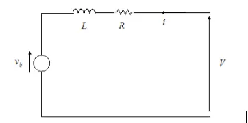
we specify the equivalent circuit parameters for this model when you set the Model parameterization parameter to By equivalent circuit parameters. The resistor R corresponds to the resistance you specify in the Armature resistance parameter. The inductor L corresponds to the inductance you specify in the Armature inductance parameter.
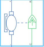
As we see in the above figure it mainly has 2 sides to the block.The Mechanical block is on the right and electrical block is on the left. Mechanical block has 2 ports ,C and R.The C refers to Casing and R refers to the rotor which produces a Torque.The electrical side has a positive and a negative terminal for the Voltages to be applied.If a positive voltage is Electrical conserving port associated with the DC motor.If a negative voltage is Electrical conserving port associated with the DC motor.
Here in this system ,the positive terminal is connected with the current sensor; the negative terminal is connected with the negative terminal of H-Bridge.
R is DC motor rotor which connects with mechanical rotational port where it is simple gear where as C is DC motor case it is connected to the mechanical rotational reference
The mechanical reference block is shown below
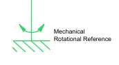
The Mechanical Rotational Reference block represents a reference point, or frame, for all mechanical rotational ports. All rotational ports that are rigidly clamped to the frame (ground) must be connected to a Mechanical Rotational Reference block.
H-Bridge:-
The power converter is needed to provide power of the correct form and magnitude from one component to another.In EV’s a power converter is needed to provide a DC voltage from battery of the EV to DC motor.As mentioned i have used a type of H-Bridge motor drive as my power converter.The block is shown below
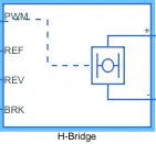
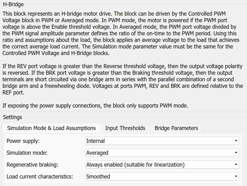
The H-bridge has 2 ports:-the left side is for controlling of voltage signals and the right side for the terminals to provide the controlled voltage of DC motor.The left side ports of the H-Bridge are shown below
- PWM:-This stands for Pulse Width Modulation which will provide the voltage pulses to the H-Bridge either in the PWM or average mode
- REF:-This stands for the Reference
- REV:-This stands for the Reverse
- BRK:-This stands for the Brake
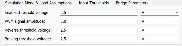
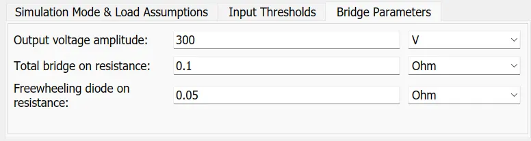
Here PWM output port is connected with PWM input port of controlled PWM voltage.The REF and REV port are connected with REF port of controlled PWM voltage port.The BRK port is connected with a controlled voltage source.
It shows that the Positive terminal is connected to the positive terminal of the current sensor and negative terminal is connected with the negative terminal of the DC motor.
Controlled PWM Voltage:-
The Controlled PWM Voltage block represents a pulse-width modulated (PWM) voltage source. The block is shown below.

Ref+:-Positive electrical reference voltage.
Ref - :-Negative electrical reference voltage
PWM:-Electrical conserving port associated with the pulse-width modulated signal.
REF:-Electrical conserving port associated with the floating zero volt reference
For the Electrical input ports variant of the block, the demanded duty cycle is
100⋅Vref-VminVmax-Vminpercent">100⋅[(Vref−Vmin)/(Vmax−Vmin)]percent
- Vref is the reference voltage across the ref+ and ref- ports.
- Vmin is the minimum reference voltage.
- Vmax is the maximum reference voltage.
The value of the Output voltage amplitude parameter determines amplitude of the output voltage.
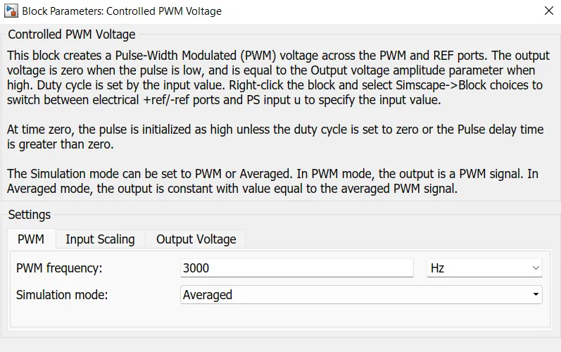
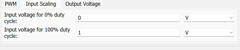

Controlled Current Sensor:-
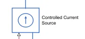
- The Controlled Current Source block represents an ideal current source that is powerful enough to maintain the required current through the voltage across the source
- In the controlled Current sensor,it has two-port connected to the battery and one electrical converting port is connected with the PS-Simulink converter to rate transition block and scope.
- The current sensor is a device that detects and converts current to get an output voltage, which is directly proportional to the current in the designed path.
- When current is passing through the circuit, a voltage drops across the path where the current is flowing. Also, a magnetic field is generated near the current-carrying conductor.
Electrical Reference:-
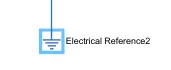
- The Electrical Reference block represents an electrical ground.As it shown below
- Electrical conserving ports of all the blocks that are directly connected to ground must be connected to an Electrical Reference block.
- A model with electrical elements must contain at least one Electrical Reference block.
- In this we had connected the electrical reference for the battery and motor etc..
Controlled Voltage Source:-
The Controlled Voltage Source block represents an ideal voltage source that is powerful enough to maintain the specified voltage at its output regardless of the current flowing through the source.The block is shown below
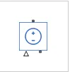
The output voltage is V = Vs, where Vs is the numerical value presented at the physical signal port.
The block has one physical signal input port and two electrical conserving ports associated with its electrical terminals.
Solver Configuration:-
The Solver Configuration block specifies the solver parameters that your model needs before you can begin simulation.The Block is shown below.

The block has one conserving port. You can add this block anywhere on a physical network circuit by creating a branching point and connecting it to the only port of the Solver Configuration block.
It is connected with the controlled PWM voltage and for a model only one solver configuration is connected.
Battery:-
The Battery block represents a simple battery model.The Battery model is shown below.
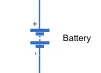
- If we select Infinite for the Battery charge capacity parameter, the block models the battery as a series resistor and a constant voltage source.
- If we select Finite for the Battery charge capacity parameter, the block models the battery as a series resistor and a charge-dependent voltage source.
- In the finite case, the voltage is a function of charge and has the following formula is mentioned as
V=Vo(SOC/[1-β(1-SOC)])
Where
- SOC (state-of-charge) is the ratio of current charge to rated battery capacity.
- V0 is the voltage when the battery is fully charged at no load, as defined by the Nominal voltage, Vnom parameter.
- β is a constant that is calculated so that the battery voltage is V1 when the charge is AH1.
The connection of the battery is as follows,the negative(-)terminal is connected to the ground and then controls the current source physical port to the positive direction which indicates the flow of current.
The positive (+) terminal is connected to the controlled current source of electrical conserving ports.
State Of Charge (SOC) calculation :-
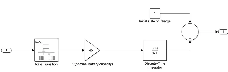
- The input for this block is from the current sensor.
- Now this signal is connected to the rate transition block.This handles the transfer of data between blocks operating at different rates. The block and its parameters are shown below,
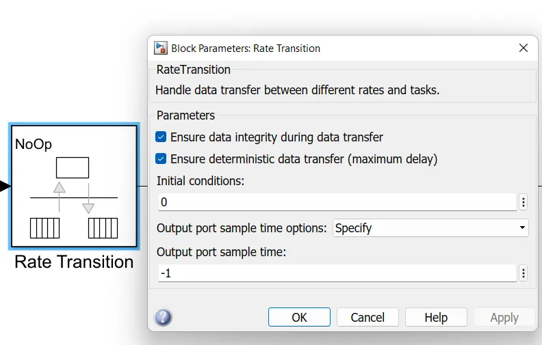
Then a gain block is connected to it. This gain will multiply the value of k =1/(A.sec),
where A.sec is the ampere second value of the battery.
In this case the battery capacity is in A.hr, which is ampere hour.
To convert,
A.sec = A.hr.(3600)
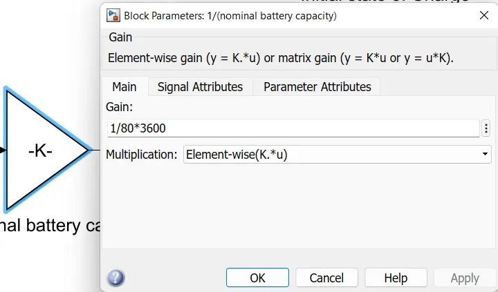
The Gain block multiplies the input by a constant value (gain). The input and the gain can each be a scalar, vector, or matrix.
Here Gain Value is the multiplication element and the input is 1/80*3600,where 80 is the battery ampere and 3600 is second.
Then to add all thesse values with respect tio time, we have used a Discrete-time integrator block. This block will accumulate the input signal.
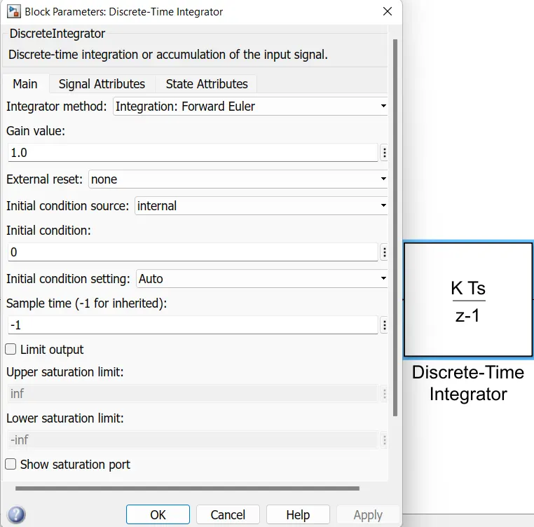
Now this summed value is subtracted from 1, which will give us the remaining state of charge.
Sum Block:-

The Sum block performs addition or subtraction on its inputs.
In this block,the negative terminal will be connected with the discrete-time integrator and positive terminal with a constant.
PS-Simulink Converter:-

- The PS-Simulink Converter says about connecting the physical signal to the simulink signal. We use this block in the system to connect mostly scopes like physical signals to the simulink signal or simulink scope.
- For Calculating the SOC we have to use Subsystems to connect different parameters like Rate transition,Gain block,Discrete Time Integrator,Constant and Sum block.
Longitudinal Driver:-
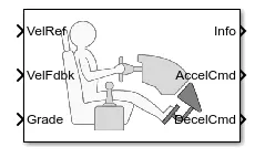
The Longitudinal Driver block implements a longitudinal speed-tracking controller. Based on reference and feedback velocities, the block generates normalized acceleration and braking commands that can vary from 0 through 1.
The different types are
- VelRef:-Reference velocity, vref, in m/s.
- VelFdbk:-Longitudinal vehicle velocity, U, in the vehicle-fixed frame, in m/s.
- Grade:-Road grade angle, θ or γ, in deg.
- Info:-Bus signal containing these block calculations.
- AccelCmd:-Commanded vehicle acceleration, yacc, normalized from 0 through 1.
- DecelCmd:-Commanded vehicle deceleration, ydec, normalized from 0 through 1.
The inputs parameters are given below:-
- Control Type:-PI is a Proportional-Integral (PI) Control with tracking windup and feed-forward gains.
- Reference and Feedback unit:- m/s
Discussing about Connection:-
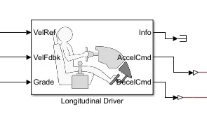
- VelRef:-Reference vehicle velocity is connected with speed result block.its units is m/s.
- VelFdbk:- Longitudinal vehicle velocity is connected with an integrator block for continuous-time integration of the VelFdbk signal.
- Grade:- Road grade angle is connected with constant block is 0.
- Info:-Bus signal,Here we have used the signal to terminate the signal block.
- AccelCmd:-Commanded vehicle acceleration is connected with controlled voltage source input signal by combination with PS-Simulink Converter.
- DecelCmd:-Commanded vehicle deceleration is connected with another controlled voltage source signal by combination of PS-Simulink converter.
Drive Cycle controller :-
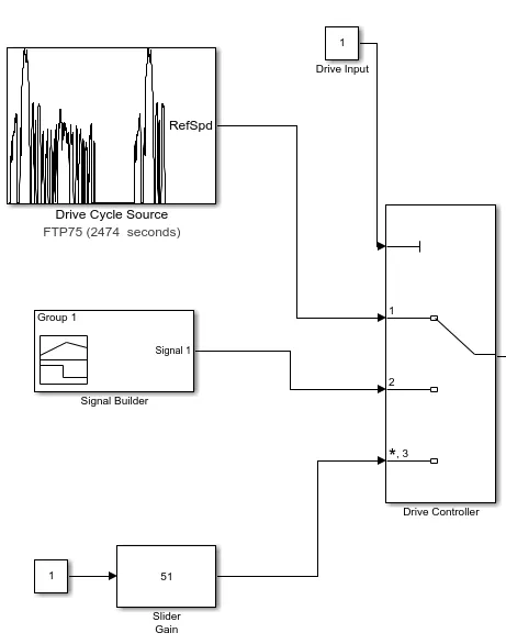
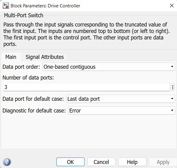
Multi-Port Switch is used select our desired input to the drive reference signal to longitudinal Driver block. Constant block is used to select option from the multi-port switch block.
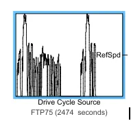
Drive Cycle Source:-
The Drive Cycle Source block generates a standard or user-specified longitudinal drive cycle.
In the model i have used FTP75 Drive Cycle Source.The drive cycle source is given below
The output plotted the model for FTP75 Model is
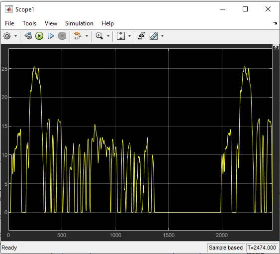
The block output is the specified vehicle longitudinal speed, which we can use to:
- Predict the engine torque and fuel consumption that a vehicle requires to achieve desired speed and acceleration for a given gear shift reference.
- Produce realistic velocity and shift references for closed loop acceleration and braking commands for vehicle control and plant models.
- Study, tune, and optimize vehicle control, system performance, and system robustness over multiple drive cycles.
2. Signal builder :-
Signal builder block is used as another drive cycle input to the multi-port block. Using signal builder block we can create our own signal level.
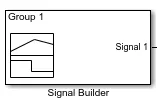
3. Slider gain :-
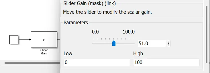
Slider gain block is used as another drive cycle input to the multi-port block. Using slider gain block we can vary the speed , like we accelerate/deaccelerate throttle of the vehicle.
Results :-
These are the model details which would be simulated and the results are as follows:-
Output 1 : FTP75 Drive Cycle Source.
Scope 1:- The Velocity feedback and the Drive Cycle Source
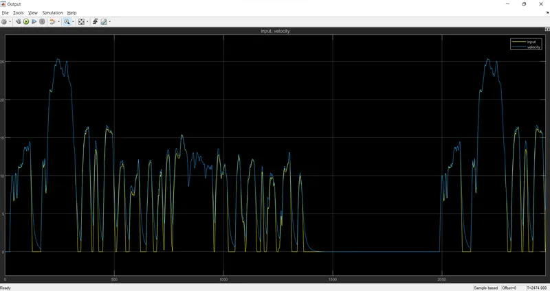
- Here PS Simulink converter (Yellow line) is our drive cycle source output and Multiport switch (Blue line) is input given as drive cycle (FTP75) which vehicle tries to match with input drive cycle with EV model and its parameters.
Thus from above result, we can see that Vehicle speed output almost matches with reference speed input with small deviation due to vehicle inertia and its control parameter.
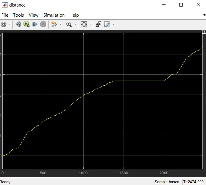
Distance :-
The overall distance travelled by the vehicle 5.38 kms in a duration of 2474 seconds.
Battery SOC Scope :-
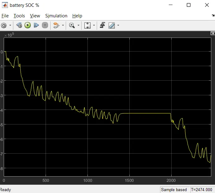
It is noted that the charge of the battery started from initial level and during the operation of the vehicle for 2474 seconds using the FTP75 Drive cycle.
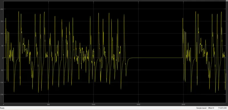
From the above output we observe that the decreasing of the battery charge leads to the regenerative braking and the increasing of the battery charge leads to the dynamic braking. The current stays constant as no power is applied on the vehicle.This can be seen from above result like sometimes SOC (State Of Charge) spike starts increase.
Current Sensor :-
Current from the H-bridge and DC motor is measured.
Output : 2 - Signal Builder source.
By selecting signal builder source as input we can run the vehicle in our own desired value and calculate the values.
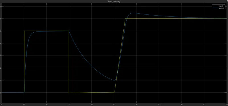
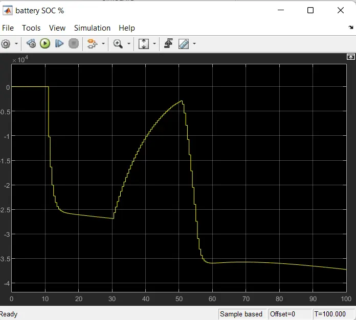
Here, the vehicle was run for 100 seconds for pre-defined signal builder input.
Battery SOC Scope :-
Output : 3 - Slider gain source.
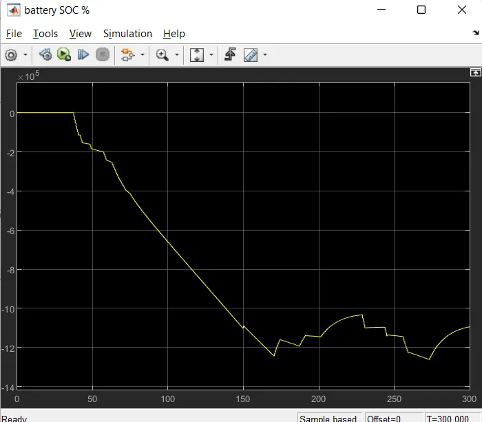
Using slider gain block as a source we can control the input same like throttle control with us by accelerating and deaccelerate the input and vary the speed.
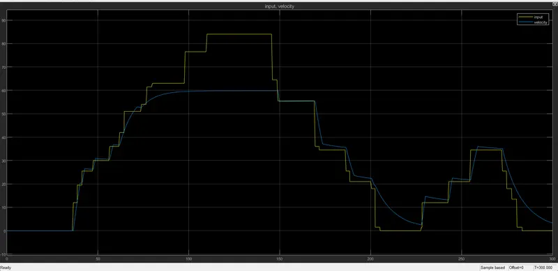
Here the vehicle is runned for 300 seconds by varing the slider gain value.
Battery SOC Scope :-
Current Sensor :-
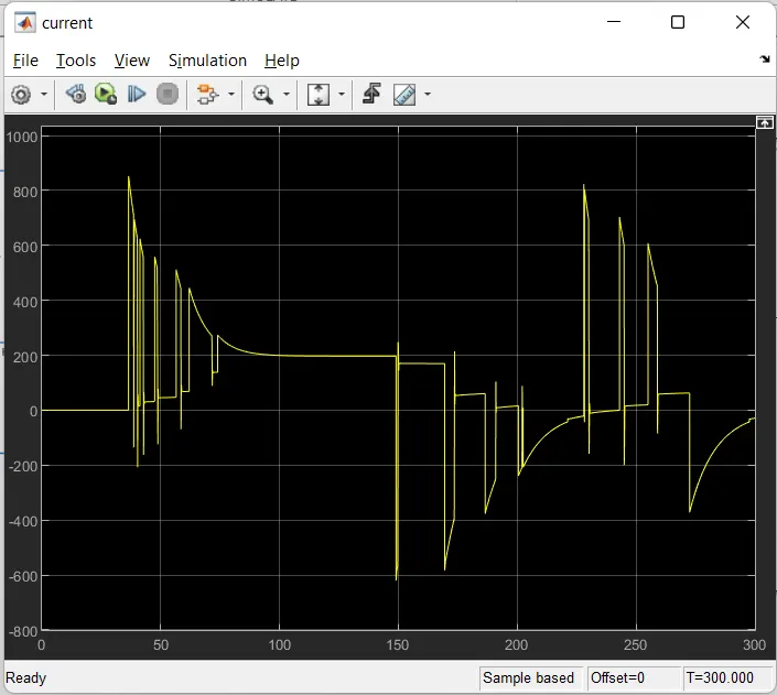
Current is varied according to the change in the slider gain input value and current value is measured in ampere.
Conclusion:
Thus MATLAB model Electric Vehicle is built sucessfully using the respective blocks with DC motor and a battery. And we obtained output by using FTP75 Drive Cycle Source and other sources as input to the vehicle.