Final Project: Design of an Electric Vehicle
EV LIVE BATCH
Objective: Design of an electrical vehicle
SIMULINK MODEL:
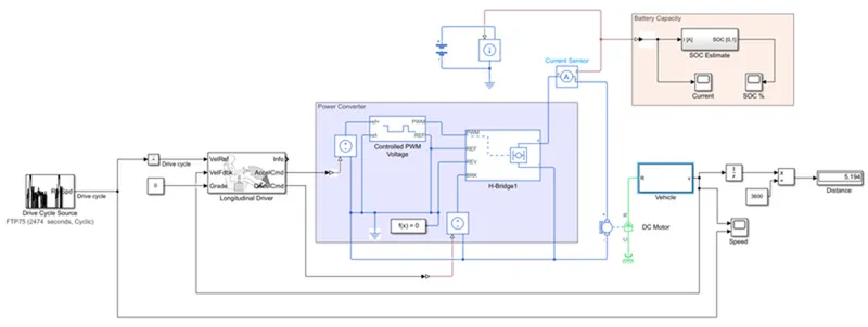
The blocks comprising the model are explained below:
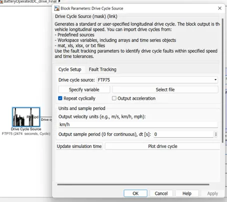
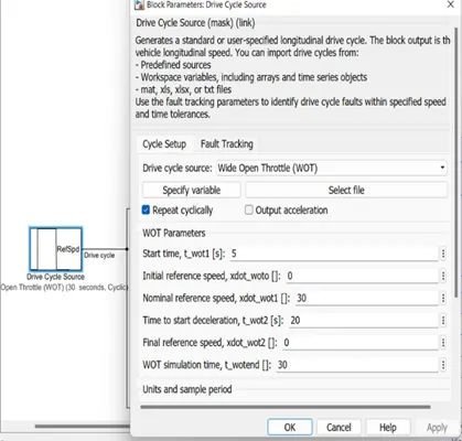
- Drive Cycle Source - The Drive Cycle Source block generates a standard or user-specified longitudinal drive cycle. The block output is the specified vehicle longitudinal speed. For our model, we have selected two different cycles, FTTP & WOT drive cycle.
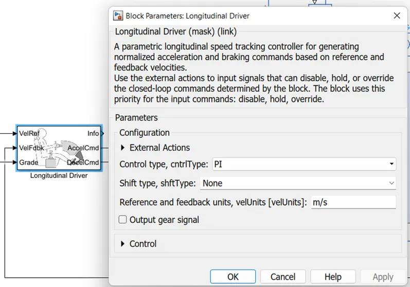
- Longitudinal Driver - The Longitudinal Driver block implements a longitudinal speed-tracking controller. Based on reference and feedback velocities, the block generates normalized acceleration and braking commands that can vary from 0 through 1. You can use the block to model the dynamic response of a driver or to generate the commands necessary to track a longitudinal drive cycle.
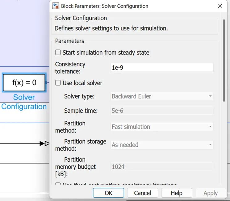
- Power Controller – I’ve marked the area, this area consists of many blocks grouped together, two controlled voltage source, controlled PWM Voltage, H-Bridge., solver configuration.
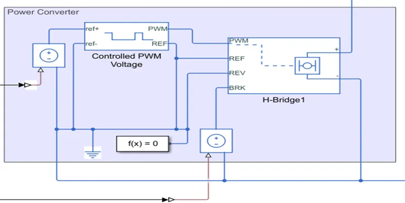
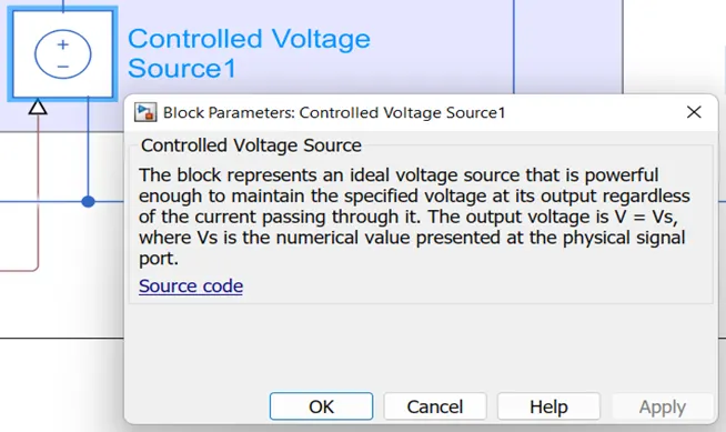
- Controlled Voltage Source - The Controlled Voltage Source block converts a Simulink®input signal into an equivalent voltage source. The generated voltage is driven by the input signal of the block.
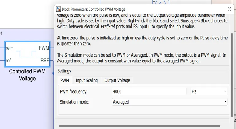
- Controlled PWM Voltage – The Controlled PWM Voltage block represents a pulse-width modulated (PWM) voltage source. You can model electrical or physical signal input ports by setting the Modeling optionparameter to either:
Electrical input ports — The block calculates the duty cycle based on the reference voltage across its ref+ and ref- ports. This option is the default.
PS input — Specify the duty cycle value directly by using an input physical signal port.
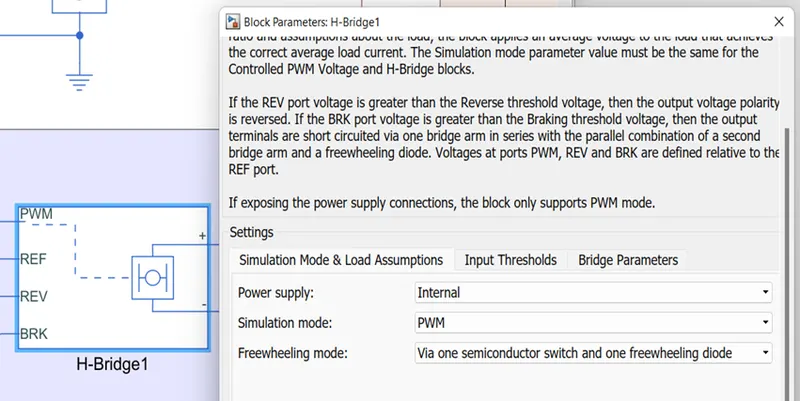
- H- Bridge – This block represents an H-bridge motor drive. The block can be driven by the Controlled PWM Voltage block in PWM or Averaged mode. In PWM mode, the motor is powered if the PWM port voltage is above the Enable threshold voltage. In Averaged mode, the PWM port voltage divided by the PWM signal amplitude parameter defines the ratio of the on-time to the PWM period. Using this ratio and assumptions about the load, the block applies an average voltage to the load that achieves the correct average load current. The Simulation mode parameter value must be the same for the Controlled PWM Voltage and H-Bridge blocks.
- Solver Configurtion – It defines solver settings to use for simulation
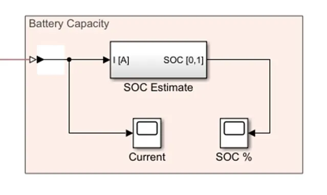
- Battery Capacity Area: This area is marked to show the SOC Estimate, that is it shows how the battery capacity drains when the motor is operated for the required drive cycle.
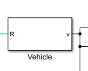
Vehicle – it is a substation block, which consists of the vehicle parameters that include the vehicle dimensions, tire dimensions, and gear ratio.
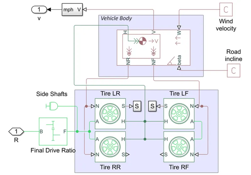
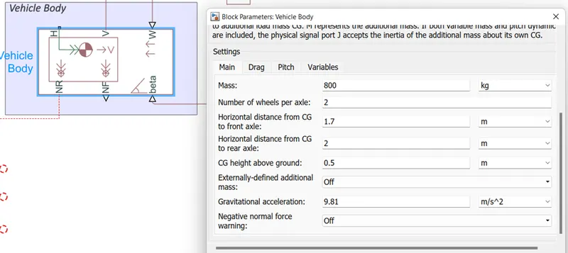
- Vehicle body – Represents a two-axle vehicle body in longitudinal motion. The block accounts for body mass, aerodynamic drag, road incline, and weight distribution between axles due to acceleration and road profile. The vehicle can have the same or a different number of wheels on each axle. Optionally include pitch and suspension dynamics or additional variable mass and inertia. The vehicle does not move vertically relative to the ground.
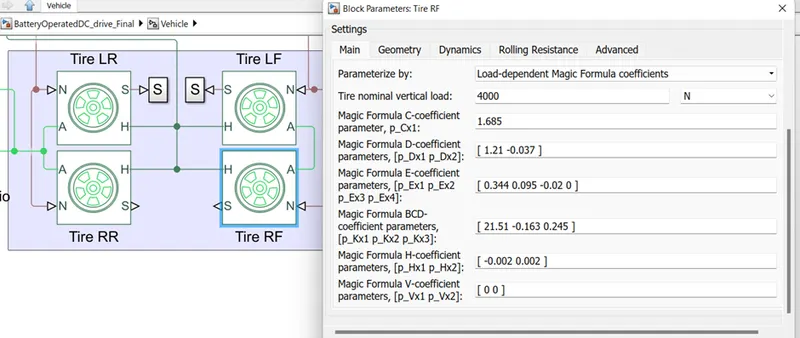
- Tire - Represents the longitudinal behaviour of a highway tire characterized by the tire Magic Formula. The block is built from Tire-Road Interaction (Magic Formula) and Simscape Foundation Library Wheel and Axle blocks. Optionally, the effects of tire inertia, stiffness, and damping can be included.
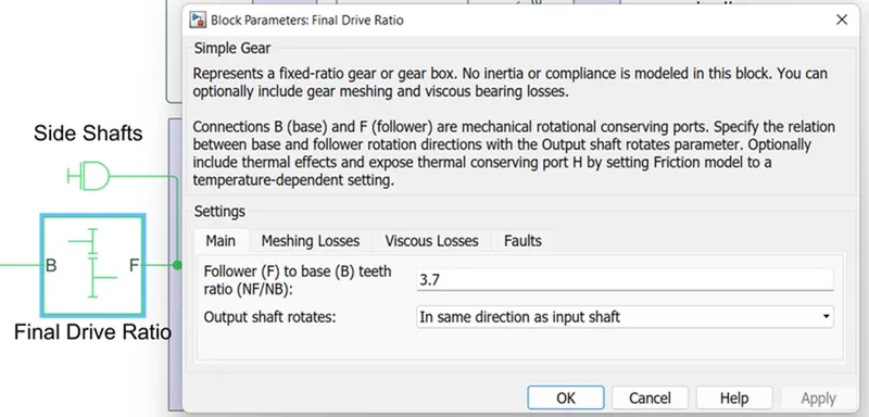
- Gear Ratio – Represents a fixed-ratio gear or gear box. No inertia or compliance is modeled in this block. You can optionally include gear meshing and viscous bearing losses.
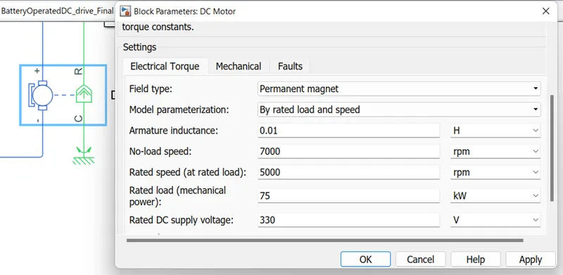
- DC Motor - This block represents the electrical and torque characteristics of a DC motor. The block assumes that no electromagnetic energy is lost, and hence the back-emf and torque constants have the same numerical value when in SI units. Motor parameters can either be specified directly, or derived from no-load speed and stall torque. If no information is available on armature inductance, this parameter can be set to some small non-zero value.
After joining the blocks as shown in the SIMULINK MODEL, we run the model two times, for different drive cycles and see the results.
RESULTS:
For FTP Drive cycle:
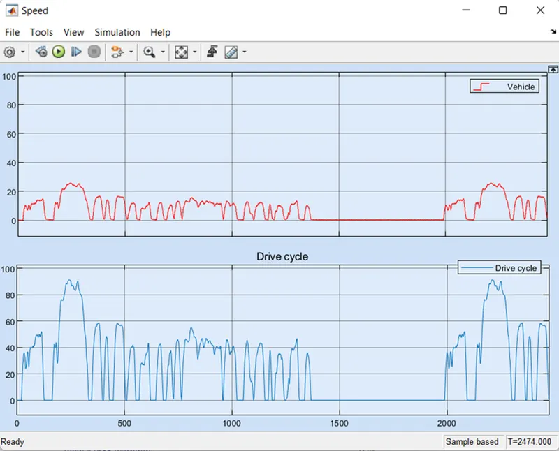
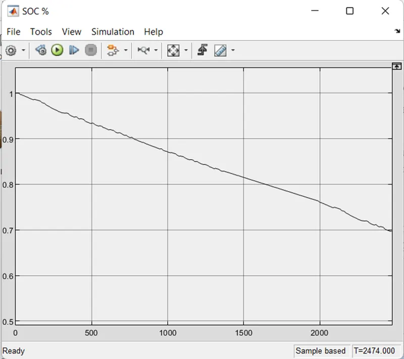
For WOT drive cycle:
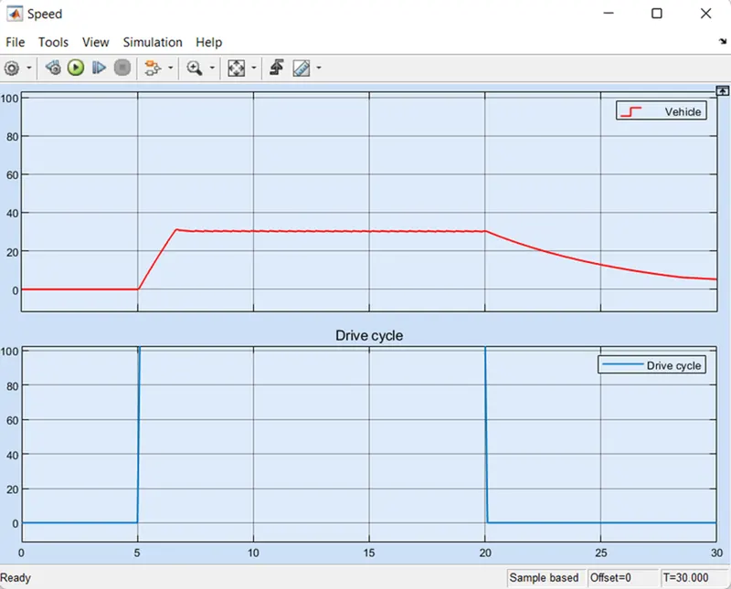
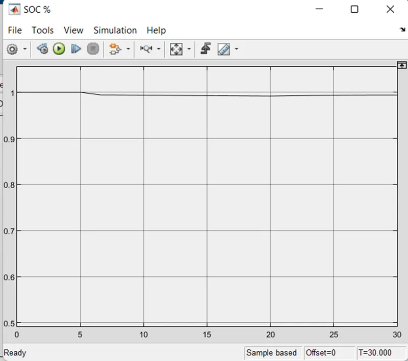
CONCLUSION:
This is how the electric vehicle is created by MATLAB SIMULINK
EV has obtained an output according to the FTP75 drive cycle and it can tested for any drive cycle by selecting in the drive cycle block. It has travelled 5.5km by the present battery capacity, if we increase the battery capacity to higher we can travel more distance but in the real time this should be done by considering the space and cost.