Final Project: Design of an Electric Vehicle
Aim:-Is to prepare the Car with a Li-ion battery.
Background theory:-
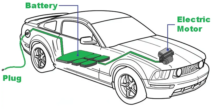
Here the car will work ultimately work on the battery car.
And it will have these features.
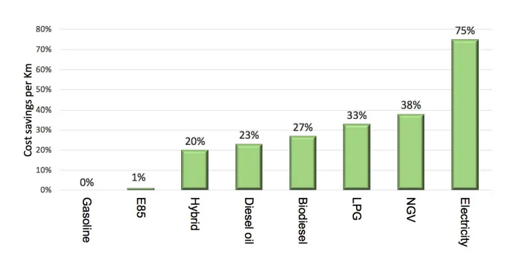
Fig1:Cost savings per km
here it will be clear that the electricity will be one of the cheapest operational costs and the savings will be around 75%
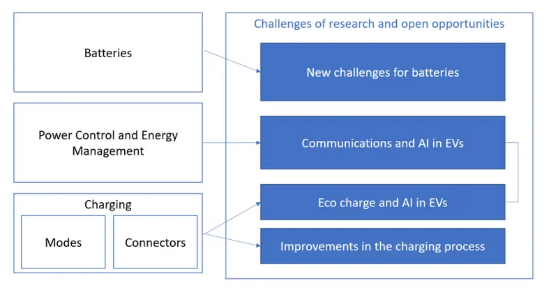
Fig2:Topics in the EV world
and the main r and d will be happening in the Battery field.
Then after charging of power control and energy management and the saving could be done from modes and connectors.
so all of the EV could be done in AI.
communication is done in CAN communication.
Features of BESS are Battery Electric Vehicles (BEVs): vehicles 100% are propelled by electric power. BEVs do not have an internal combustion engine and they do not use any kind of liquid fuel. BEVs normally use large packs of batteries in order to give the vehicle acceptable autonomy. A typical BEV will reach from 160 to 250 km, although some of them can travel as far as 500 km with just one charge. An example of this type of vehicle is the Nissan Leaf, which is 100% electric and it currently provides a 62 kWh battery that allows users to have an autonomy of 360 km.
EV sales
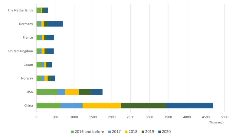
Fig3:-Sales of EV
in the entire world and the china will have more number of sales.The reason will be we can get the li in china.
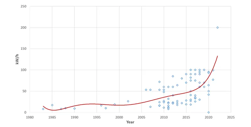
Fig4:-Li-ion battery energy storage capacity
The model which we had prepared
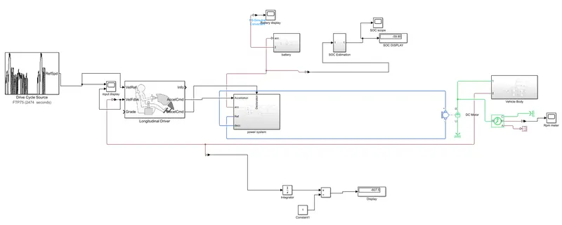
Fig5:Model of Li-ion battery is fixed to DC motor.
It will have this sub-block
- Drive cycle
- Longitudinal driver
- Power system
- Battery
- SOC estimation
- Vehicle body
- DC motor
- scope
Drive cycle:-
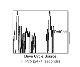
Fig6:Drive cycle sources
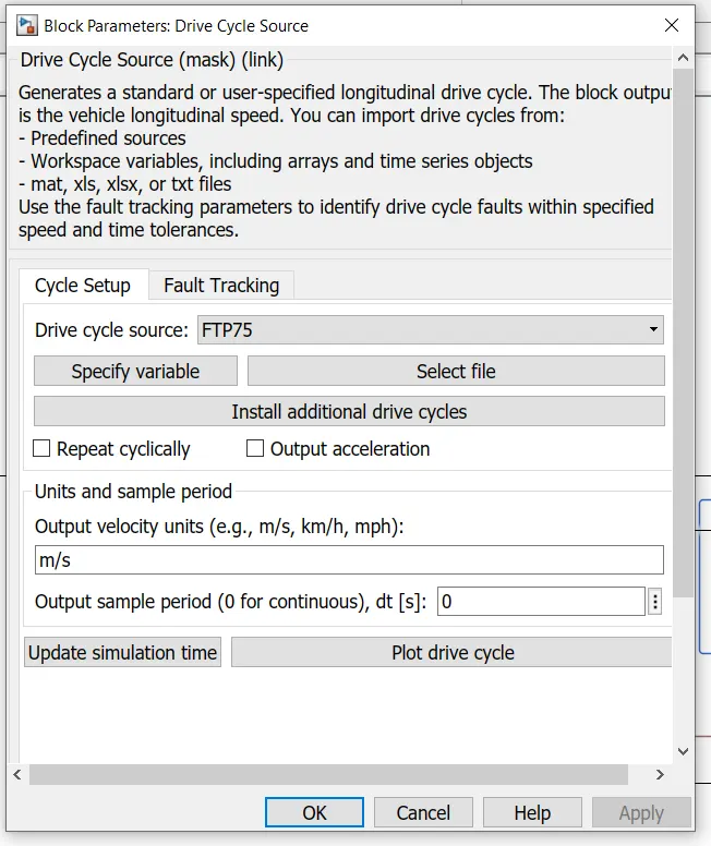
Fig 7:initial data of Drive cycle block
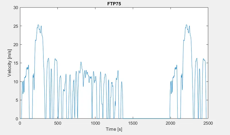
Fig8:-FTP 75 drive cycle
Now here we had given input as FTP 75 which is a federal cycle and 75 is the version name. And in this block, we got the time versus velocity graph. The answer we are going to except for this block.
Input scope
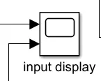
fig9:-scope
Here we going to see the input drive cycle and the feedback from the vehicle body which we are going to get from a vehicle.
Longitudinal Driver
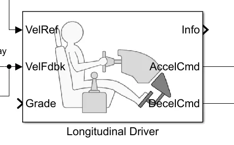
Fig 10:Longitudinal Driver Block
here it is block and it will happen as an driver and it hill have 6 port
- ValRef:-this is an refreance of input
- VelFdbk:this is one power which will feedback on from vehicle
- Grade:- when you need to climb hill of going to down hill you can have.
- info:-this will have ant thing will be given or it need to be grounded
- AccelCmd:-this will give the acceleration from the driver
- DecelCmd:-This will giving Deaccleartion
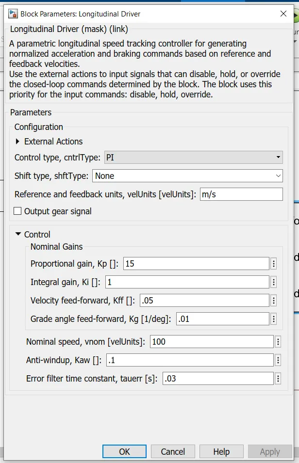
Fig11:-Initial parameters of Driver block
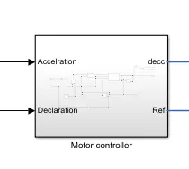
Fig 12:-motor controller block
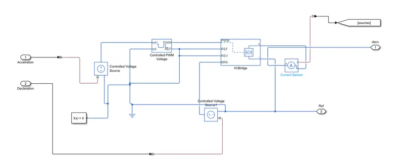
Fig13:-Motor controller subsystem view
now here we need to consider the input from acceleration and declaration
then 1 acceleration is given through Controlled voltage sources and output will be given to ref+ and another end will be grounded.
grounded will be common grounded and we had given solver configuration.
another input will be given to Controlled Voltage Sources and it has 2 input and 2 output
+ ref and ground then the output will have pmw with and ground
pwm:-here input will be in the form of pmw width andall
Ref:it will get the output in form of ref voltage
Rev:-this will work as per rev voltage
Brk:-this will work in reverse voltage with reverse voltage.
The output will be + and - and we had connected the dc voltage.
and it is given through current sources.
this will give output in pmw wave as per input
this output will be connected to the H bridge
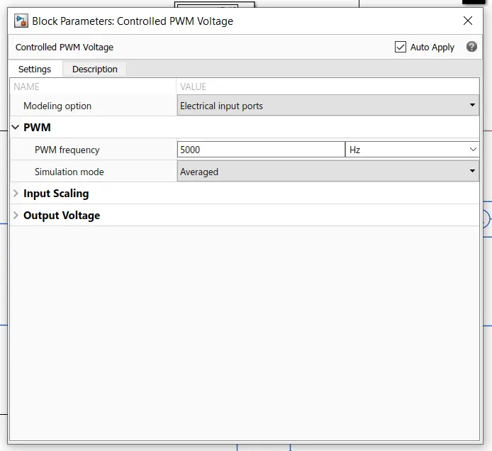
Fig 12:-PMW block
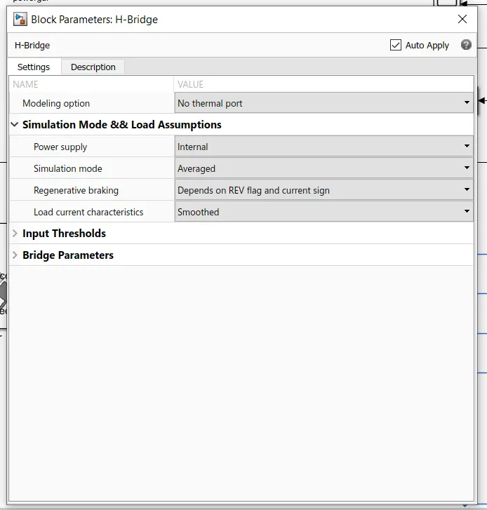
Fig 13:-H bridge block
DC motor
It is a motor and which will convert Electrical power into mechanical power (angular rotation)
here we had considered a motor without any physical and thermal port.
and the output one side is grounded and another side is given input to the simple gear box by which it will work.
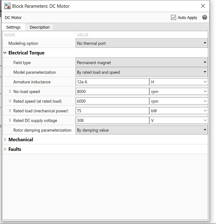
Fig 14:-DC motor block
Simple gear
it will have 2 gear system and it will work on the increase or decrease the torque system as required
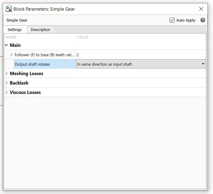
Fig 15:-Simple gear block
The direction of both primary and secondary will be the same
Vehicle Body
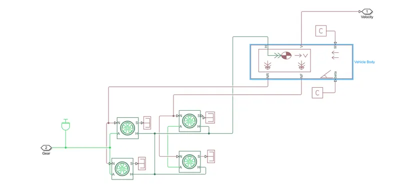
Fig 16:-Vehicle Subsystem
it will have Inertia Block
this we need to ground the inertia and that will be excess or we need not provide the correct inertia.
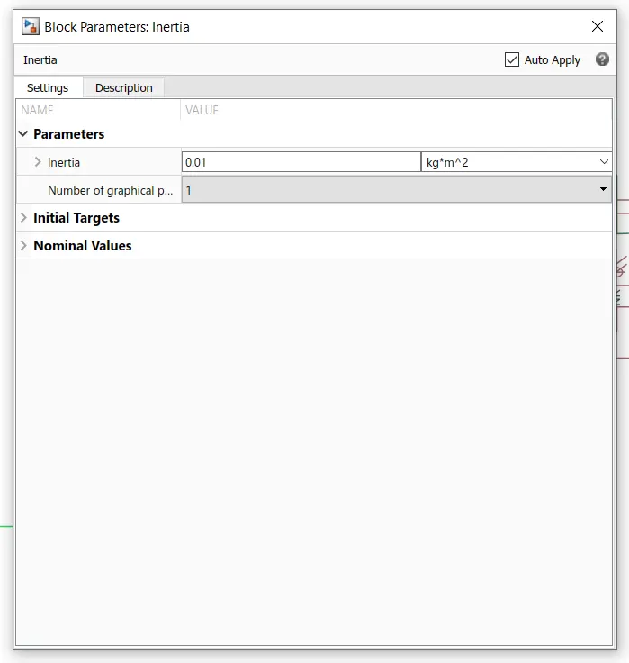
Fig 17:-Inertia block
vehicle Body
this block will account for the aerodynamics of the vehicle and it will work for inertia and all.
it will have six ports namely
H:-We need to make a common point ad we need to connect it with wheels.
V:-This is nothing but velocity we need to make a constant.We had given it like 1
W:-this is used to get elevation and all. Here we had given it as 1 .
NR:-here we had considered it as a reverse wheel and we had made a common point
NF:-this is a forward point and we have made a common point and we had given it as forwarding POINT.
Beta:-this is typically an elevation.
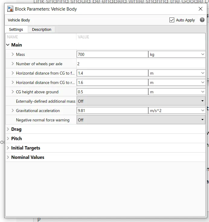
Fig 18:-Vehicle body block
wheels
it has 4 ports namely
N:-signal input port
A:-Mechinial rotation port
S:-Physical output
H:-mechanical translational port
we had parametrized as shown below
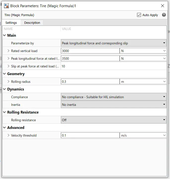
Fig 18:-Vehicle body block
Battery and its associated units
battery
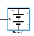
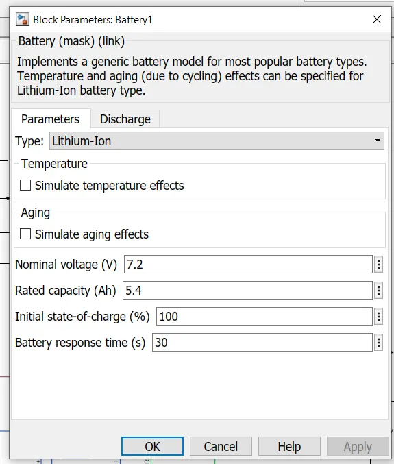
Fig 19:-Li-ion battery block
here we had considered the li-ion type of battery and we had given it as 7.2 V and 5.4 Ah battery
initial soc would be 100 %
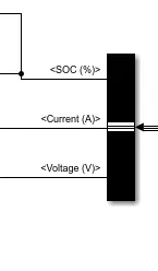
so to check output we had utilized a de mux and we had taken 3 outputs they are
SOC
Voltage
Current
and we had taken output and we had displayed the result and we had taken the scope.
Working of system
- we had given initial sources and we had taken FTP 75 cycle
- then it will come to the driver and in this block, it will convert it into acceleration and deceleration
- before that, we had taken as sources to check both of the input and feedback
- output it gave to the PWM block and this is through a current-controlled sources
- next output is given input to the H bridge
- the output of the H bridge is connected to the dc motor
- here we had given two current-controlled sources
- 1 is for acceleration and another 1 de-acceleration
- for power we had considered Li-Ion battery sources this will work as per the given input which is the output of the H bridge.
- next DC motor we had considered and we had modelled it as 75 kW motor.
- output is given as Vehicle body
- and wheels we had modelled.
- and output we had taken for feedback.
Result Analysis
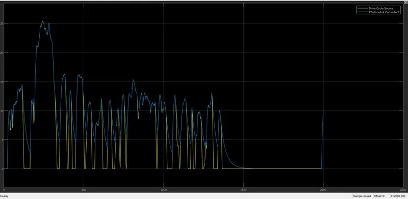
Fig 20:-Initial drive cycle and feedback
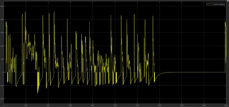
Fig 21:-Current output
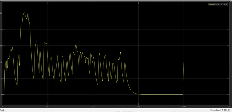
Fig 22:-Feedback output
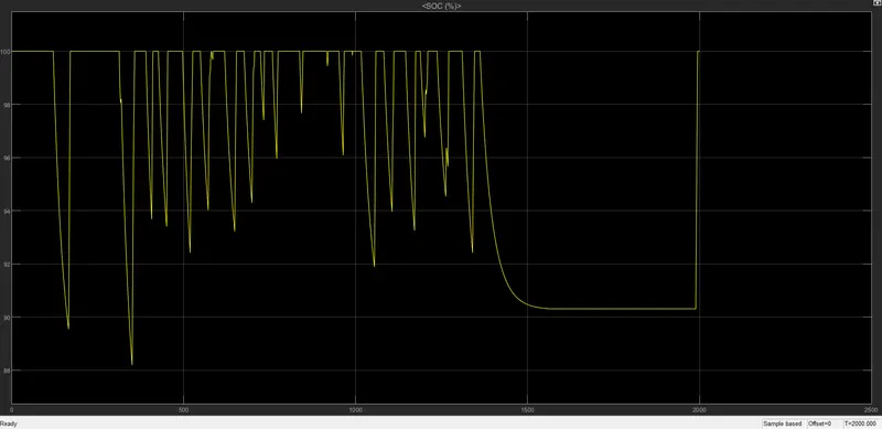
Fig 23:-Soc of battery
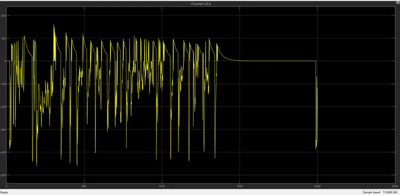
Fig 24:-Current of battery
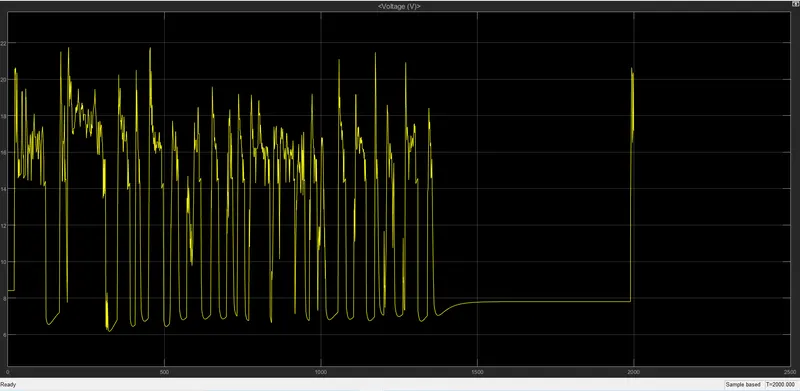
Fig 25:-Voltage of battery
Conclusion:
- now here we can see that both input and the output were more or less it is in the same phase.
- current is more or less the same as the input
- and here had used a block and the vehicle will work and the same acceleration and deceleration will work on the same input.
- here the output of the current will be the same as that of the output.
- Here soc value will start to decrease and then it will get back to the value 1000 s and it will reduce and then also it will get back to its initial value.
- the voltage will start from 6 v and will have spikes and till 22V and lot of spikes and all will be there and it will on that dc motor charismatics, And it will work exactly same as motor input.
- Current will depend upon the load and here we had taken a motor of 75Kv and load and all will be around 1200kg+800kg .
- Current will be varied till 22A till 6A in a positive cycle.