Final Project: Design of an Electric Vehicle
EV LIVE BATCH 16 STUDENT
AIM:
To Create a MATLAB model of electric car which uses a battery and a DC motor. Choose suitable blocks from Powertrain block set. Prepare a report about your model including following:
Objectives:
1. System level configurations
2. Model parameters
3. Results
4. Conclusion
Block Diagram Of Electric Vehicle.
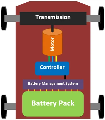
Vehicle Body Consists of Wheels and Gears.
DC Motor is used for vehicle Propulsion.
Let us Consider a Simple Battery.
Used 4 Quadrant switches as Power converter.
Control unit consits of PWM modulation of DC voltage and Longitudinal Driver
SIMULINK Model Of Electric Vehicle:
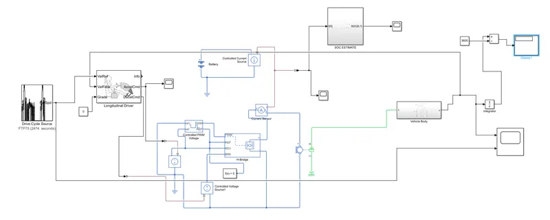
Power Train Block sets used in Simulink:
Vehicle Body: Complete vehicle body is considered as Subsystem as shown below
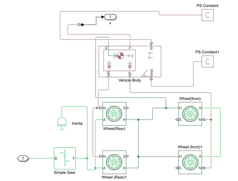
- Wheels: This Block represents the physical Wheel properites of a vehicle Specified by tire manufacturer.
Four Wheel(2 for rear axle and 2 for front axle) Blocks are used and Each one has same specifications..
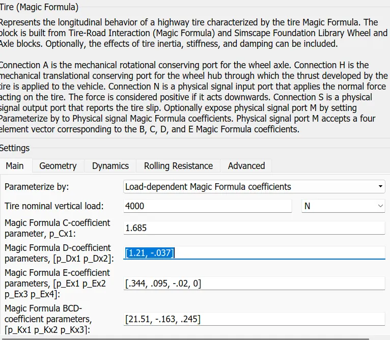
- Wheel Blocks values are considered by default without any changes in all Parameters.
If wheel parameters are specified then that will certainly effects the vehicle performance.
Ports:
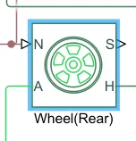
N-Normal Force: This Input Port is used for Force to be applied on Wheel.
Front Wheels N-Port is connected toNF port of vehicle Body.
Rear Wheels N-Port is connected toNR port of vehicle Body.
S-Slip:Physical signal output port associated with the relative slip between the tire and road.
A-AXLE: This Mechanical Translational Port gives Mechanical link between two wheels.
Both Rear and Front Wheels are connected through A-Port.
H-HUB: Mechanical translational port associated with the wheel hub that transmits the thrust generated by the tire to the vehicle body( maintain same speed in all wheels).
All H-Hub ports of Wheels connected to H-port of Vehicle Body.
2.Vehicle Body: This Block gives the Vehicle Body Parameters to be set measured by Physical Vehicle.
In simulation all Parameters are considered as default to reduce simulation time
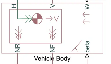
- H,NR and NF ports are connected to Wheels Ports of vehicle.
beta port gives the vehicle body Inclination to the ground in Radians.
W-PortGives the wind velocity applied on front of the Vehicle body(Headwind Speed in m/s).
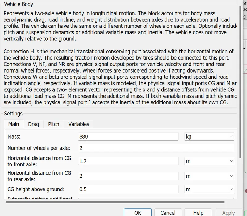
-
Parameters that have given in vehicle body is shown above figure
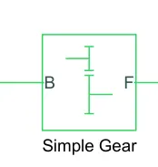
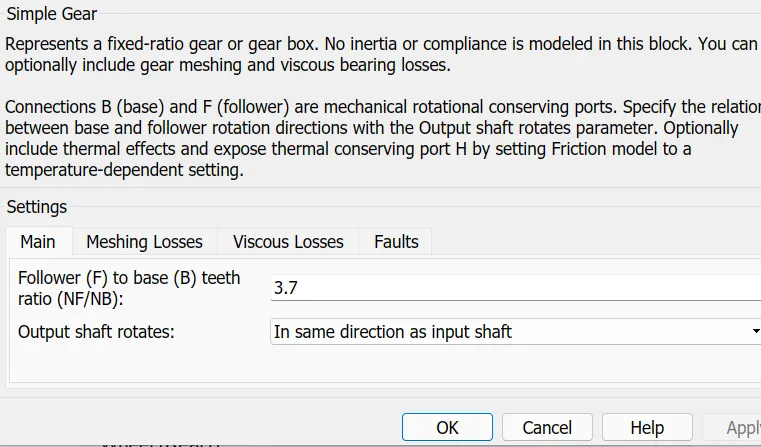
3.GEAR: Represents a fixed-ratio gear from Base(B) to Follower(F).
Gear Ratio is specified by 3.7
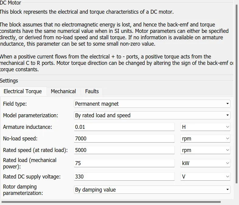
4.DC Motor: This Block represents the electrical and torque characteristics of DC Motor.
Motor Parameters are set as:
No load speed of vehicle=7000 RPM
Rated Load Speed vehicle=5000 RPM
Rated Voltage =330 V
Rated Load of vehicle =75 KW
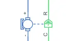
- Remaining all other Parameters( Resistance,Inductance,EMF) are set as Default.
- Blue Part represents electrical Connection to Battery.
- Green part Represents Mechanical Part to be connected to shaft of Gear.
- R-Port is connected to B-Base port of Gear.
- C-Common port is connected to mechanical rotational reference frame.
5.References:
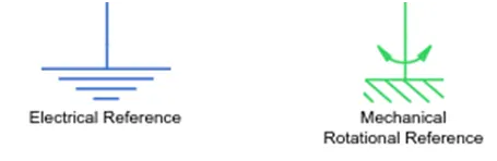
Electrical Reference : Gives the Nuetral Point to the electrical Circuit.
Mechanical Rotational Reference: This Block is considered as a rigid base (ground/frame) point of mechancial body.
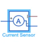
Current Sensor: Sense the current taken by DC Motor and gives the feedback to Battery.
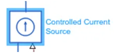
Controlled current Source : Maintain required amount of current to flow from the battery which is sensed from current sensor.
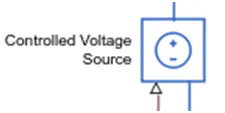
Controlled Voltage Source: Maintain Required amount of voltage to be maintain across DC motor which takes voltage level signal from driver.
PWM: If the input signal has a value greater than the Enable threshold voltage parameter value, the H-Bridge block output is on and has a value equal to the value of the Output voltage amplitude parameter.
If it has a value less than the Enable threshold voltage parameter value, the block maintains the load circuit using Freewheeling diode
6.H-Bridge: The H-Bridge block output is a controlled voltage that depends on the input signal at the PWM port.
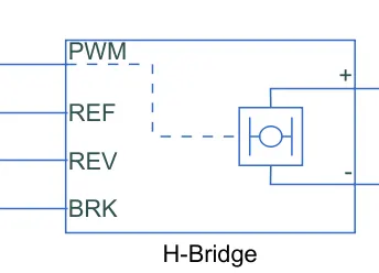
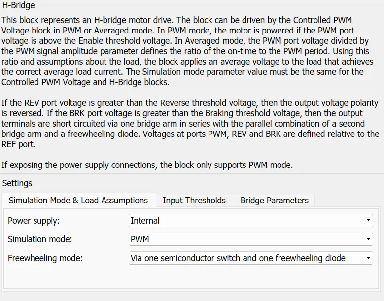
REV: voltage that controls when to reverse the polarity of the H-Bridge block output.
BRK: voltage that controls when to short circuit the H-Bridge block output.
Power supply : Power supply can run in two model Internal and External Mode.
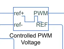
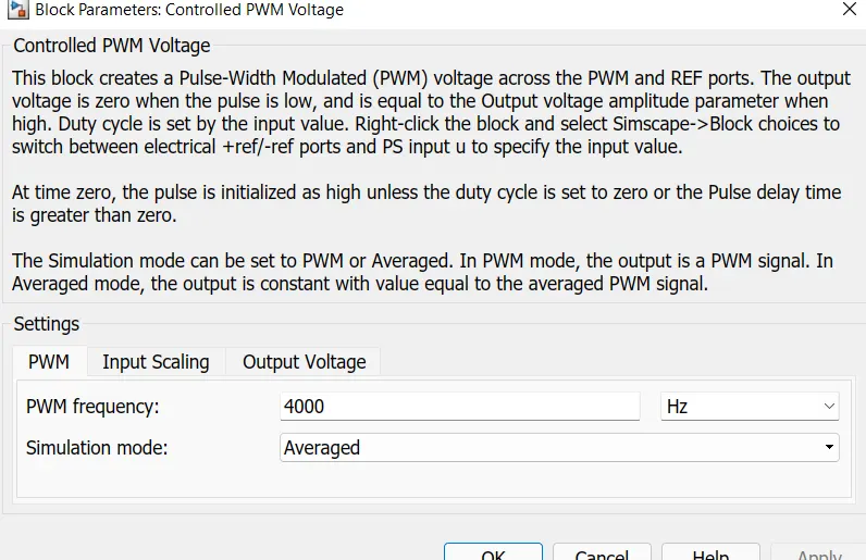
7.Controlled PWM voltage: The Controlled PWM Voltage block represents a pulse-width modulated (PWM) voltage source.
Simulation Mode is AVERAGED to reduce simulation time.
Output voltage: set to 330v (consider as Motor rated voltage)
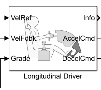
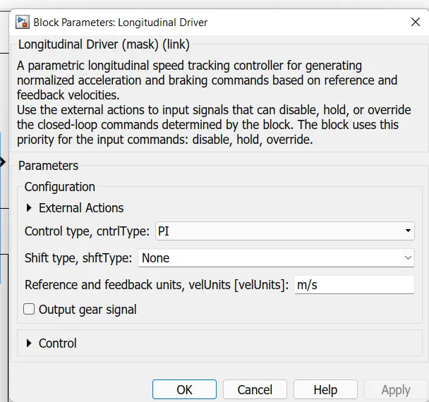
- Lonitudinal Driver:(Acts as Driver of vehicle)The block generates normalized acceleration and braking commands that can vary from 0 through 1.
It is Speed Tracking Block which uses a PI controller to reduce the error between Reference velocity and output velocity and gives Accleration and brake commands to Motor through H-bridge.
All Parameters are set as default.
Grade is set as zero so, there is no gradeability in Vehicle.
9.Drive Cycle:The Drive Cycle Source block generates a standard or user-specified longitudinal drive cycle. The block output is the specified vehicle longitudinal speed
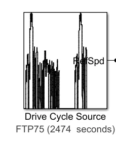
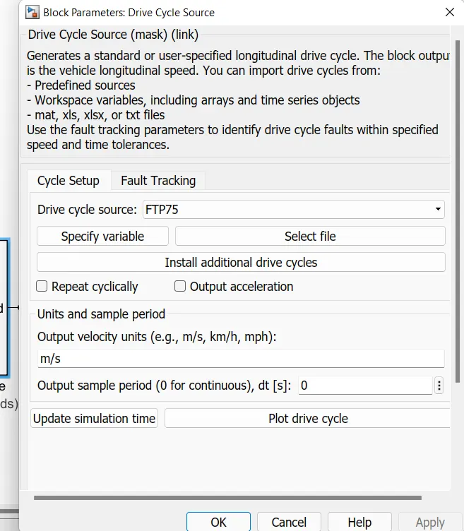
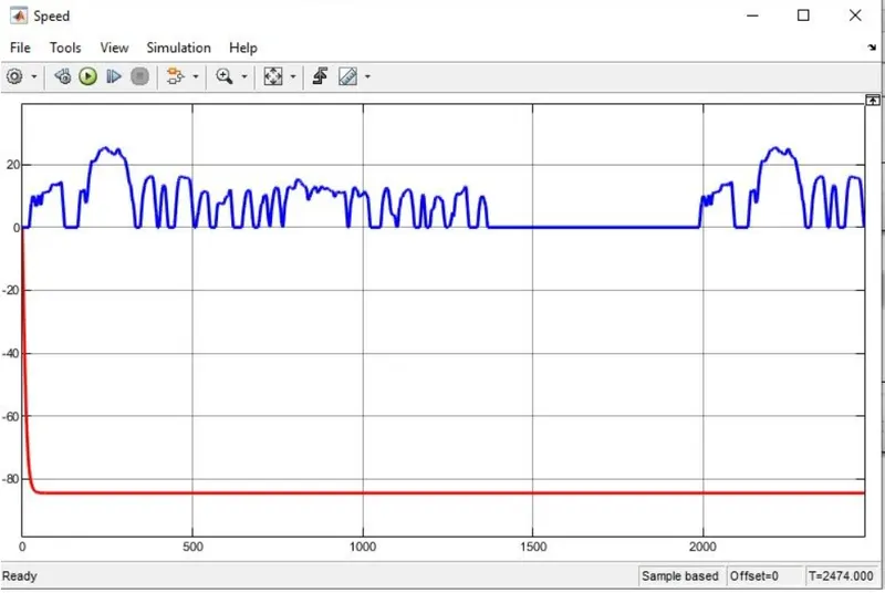
FTP75: used to generate velocity across vehicle and evaluate the vehicle performance.
10.Battery: This block represents the Physical model of battery.

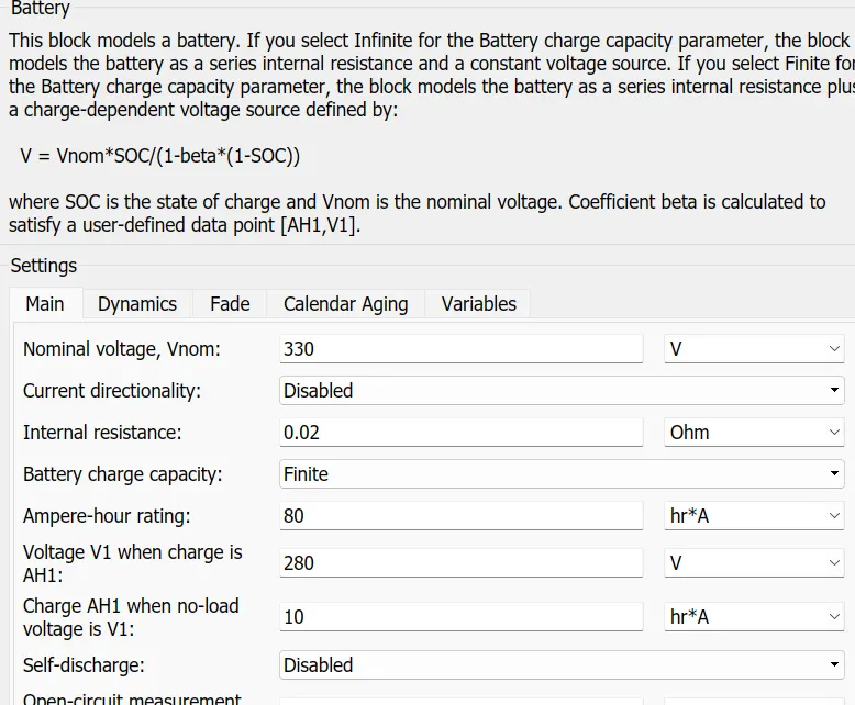
- Battery voltage=Motor rated voltage =330v
- Amphere-Hr rating =80AH
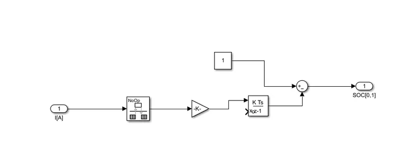
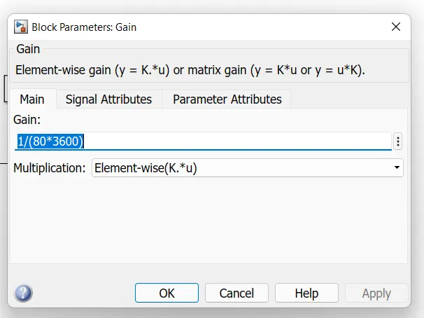
Simulink model of SOC: Current is Integrated and Divide with battery Ampere hour rating (Gain Block)in seconds then subtracted the obtain result from battery full capacity.
Modelling of an EV
- First of all driving cycle used as an input for a driver.
- A longtudinal driver acts as a PI Controller where the vehicle actual speed and refernace speed are measured
- To run the DC motor, converter H bridge is used
- According to the motor AC-AC DC-AC, DC-DC, AC-DC converteris uded to run the motor
- The converter consist of switches and to turn on/off PWM(pulse width modulation) technique is used to control the signal and converter
- The batery is used to measure the current from the vehicle
- Measurement of the speed is constrained by the vehicle body and the tires which are allocated in the subsystem
- Another subsystem contains the data to represents the state of charge of a vehicle in a particular time and driving cycle
OUTPUT WAVEFORMS
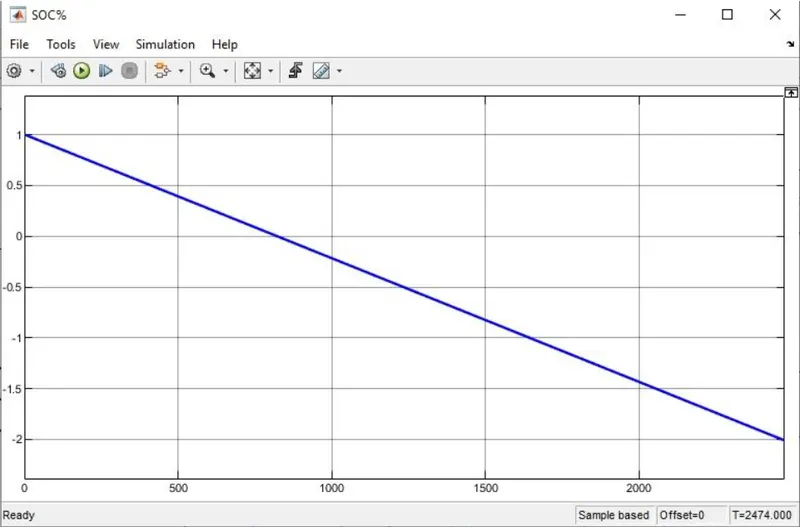
SOC%
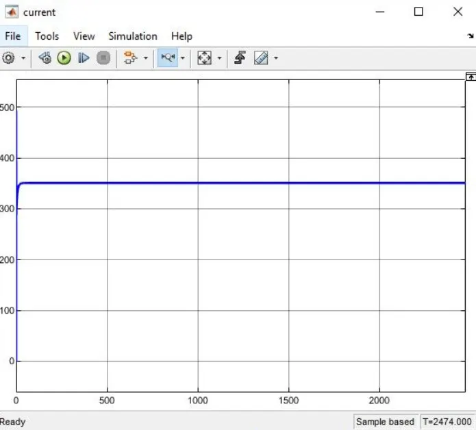
CURRENT
SPEED
Link of simulink model
https://drive.google.com/file/d/1HUhKjypgJOyMUOus7Zh5-USOGWNVuIIr/view?usp=sharing