Final Project: Design of an Electric Vehicle
Aim:
Create a MATLAB model of an electric car that uses a battery and a DC motor. Choose suitable blocks from the Powertrain block set.
Objectives:
1. System level configurations
2. Model parameters
3. Results
4. Conclusion
Introduction:
An electric vehicle is a vehicle that utilizes one or more electric motors or traction motors for propulsion by using the energy stored in energy storage devices or batteries. The advancement of energy storage technology, particularly battery technology makes electric vehicles become more popular these days.
Types of electric vehicles:
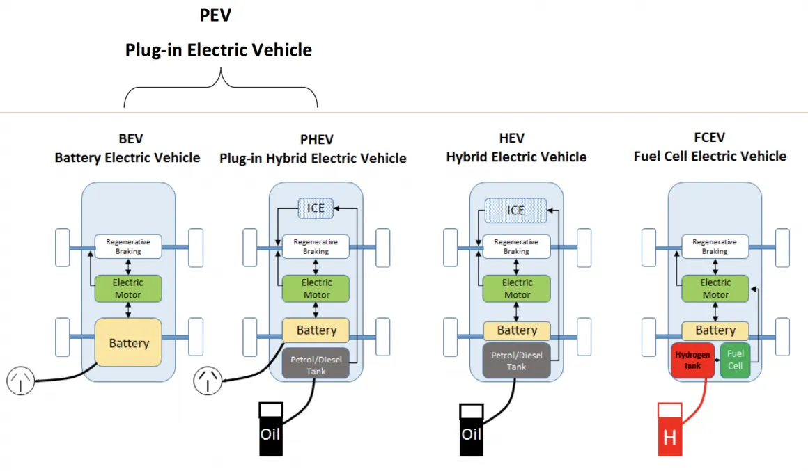
Based on the working principle electric vehicles can be classified into 4 types.
- Battery Electric Vehicle (BEV)
- Plug-in Hybrid Electric Vehicle (PHEV)
- Hybrid Electric Vehicle (HEV)
- Fuel Cell Electric Vehicle (FCEV)
This project is based on the battery-electric vehicle. So working of an electric vehicle is explained below.
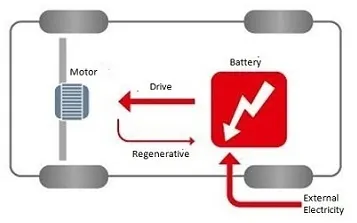
The battery-electric vehicle(BEV) also known as an all-electric vehicle(AEV), runs entirely on a battery and electric drive train. The general working principle of BEV is, that the controller takes and controls the flow of electrical energy from the batteries & inverters. With the controller set, as per the pressure applied on the pedal, the inverter then sends a specific amount of energy to the electric motor. The electric motor converts electrical energy into rotational mechanical energy. The motor rotor rotation rotates the transmission, which thus turns the wheels.
Battery: The battery of an electric vehicle can be charged from the grid power. But aside from the traditional lithium-ion batteries, there are also other significant batteries that can be utilized in electric vehicles. Lithium-ion batteries provide extra performance and range. These are expensive. Nickel metal hybrid batteries provide higher output & better performance.
Motor controller: The motor controller of an electric car administers its complete operation and distribution of power at any given moment. It acts as a switch between the motor and batteries. It has a microprocessor that can restrict or redirect current. It is used to improve the mechanical performance & efficiency of the vehicle.
Electric motor: Unlike the IC engine which has lots of moving parts, a motor has one moving part. Choosing the electric motor relies upon the tractive power requirement. They are constructed to use either AC or DC power. AC motors are more affordable, have less mechanical wear & tear, and are lighter compared to DC motors. However, controlling AC motors is more complex.
Simulink model:
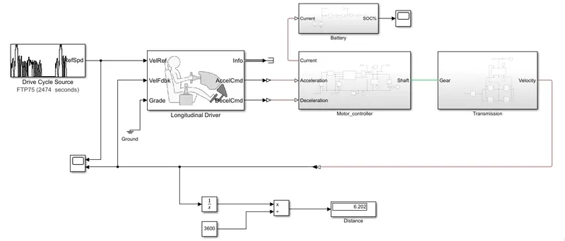
The Simulink model for the electric vehicle is shown below.
Drive cycle source:
The Drive cycle gives the relation between the vehicle speed and the time Generates a standard or user-specified longitudinal drive cycle. The block output is the vehicle's longitudinal speed. The output of this block is the longitudinal speed. This output can be used to:
- Foresee the engine torque, & fuel utilization that a vehicle requires to accomplish the desired speed & acceleration for a given gear shift reference.
- Generate realistic velocity & shift reference for closed-loop acceleration & deceleration commands for vehicle control.
- Study, tune & improve vehicle control, system performance & system robustness over different drive cycles.
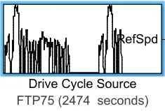
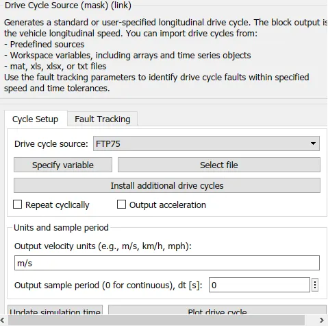
The FTP75 drive cycle is selected in this model as a reference.
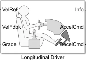
Longitudinal Driver:
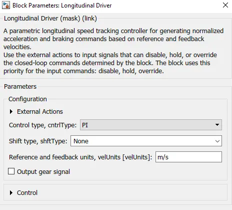
The longitudinal driver carries out a longitudinal speed tracking controller. Based on the reference & feedback velocities, the block produces the standardized acceleration and braking commands. This block can be utilized to model the dynamic response of a driver or to produce the commands important to track a longitudinal drive cycle.
Motor controller:
The motor controller the subsystem block that includes the following blocks as shown below.
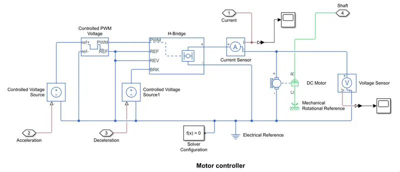
Controlled voltage source:
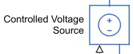
This block addresses an ideal voltage source that is powerful enough to keep up the predefined voltage at its output regardless of the current passing through it. The output voltage is V = Vs, where Vs is the numerical value presented at the physical signal port. The acceleration and deceleration commands from the longitudinal driver block to this block.
Controlled PWM voltage:
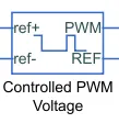
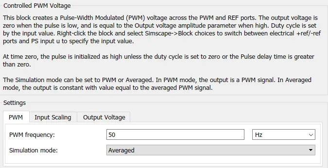
This block creates a Pulse-Width Modulated (PWM) voltage across the PWM and REF ports. The output voltage is zero when the pulse is low and is equivalent to the Output voltage amplitude parameter when high. The duty cycle is set by the input value. This block computes the duty cycle based on the reference voltages across ref+ & ref- ports.
H-bridge:
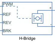
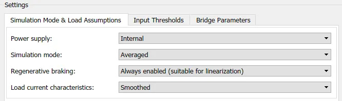
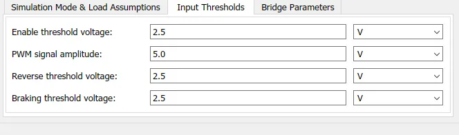
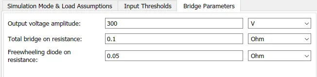
This block represents an H-bridge motor drive. The block can be driven by the Controlled PWM Voltage block in PWM or Averaged mode. In PWM mode, the motor is powered if the PWM port voltage is above the Enable threshold voltage. In Averaged mode, the PWM port voltage divided by the PWM signal amplitude parameter defines the ratio of the on-time to the PWM period. Using this ratio and assumptions about the load, the block applies an average voltage to the load that achieves the correct average load current. The Simulation mode parameter value must be the same for the Controlled PWM Voltage and H-Bridge blocks.
Current & Voltage sensors:

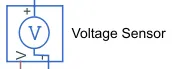
These blocks represent the ideal current & voltage sensors that measure the current and voltage through & across the electrical branch respectively.
DC motor:
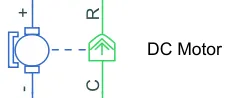
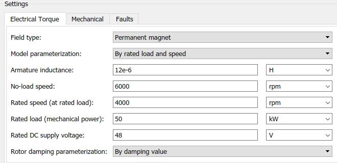
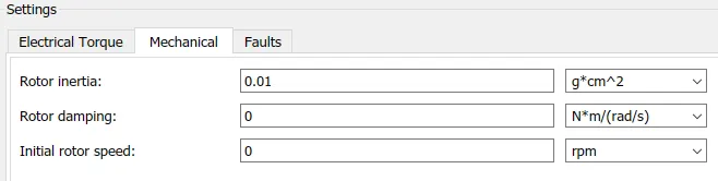
This block represents the electrical & torque characteristics of a DC motor. DC motor converts the electrical energy into rotational mechanical energy. The parameters considered are as shown below.
Transmission subsystem:
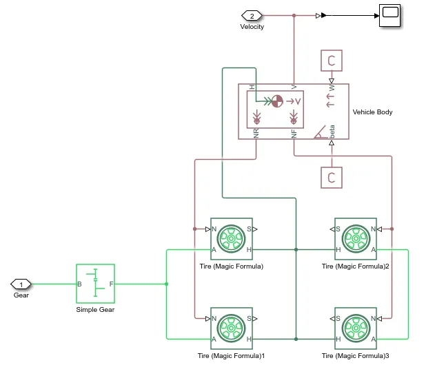
This subsystem consists of the following shown blocks.
Simple gear:

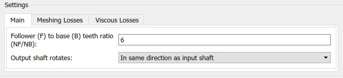
This block is used to represent the gearbox or fixed gear ratio. The base gear is connected to the motor & follower gear is connected to the wheels. If both shafts rotate in the same direction then the speed will be positive otherwise speed will be negative.
Tire:
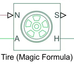
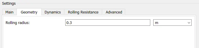
This block addresses the longitudinal behavior of a highway tire characterized by the tire Magic Formula. The block is built from Tire-Road Interaction (Magic Formula) and Simscape Foundation Library Wheel and Axle blocks. Optionally, the effects of tire inertia, stiffness, and damping can be incorporated. The wheel radius is considered 0.3m. The rolling resistance is not included.
Vehicle body:
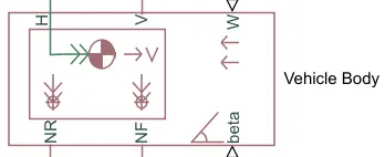
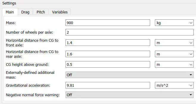
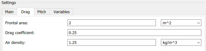
Represents a two-axle vehicle body in longitudinal motion. This block is used to represent the vehicle's body mass, aerodynamic drag, road incline, and weight distribution between axles due to acceleration and road profile. The vehicle can have the same or a different number of wheels on each axle. Optionally include pitch and suspension dynamics or additional variable mass and inertia. The vehicle does not move vertically relative to the ground. The parameters are considered as shown in the figure.
Battery subsystem:
This subsystem includes the following blocks init.
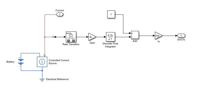
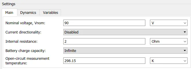
This block is developed to estimate the state of charge of the battery. Based on the motor requirement the current-controlled source discharges the power from the battery. To calculate the SOC nominal battery capacity is calculated in the first gain block. Then calculated the battery SOC throughout the drive cycle. The nominal voltage of the battery is considered 90v.
Result:
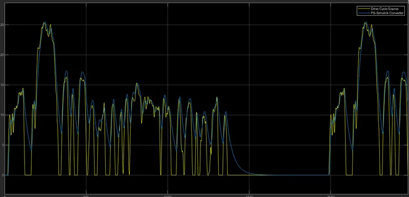
From the above graph, it can be observed that the velocity graph is following the drive cycle graph. So the velocity is dependent on the drive cycle input.
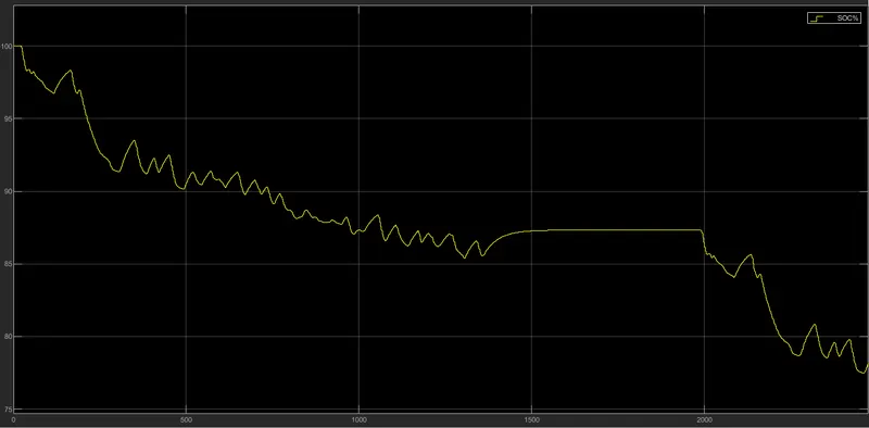
The above graph describes the battery state of charge throughout the drive cycle. Observed that SOC decreases with an increase in time. The speed spikes indicate the regenerative braking.
Conclusion:
The Electric vehicle Simulink model using the battery and DC motor is modeled and simulated successfully for an FTP75 drive cycle source. And the EV drive cycle & the battery SOC results are calculated.