Final Project: Design of an Electric Vehicle
Project: MATLAB model of electric car which uses a battery and a DC motor:
Objectives:
- System level configuration
- Model parameter
- Results
- Conclusion
Solution:
- An electric car is an automobile that is propelled by one or more electric motors, using only energy stored in batteries.
- Block diagram of Electric Car:
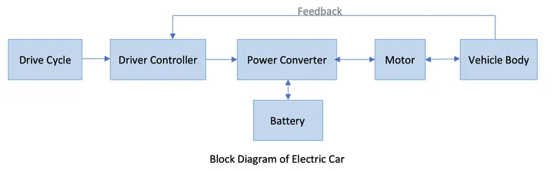
- Vehicle Body:Vehicle body includes a steel frame, wheels, tyres, brakes,transmission system, front and rear axle, etc.
- Electric Motor:Electric motor that converts the mechanical energy into electrical energy and can be powered by AC or DC sources. Here we are using Permanent Magnet DC motor.
- Power converter: Power converter has been designed to carry bidirectional power flow. It can also be used to regenerate the power coming from wheels during braking. Here we are using Motor controller (H-bridge) with regenerative braking.
- Driver Controller: Driver controller track the actual speed of the vehicle and matches it to given input(Drive Cycle).
- Battery: Battery is used to power the electric motor. Usually these batteries are rechargeable.These batteries are specifically designed for a high ampere-hour (or kilowatt-hour) capacity.
- Drive cycle: Drive cycle is variation in speed w.r.t time. It is one of the way to test the range.
Simulink model:
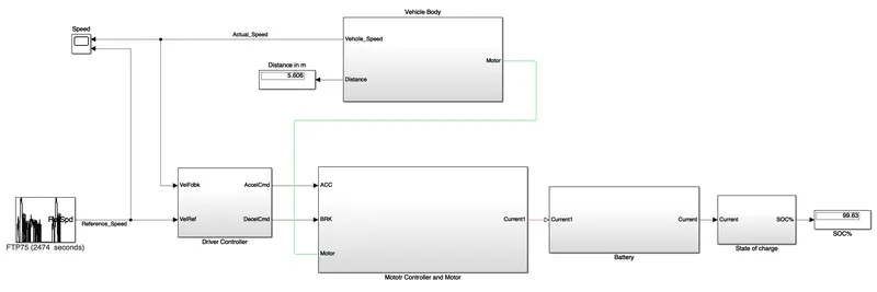
Here, Sub-Systems are:
- Driver Controller
- Motor controller and Motor
- Battery
- Sate of Charge
- Vehicle Body
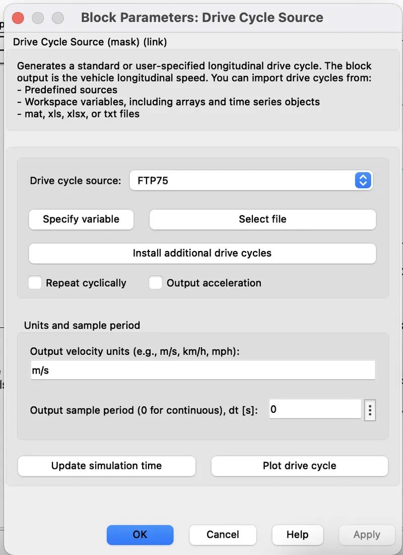
Drive Cycle(FTP75) is used as speed reference:
This is standard velocity(m/s) vs time(s) graph to determine distance/range, Battery performance and many more parameters.
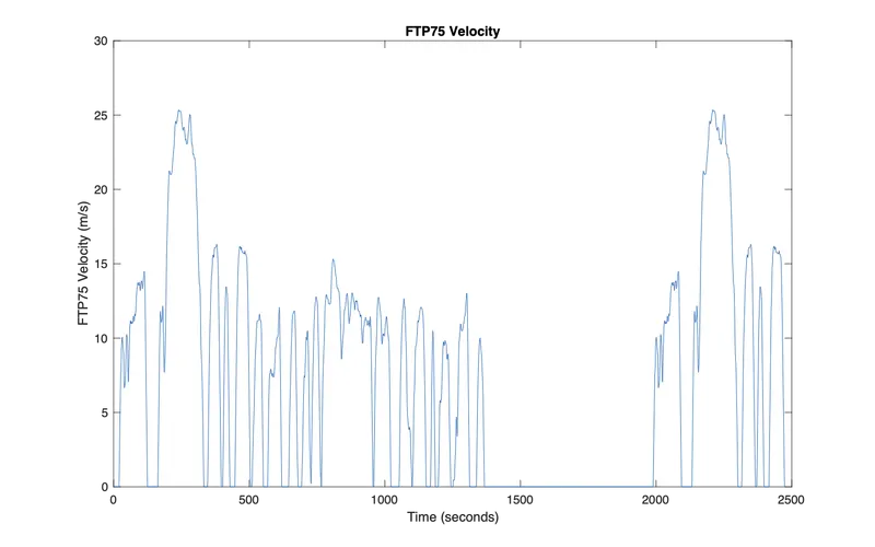
This drive cycle output is given to driver controller subsytem's VelRef Input which is shown below:

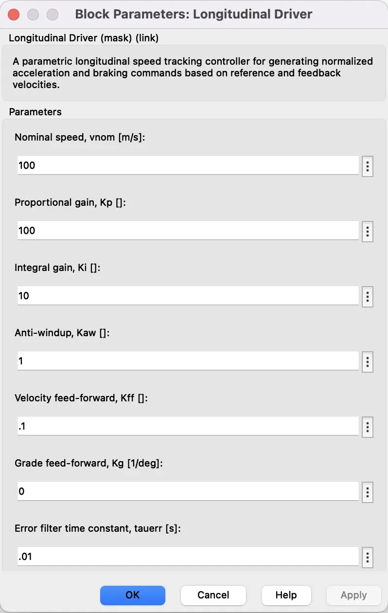
Longitudinal Driver:
- The Longitudinal Driver block implements a longitudinal speed-tracking controller. Based on reference and feedback velocities, the block generates normalized acceleration and braking commands that can vary from 0 through 1.
- The Longitudinal Driver block implements a Proportional-Integral (PI) controller with tracking anti-windup and feed-forward gains.
- VelRef:Reference velocity, vref, in m/s.
- VelFbbk:Forward vehicle velocity, in m/s.
- Grade:Road grade angle, θ, in deg.
- AccelCmd:Commanded vehicle acceleration, yacc, normalized from 0 through 1.
- DecelCmd:Commanded vehicle deceleration, ydec, normalized from 0 through 1.
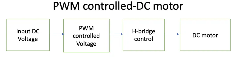
The outputs from AccelCmd and DecelCmd is given to Motor controller and Motor subsytem:
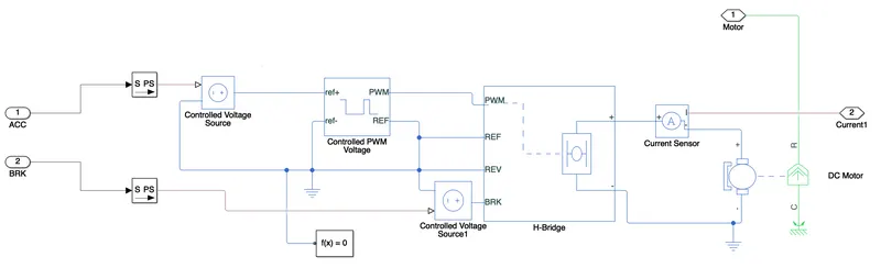
- AccelCmd or ACC is given to Ref+ of Controlled PWM voltage through Controlled Voltage Source.
- DecelCmd or BRK is given to BRK of H-bridge through Controlled Voltage Source.
- PWM of Controlled PWM voltage is connected to PWM of H-bridge.
- Output of H bridge is connected to DC motor through current sensor.
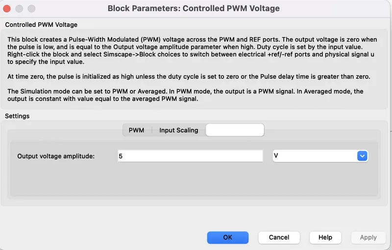
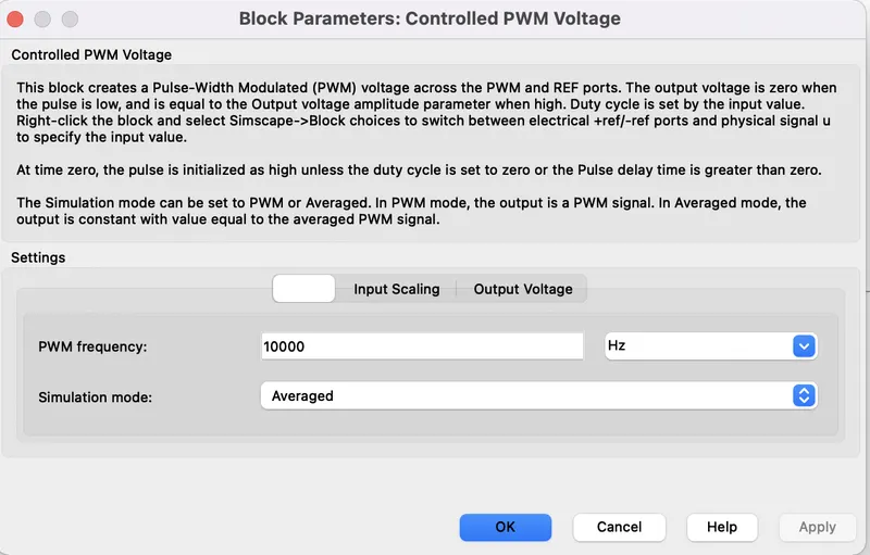
- Controlled PWM voltage: It is set to averaged mode as shown below with input and output=5V.
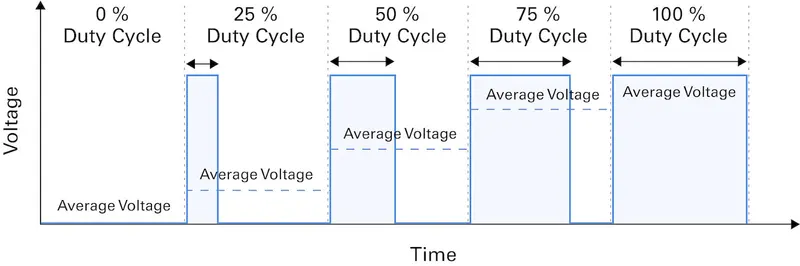
- Averaging Effect:
-
Duty Cycle= (Ton/T)*100% ; where T= Ton + Toff
- H-Bridge: Provide the ability to reverse current across a DC motor, allowing for rotation in either direction. Additionally, H-Bridges allow loads to be powered independently from the control signals that are controlling them, providing circuit isolation.
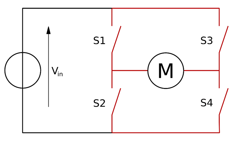
- When the switches S1 and S4 are closed (and S2 and S3 are open) a positive voltage is applied across the motor.
- By opening S1 and S4 switches and closing S2 and S3 switches, this voltage is reversed, allowing reverse operation of the motor.
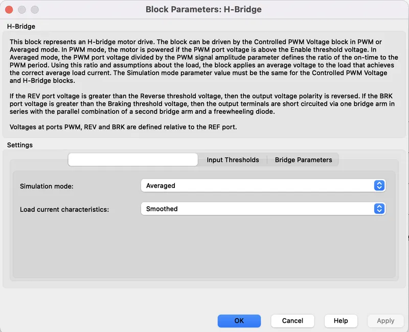
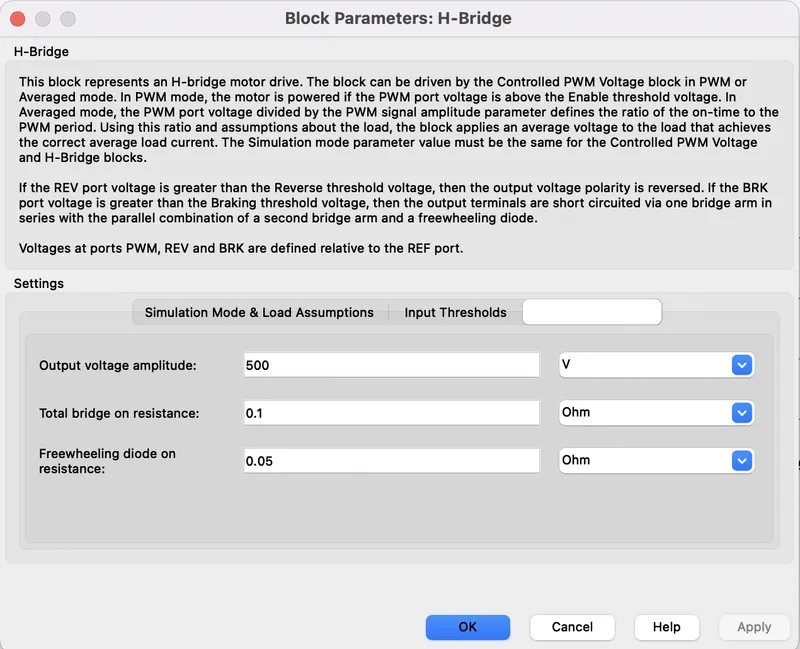
- H-bridge is also in averaged mode, with output=500V.
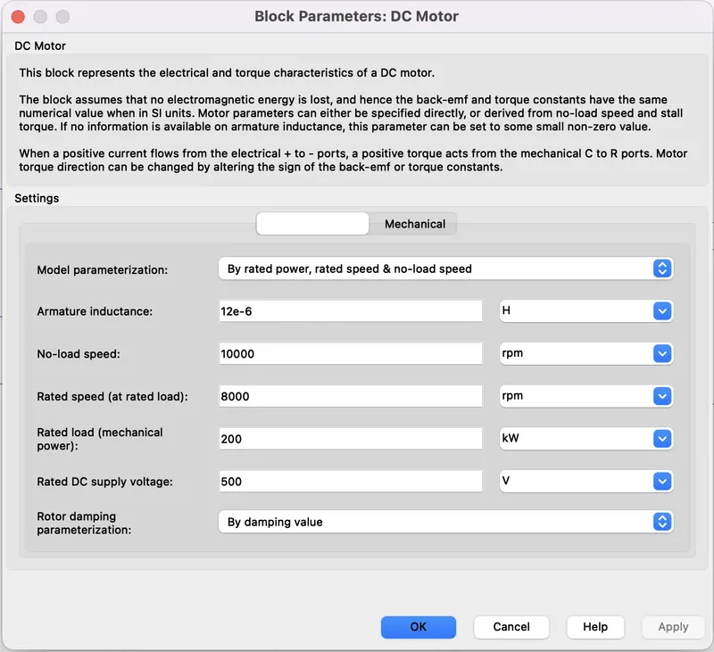
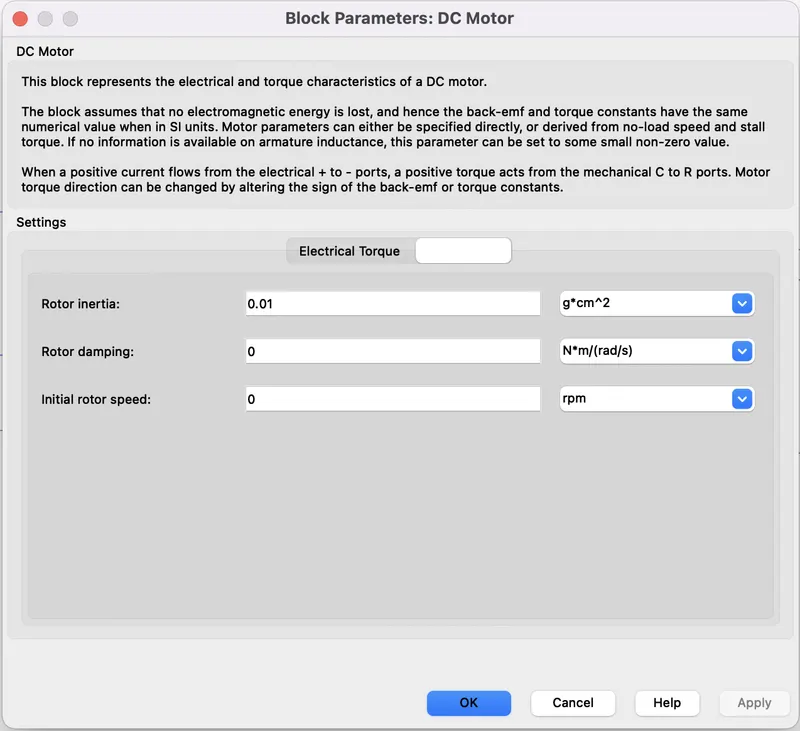
- DC Motor:The DC Motor block represents the electrical and torque characteristics of a DC motor using the following equivalent circuit model:
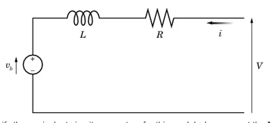
- The resistor R corresponds to the resistance you specify in the Armature resistance parameter. The inductor L corresponds to the inductance you specify in the Armature inductance parameter.
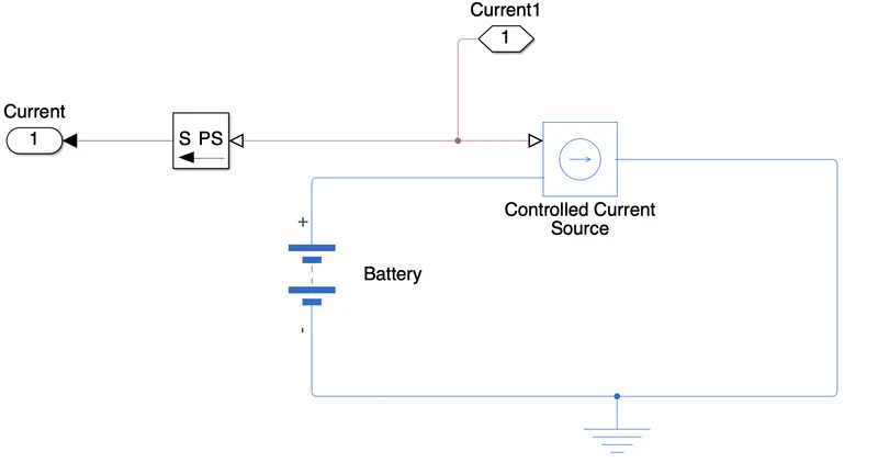
- The current from current sensor is given to battery through Controlled current source as shown below:
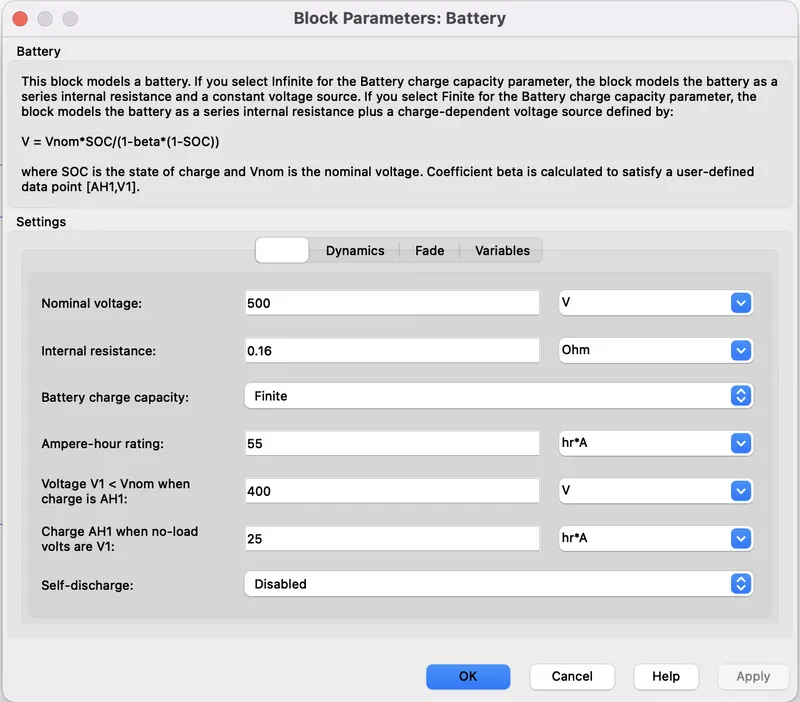
- Battery parameters with nominal voltage of 500V and with capacity of 55Ah.
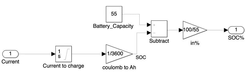
- SOC(State of Charge): Level of charge of an electric battery relative to its capacity. The units of SoC are percentage points (0% = empty; 100% = full).
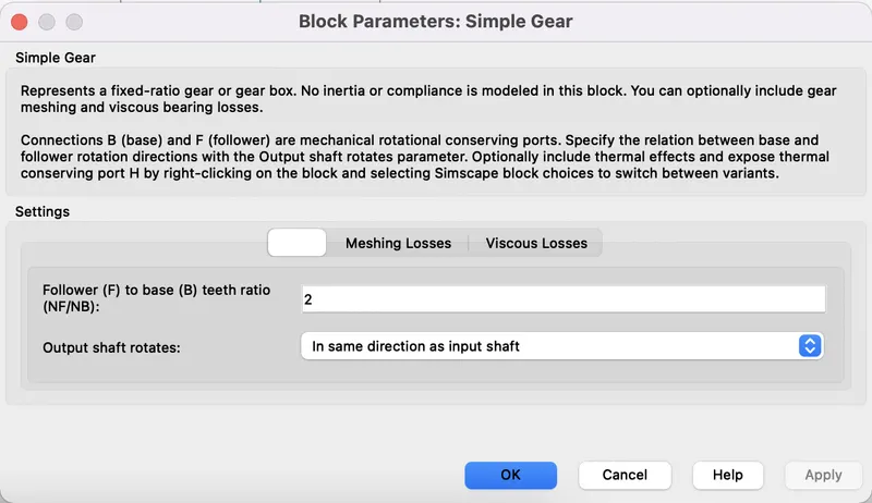
- Vehicle Body Subsytem: This Subsytem consist of Gear box with wheels and vehicle body.
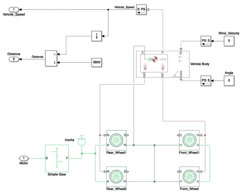
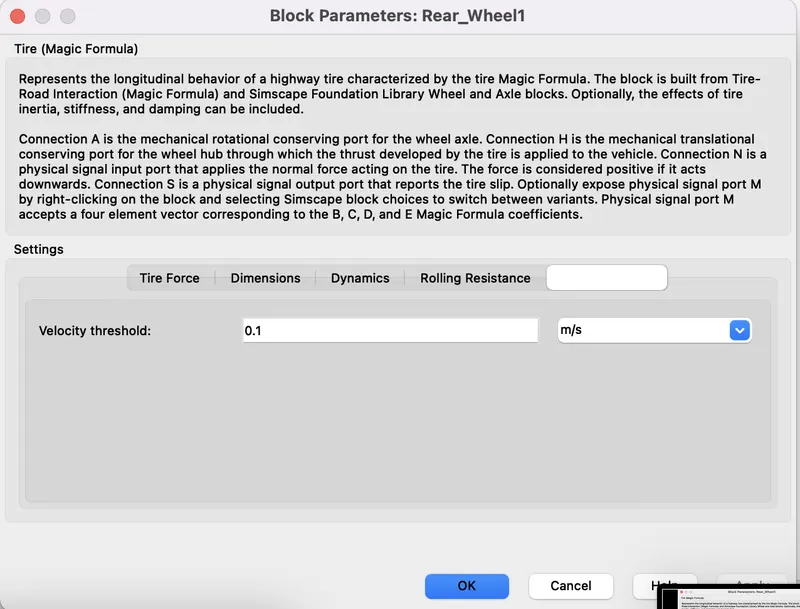
- Wheels or Tires : This car consist of 4 wheels- Two are rear wheels and two are front. On the Rear side, Gear box is used.
- Magic Tire parameters:
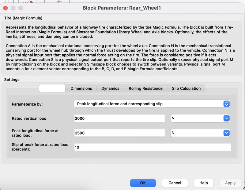
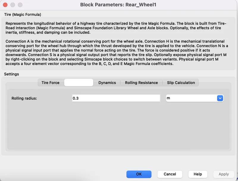
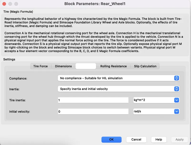
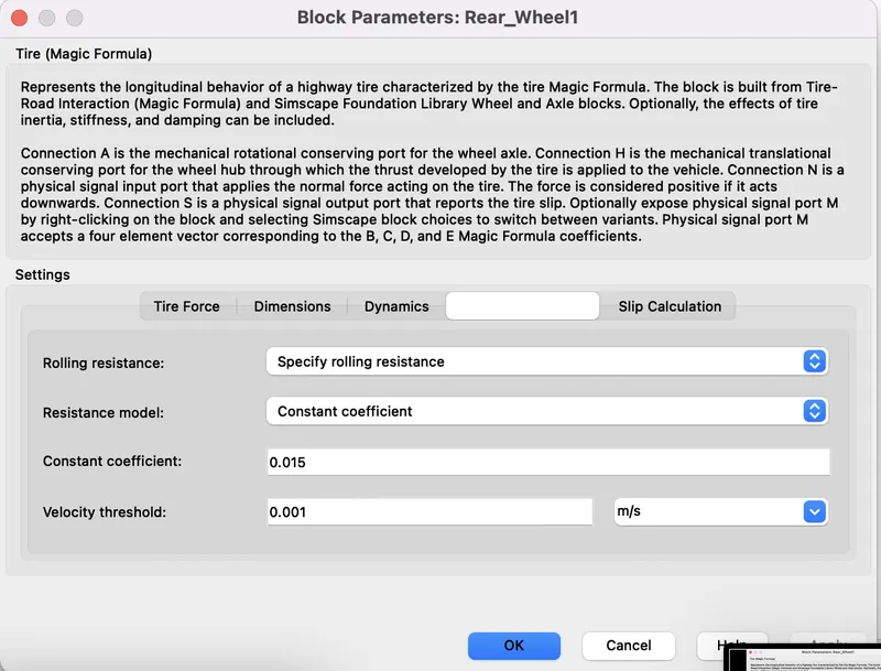
- Simple-Gear parameters:
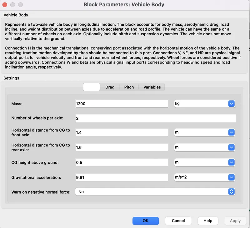
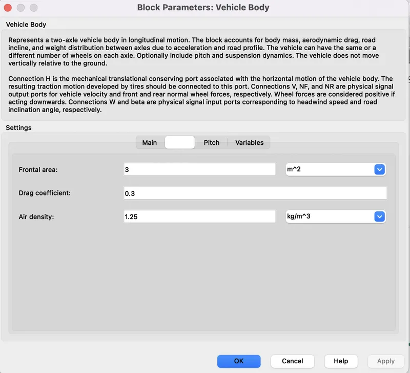
- Vehicle Body:The block accounts for body mass, aerodynamic drag, road incline, and weight distribution between axles due to acceleration and road profile.
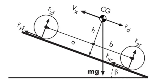
- The vehicle axles are parallel and form a plane. The longitudinal, x, direction lies in this plane and perpendicular to the axles. If the vehicleis traveling on an incline slope, β, the normal, z, direction is not parallel to gravity but is always perpendicular to the axle-longitudinal plane.
- This figure and table define the vehicle motion model variables.
- Inputs:
w-Physical signal input port for headwind speed.
Beta-Physical signal input port for road incline angle.
- Outputs:
V-Physical signal output port for vehicle longitudinal velocity.
NF-Physical signal output port for normal force on the front axle. Wheel forces are considered positive if acting downwards.
NR-Physical signal output port for normal force on the rear axle. Wheel forces are considered positive if acting downwards.
- Output V-Vehicle velocity is goes back to driver controller as feedback and it is converted into distance using integrator.
Results:
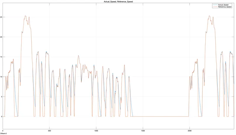
- This graph represents the Actual speed i.e. Vehicle velocity from Vehicle body and Reference Velocity.
- Actual speed follows the Reference speed.
- During Deaccleration, there is large difference between actual and Reference speeds.
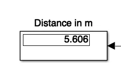
- Distance Covered by vehicle in 2474 secs is 5.606m.
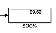
- SOC (state of charge) of battery is 99.63%. i.e. 0.37% battery is discharged in 2474 secs.
Conclusions:
- By controlling the PI gain and incresasing the Voltage levels and by taking the vehicle dynamics in account, performance of the vehicle can be improved.