Final Project: Design of an Electric Vehicle
Aim: Create a MATLAB model of electric car which uses a battery and a DC motor. Choose suitable blocks from Powertrain block set. Prepare a report about your model including following:
1. System level configurations
2. Model parameters
3. Results
4. Conclusion
Introduction: An electric vehicle (EV) is one that operates on an electric motor, instead of an internal-combustion engine that generates power by burning a mix of fuel and gases. Therefore, such as vehicle is seen as a possible replacement for current-generation automobile, in order to address the issue of rising pollution, global warming, depleting natural resources, etc. Though the concept of electric vehicles has been around for a long time, it has drawn a considerable amount of interest in the past decade amid a rising carbon footprint and other environmental impacts of fuel-based vehicles.
It is seen that government is also promoting EV and by 2030 the electric vehicle will boob the market. Many automakers are working on thier vehicles so that they can reduce the pollution and move to electric vehicle for up coming compitation. The researchers and automaker are contineously working on reducing CO2 emission which will be helpfull for envirnoment and our future generation.
Now the engineer are working to find high capacity lithium type battery which has made to amke pure Electric Vehicle possible.
At present with new technologies some manufactures have lanched their products in market such as Tesla, Nissan Leaf which are some example of pure Electric Vehicle.
Some important component of Electric Vehicle:
1. Auxilary Battery: In Electric vehicle auxilary battery is used to power vehicle accessories.
2. Traction Battery Pack: Traction battery pack is also called as Electric vehicle battery which is used to store electricity. below are some example of traction battery pack:
A. Lithium Ion Battery
B. Nickel Metal Hydride
C. Lead Acid
D. Ultra capacitors
The most commoly used traction battery pack is the lithium ion battery which has a good life and good performance.
3. DC/DC converter: DC/DC converter is used to convert high voltage DC power to low voltage DC. The converted power is used to feed vehicle accessories and also to charge auxilary battery.
4. Electric traction motor: This is the part which gives motion to the vehicle. It convert electric energy to mechanical energy.
5. Power Electronic controller: This unit manages the flow of electric energy delivered by the traction battery pack which in turns control the traction motor speed and the produced torque.
6. OnBoard Charger: This takes the incoming AC voltage from the charging port and converts it into DC voltage to charge the traction battery. It moniters battery characteristic such as voltage , current , Temperature and state of charge of the battery during charging.
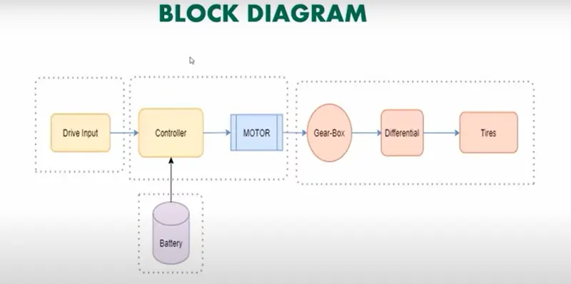
Below shows a block diagram of Electric Vehicle:
MATLAB Modelling of Electric Vehicle:
Mass of vehicle = 1000 Kg
Number of Wheels per axle = 2
By using the MATLAB sumulink we have created model of electric vehicle which is shown below:
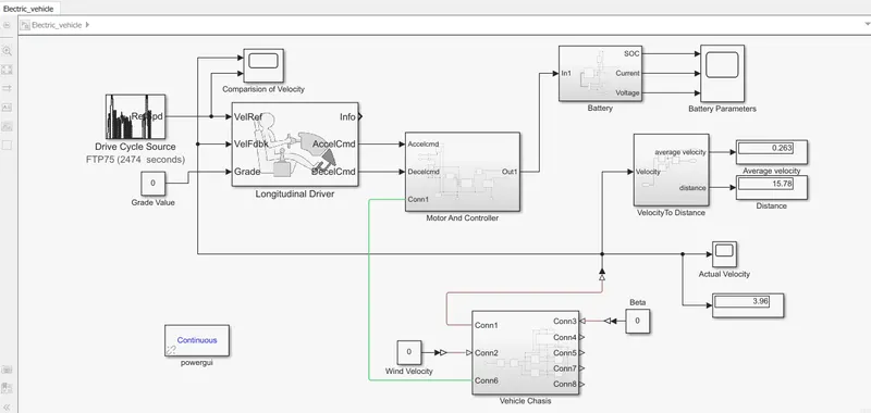
Now we will go into details of each block and their configuration parameter.
1. Vehicle Chassis: I have created a subsystem named vehicle chassis which has those blocks which are related to vehicle chassis such as vehicle block, tyres, differential block and a simple gear.
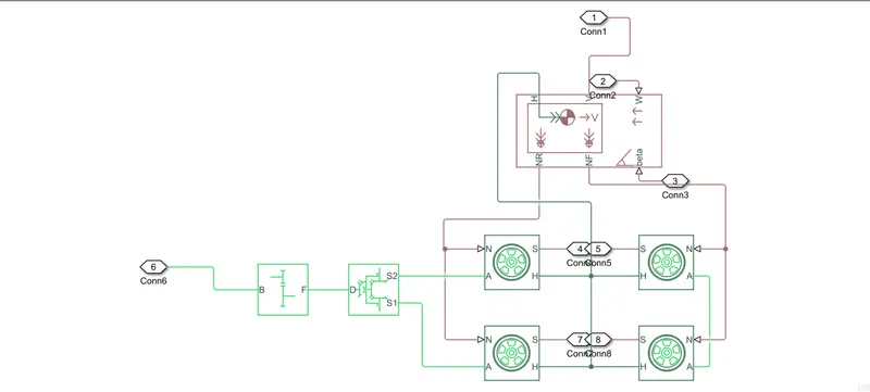
Vehicle Block: The vehicle block represent a two axle vehicle body in logitudnal motion. The vehicle can have same or different numbers of wheels per axle.
The block contain body mass, areodynamic drag, road incline and weight distributed between axle due to acceleration and road profile. Here we can also include pitch and suspension dynamics.
This block has a option of adding externally defined mass and externally defined inertia. The mass, inertia and centre of gravity can be adjusted to manupliate the system outputs.
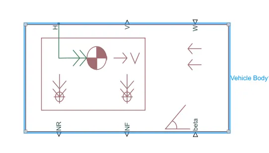
This block has 6 different ports lets see each ports details and their use in this block.
- NR: It is physical wheel output which is connected to rear wheel axle. Here in this model it is connected with normal force of rear tyres.
- NF: It is physical wheel output which is connected to front wheel axle. Here in this model it is connected with normal force of front tyres.
- beta: In this model beta shows the road inclination angle. which we have kept a constant value for simplicity.
- H: This port is horizontal motion of the vehicle body. This port will be connected with all wheels to determine the thrust produced in wheels.
- V: This port is vehicle longitudinal velocity of the vehicle.
- W: This block represents the resisting wind velocity. which we have kept a constant value for simplicity.
Now we know the different ports in Vehicle block and lets see the block parameters. To go into Vehicle block parameter we need to just double click on the block.
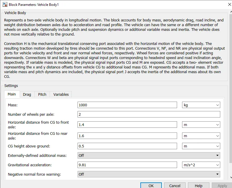
Above shows the block parameter of vehicle block where we have not change much just we have changed vehicle mass to 1000 kg.
Here under setting we have more four subsetting tabs:
Main:
Mass = 1000 Kg
Number of wheel per axle = 2
Horizontal distance from CG to front axle = 1.4m
Horizontal distance from CG to rear axle = 1.6m
CG height above ground = 0.5m
Externally defined added mass = Off
Gravitational Accelration = 9.81m/s^2
Drag:
Frontal rea = 3m^2
Drag Coefficient = 0.4
Air Density = 1.18kg/m^3
Pitch:
Dynamic pitch = Off
Variable:
Beginning values of velocity = 0m/s
Tires block: The tire block models a tire with longitudinal behaviour givenby the magic formula, an imperical equation based on four fitting coefficients. The block can model tires under dynamic loading too. Tis models a tire with a rigid wheel tire combination in contact with the road and subjected to slip.
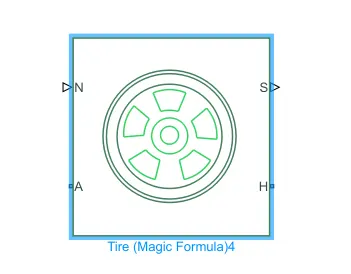
when torque is applied to the wheel axle the tires pushes the ground and transfer the resulting back force on the wheel. This action pushes the wheel forward or backward to give motion to the vehicle.
Tire block has four ports to it lets see details about the ports:
- N: This shows Normal force acting on the wheel and is connected with NR of the vehicle body.
- S: This shows slip between the road and the tire block.
- H: It represent the hub of the wheel and is used to calculate the wheel thrust and is connected to H port of vehicle body.
- A: Axle and rear axle are connected with differential for different speed of both the wheel during turning of vehicle.
Now we know the different ports in Tire block and lets see the block parameters. To go into Tire block parameter we need to just double click on the block.
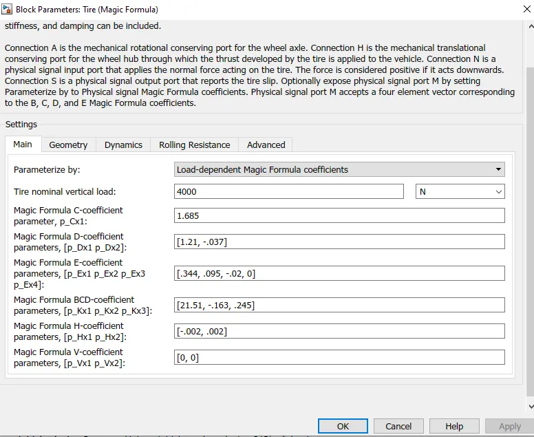
Here under setting we have more five subsetting tabs:
Main:
Parameterize by = Load depended magic formula coefficient.
Tire nominal vertical load = 4000N
And all the magic formula coefficient are same.
Geomerty:
Rolling radius = 0.3m
Dynamic:
Inertia = no inertia(i.e we have not added any seperate inertia block)
Rolling resistance:
Rolling Resistance = On it will basically the rolling resistance in the wheels.
Resistance model = Constant coefficient
Constant coefficient = 0.015
Velocity Threshold = 0.0001m/s
Advanced:
Velocity Threshold = 0.1m/s
Differential block: This is a block Which is used while turning of vehicle because at that moment the outer wheel will rotate at a higher speed than the inner one this speed diference is done by using differential block.
Below a differential block is shown:
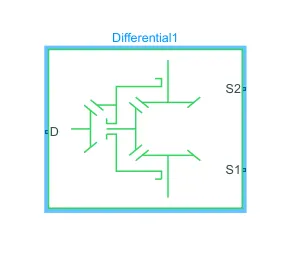
To go in parameter again we just need to double click on the block and here in this block we have not changed any parameters.
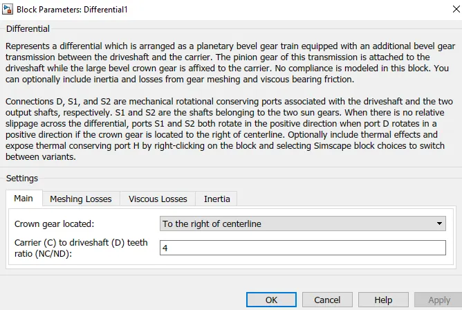
Here also we have four subsetting tab but we have not changed any of those values.
Simple Gear: Simple gear is a final drive ratio which is gear box which constrains the connected drive line axes of the base gear and the follower gear.
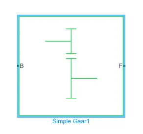
This block has two ports:
- B: The output B, base gear is connected with the input of DC motor R. It is rotational mechanical conserving port.
- F: Follower gear is connected with rear axle. this is also rotational mechanical conserving port.
Now we know the different ports in simple gear block and lets see the block parameters. To go into simple gear block parameter we need to just double click on the block.
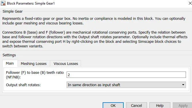
Here we have made some changes.
Main:
Follower to base teeth ratio = 2
Output Shaft rotation = In same direction as input shaft.
Meshing losses:
Here we have selected constant efficiency for friction model under which efficiency is 0.8 and follower power threshold is 0.001W.
2. Motor And Controller: Here we have all electric system and a motor which is when supplied by electric current transforms this electric energy into mechanical rotation. The same motor which is used to rotate the wheels during forward motion will now act as generator during braking action and this electric current produced by the generator will be used to charge the battery.
The blocks used in Motor and controller subsystem are DC motor, H bridge, controlled PWM voltage, Current sensor and control voltage source.
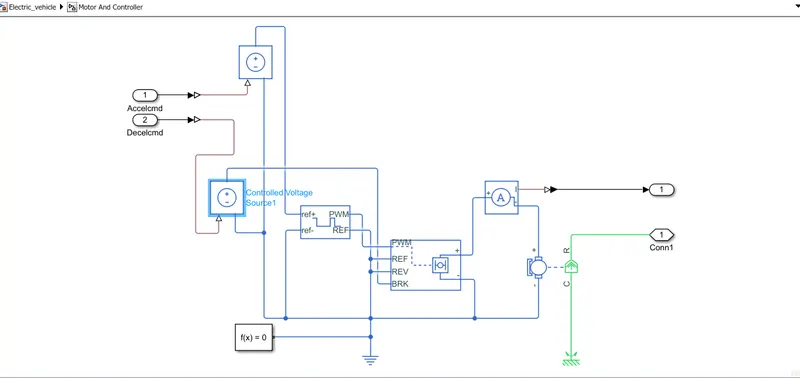
Now we will go into details of each block and their configuration parameter.
1. DC motor: The DC motor block represents the electrical and torque characteristic of a DC motor using the following equivalent circuit mode. Below shows the block of a DC motor:
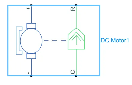
DC block has four ports in it lets see where this ports are connected:
- +: The positive terminal of the motor is connected with the Negative terminal of current sensor block.
- -: The negative terminal of the motor is connected with the electric ground (i.e Earthing)
- R: R in DC motor is a rotor which is connected to mechanical rotating parts.
- C: C in DC motor is connected with mechanical reference.
Now we came to know about different ports in DC motor block. Lets go to block configuration and check the block parameters.
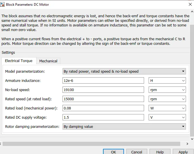
Here we have two subsetting inside the block configuration parameter
1.Electrical Torque:
Model parameerization: By rated power, rated speed and no load speed.
Armature inductance: 12e-6
No load speed: 19100
Rated speed: 15000
Rated load: 0.08
Rated Dc supply voltage: 1.5
2. Mechanical:
Rotor inertia: This is a resisting to the motion of rotor and the value is taken as 0.01
Rotor damping: 0
Initial Rotor speed: 0
2. H bridge: The H bridge block is used to control motor direction such as forward motion and reverse motion of the vehicle.
This is how an H bridge block looks as in simulink:
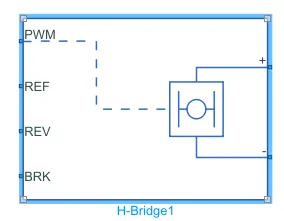
Here in the block we have all total 6 ports. lets see details of each ports and their connection.
- PWM: Pulse-width modulated signal input port.
- REF: Reference, it is an electrical conversing port associated with the floating zero voltage.
- REV: Reverse, It is an electrical conversing port associated with the control in voltage to make vehicle move front and in back direction.
- BRK: Break, It is an electrical conversing port associated with the voltage that control when to short circuit the H bridge block output.
- +: This port is connected to motor through a current sensor block in the middle.
- -: This port is connected to the electrical reference block.
Now we came to know about different ports in H bridge block. Lets go to block configuration and check the block parameters.
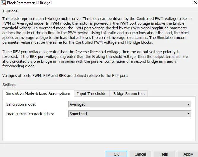
Here under configuration we have three subsettings lets see all of this one by one:
1. Simulation mode and load assumption:
Simulation mode: we have changed that to averaged so that simulation will take less running time.
Load current characteristic: smoothed
2. Input thresholds:
Enabled Threshold voltage = 0.0001
PWM signal amplitude = 1
Reverse threshold voltage = 0.0001
Braking threshold voltage = 0.0001
3. Bridge parameters:
Output voltage amplitude = 50
Total bridge on resistance = 0.1
Freewheeling Diode on Resistance = 0.05
3. Controlled PWM voltage: The controlled PWM voltage represent a pulse width modulated voltage source. Below shows the block :
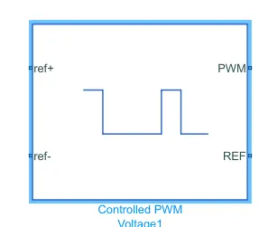
This block has 4 ports in which two of them are reference ports i.e one as input reference and second as output reference.
The port ref+ is connected to the output of controlled voltage source of acceleration command. and the ref- port is connected with the electrical ground(i.e earthing).
Now we came to know about different ports in Controlled PWM voltage block. Lets go to block configuration and check the block parameters.
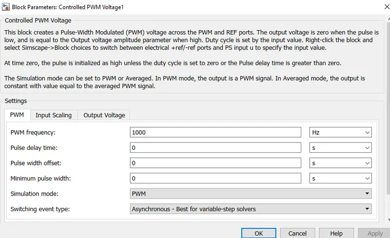
Here under configuration we have three subsettings lets see all of this one by one:
1.PWM:
PWM frequency = 1000
pulse delay time = 0
pulse width offset = 0
minimum pulse width = 0
simulation mode = PWM
2.Input Scaling:
Input voltage for 0% duty cycle = 0
Input voltage for 100% duty cycle = 5
3. Output voltage:
Output voltage ampiltude = 5
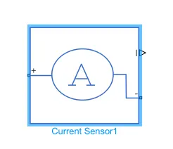
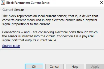
4. Current sensor: This block is a device that converts current measures in an electric branch into a physical signal proportional to current.
Connection + and - is a conserving electrical port through which the sensor is inserted into the circuit. connection I is a physical signal port that outputs current value.
The block is shown below with its configeration parameter tab to:
5. Controlled voltage source:
The block represent ideal voltage source that is powerful enough to maintain specific voltage at its output regardless of current passing through it.
The block is shown below with its configeration parameter tab to:
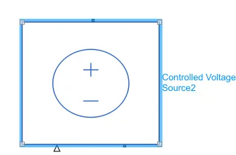
3. Battery: This is a block which gives power to all the electrical system and motor also. The battery of the simulink is of two type we have used a battery for which we get SOC directly in the output. The battery subsystem has a battery and a controlled voltage source.
The battery subsystem is shown below:
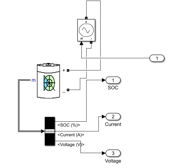
The battery block is shown below:
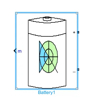
The battery has 3 ports as shown above.
1. +: The positive terminal is connected to the positive terminal of controlled voltage source.
2. -: The negative terminal is connected to the negative terminal of controlled voltage source.
3. m: This m port is used to get the status of the battery conditions.
Lets see the block parameters by double clicking on the battery block:
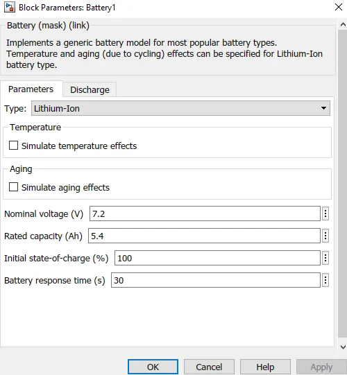
Here We have to only select Lithium-Ion battery which has high performance compared to other batteries.
Controlled voltage source:
The block represent ideal voltage source that is powerful enough to maintain specific voltage at its output regardless of current passing through it.
The block is shown below with its configeration parameter tab to:
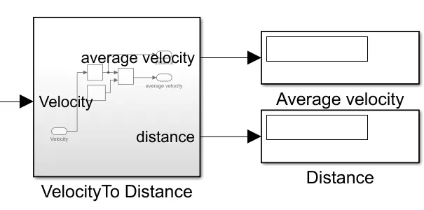
4. Velocity To Distance: This subsystem helps us to get the distance covered by the vehicle after a run of some time.
The input to this subsystem is velocity which is integrated using integrator block to get distance covered and is divided by 3600. which will give the average velocity.
The subsystem is shown below:
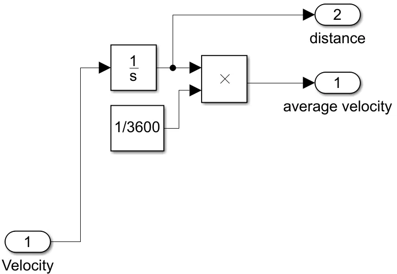
The average velocity output is connected to a display block which will give the tatal distance covered by the vehicle in km/hr.
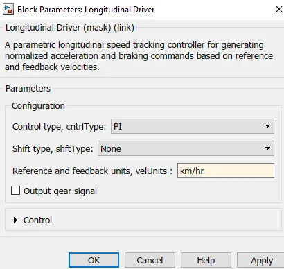
5.Longitudinal Driver: A Longitudinal Driver block impliments a longitudinal speed tracking control.
The longitudinal driver block is shown below:

Here we can see that the block has all 6 ports now lets see what this ports means and where it is connected.
1.VelRef: This is the port where our actual drive cycle are connected.
2.VelFdbk: This is the actual velocity of the vehicle. This will come from vehicle chassis subsystem.
3.Grade: This port takes the input of gradeability of the vehicle which we have kept as constant value.
4.Accelcmd: This port gives acceleration command to the H bridge and according to that the current is supplied to the motor.
5.Decelcmd: This port gives deceleration command to the H bridge and according to that the current is supplied to the motor to decelerate the vehicle.
The block parameter setting of longitudinal bolck is only we have changed the units of velocity from m/s to km/hr.
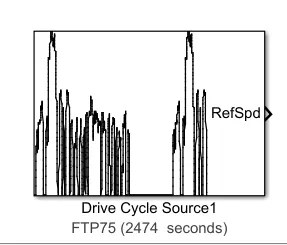
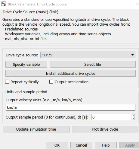
6. Drive cycle source: This will give velocity to the system at different time values.The drive cycle block is shown below.
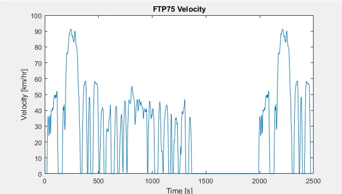
The polt between the veloccity as time is shown below for FTP75 drive cycle with is for 2474 sec.
The block parameters of this drive cycle is shown below from which we can switch to different drive cycles.
Here we have discussed all the main blocks that we have used in our model with model configuration parameters. We have also left some block such as scope, display, etc which are common block.
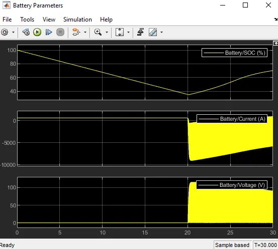
Results: Here we have simulated the model for 30 sec and the outputs of the model is shown below.
1. Battery Parameters: Here the output graph shows SOC, current, voltage consumption of the battery unit.
2. Comparision of drive cycle velocity and the vehicle velocity:
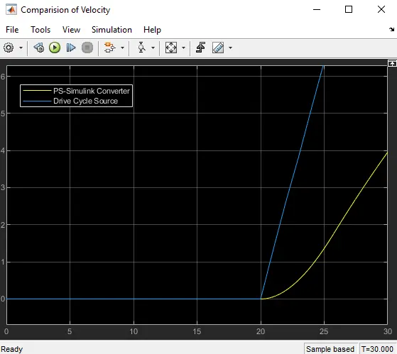
Here in this graph we see two curve the blue one is the drive cycle velocity and the yellow one is the actual vehicle velocity. In the graph we can see that the drive cycle velocity increases rapidly from 20 sec but the avtual vehicle velocity will increase gradually due to the surrounding resistance to the vehicle.
The graph below shows the comparision of both for 30 sec time period.
3. Average speed and total distance covered: This will show the distance travelled by the vehicle for a particular time span. The distance calculated is in meters. To get average speed we need to divide total distance upon total time.
Here is the two display blocks one shows the total distance covered by the vehicle and the next one shows the average speed of the vehicle.
The subsystem with the two dispaly block is shown below:
Conclusion:
The DC motor is used to power the rear axle of the vehicle and when the vehicle is at no load condition the no load speed of the DC motor is set to 19100 rpm and the when the vehicle is at some loaded condition the motor rpm is set to 15000. The supply voltage to the DC motor is 500 V.
The total distance covered by the vehicle for the first 30 sec is 15.78 meters.
Here I have taken my vehicle specification and obtained the above results one can change the model parameters of the vehicle and can get a different results from the same model.