Final Project: Design of an Electric Vehicle
Design of electrical vehicle:
Electrical vehicle:
Electrical vehicle is most popular technology in current era and is developing it’s technology. It has capability to overcome the problem of pollution and it has many more advantages. In this project simulation the design of electrical vehicle is done using simscape and Simulink blocks. The traction motor used for that purpose is permanent magnet DC motor. The battery SOC , output speed of vehicle are observed.
Objective of that project is:
- System level configurations
- Model parameters
- Results
- Conclusion
Description of various Components in the Model:
Tire:
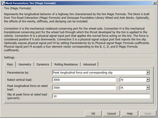
Tire is the main and most important part of the vehicle. Tire is the interaction component between road pavement and vehicle. In MATLAB simulation the tire is works on the magic formula.
The equation used for that is magic formula named because there is no particular physics basis in the equation selection.
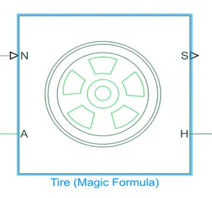
Above is the tire block in the MATLAB. It has four terminal N,A,S,H
- N- This port is called “normal” and it is the force acting normal to the tire and it is considered positive in the downward direction.
- A-Axel of the tire. A is the mechanical rotational conserving port for the wheel axle
- S- “Slip” represent the slip acting on the tire.
- H- Hub of the tire
Vehicle Body:
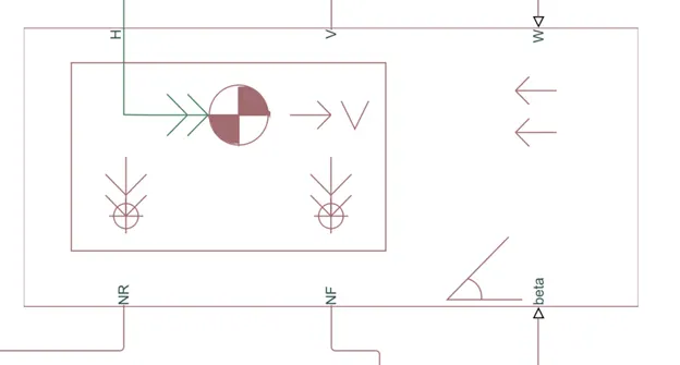
Vehicle body is the upper most part of the vehicle connecting to the tire arrangement segment.
It consists of the driver and passenger seating arrangement.
In MATLAB the vehicle body block is given. It consists of various input and output representing the parameter affecting on the vehicle and according the output port are also given.
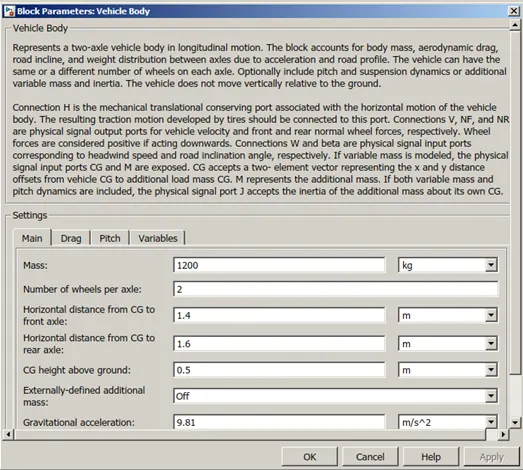
Mass of the vehicle is 1200 kg.
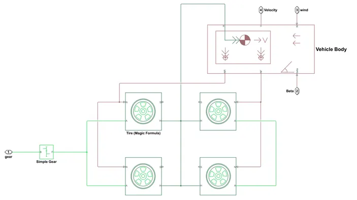
- NF, NR– connecting port tire and the vehicle body. Frontal normal and rear normal forces on the vehicle body respectively
- V- Velocity of the vehicle body or say velocity of vehicle in m/sec
- Beta- Grading angle of the vehicle
- H – Connecting port from the tires and vehicle body. It connects to the hub of the tires of vehicle.
- W – Wind velocity in m/sec. Affects the vehicle performance.
Simple Gear:
It is the gear arrangement which is arranged between the motor vehicle transmission.
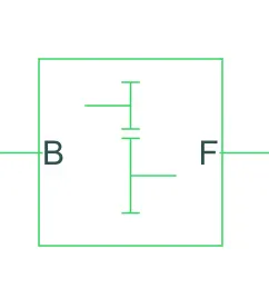
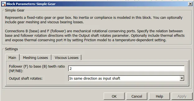
B is stands for number of base gear teeth and F is follower gear teeth.
The Ratio of Nf/Nb = 2 and also the direction of rotation of shaft is same as direction of rotation of input shaft.
DC Motor:
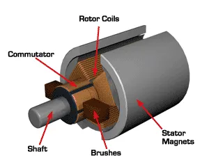
The basic working principle of DC motor is that when a current carrying conductor in the magnetic field it experiences the force.
Traction motors are very important part in the electrical vehicle, which convert the electrical energy into rotation energy and transfers to the vehicle. Here for the regenerative braking the motor must have magnetic field unlike induction motor. The DC motor used here is the permanent magnet type motor.
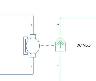
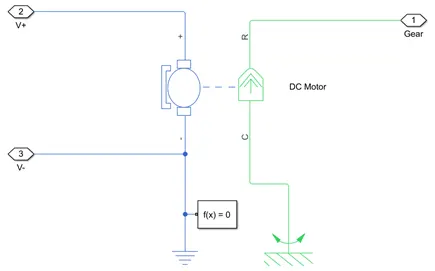
In the next image the DC motor is connected to the CR mechanical rotational port. Which is a just coupling between the electric motor and the mechanical rotational part.
Various parameter has set for the DC motor block that are indicated in the next image.
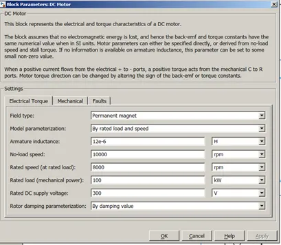
The motor type is DC permanent magnet motor andhence it has self constant field flux. The rated load and rated speed are also specified.
Drive Cycle:
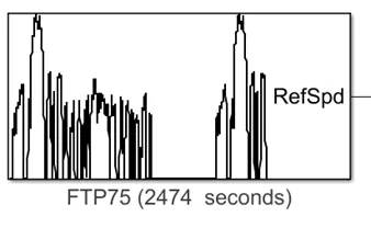
Driving cycle is the driver behavior data for the various road condition. There are many types of the driving cycle for the user and it is recorded for the purpose of the study and to know about the vehicle behavior under those various road condition.
In the simulation the FTP75 driving cycle and the total running time for the driving cycle is 1500 seconds.
In that driving cycle the after 1500 seconds the driving cycle repeats itself.
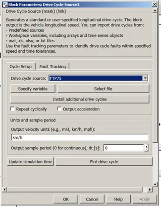
In the above image the FTP75 driving cycle data is in the km/hr. When connected to the longitudinal driver it automatic convert itself from km/hr to m/s.
Longitudinal Driver:
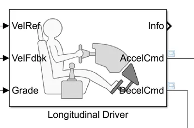
Longitudinal Driver is nothing but PI controller. Basically PI controller is used for the reducing the error between the reference signal and the actual signal. It takes three input which are Velocity reference, Velocity Feedback and grading of the vehicle.
Controlled current source:
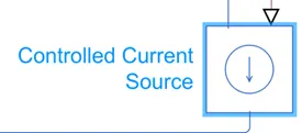
Controlled current source is the current source producing the output current in the given branch as signal provided to that block.
In the simulation the controlled current source is used in the SOC subsystem. The controlled current source is connected to the battery so that it can replicate the current discharging and charging on the external battery, as in H-bridge the voltage source is selected as internal.
Controlled Voltage source:
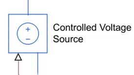
Controlled voltage source is the voltage source producing the output voltage as the signal provided to that block.
In the simulation that block is connected to the Acceleration and Deceleration command output of the longitudinal driver.
Also that output of the controlled voltage source is connected to Controlled PWM voltage to produce the required PWM pulses that can be used as control signal of H-Bridge.
Controlled PWM Voltage:
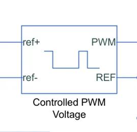
Controlled PWM voltage is the block which produces the PWM for the power electronics converters for control the output parameter of the converter.
In the simulation it is used for the H-bridge which is power electronics converter, used for controlling the output voltage for electric motor.
Various configuration parameters are provided for the controlled PWM voltage.
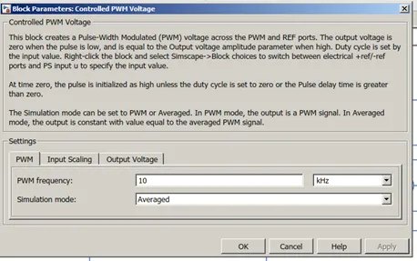
The PWM frequency is selcted as kHz and the simulation mode is average, that means the output will be in average manner not in PWM manner where pulse width is manipulate accordig to reference.
H Bridge:
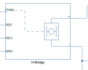
H- bridge is the most important part of the electrical vehicle system as the voltage control is done with that and also the regenerative braking can be implemented using this power electronic converter called H-bridge.
Block contain various input for electrical vehicle application.
PWM is the input for the PWM command that can be provide through controlled PWM converter. The reference is connected to electrical reference as well as reverse also connected to the ground as in the drive cycle there is no reverse direction or not wanted in analysis.
Brake input port is connecting to the brake signal producing block such as controlled voltage source.
Various input configuration are shown here .
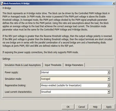
The simulation type is selected as averaged, that means the output current and voltage will be averaged in manner. The other option in that is PWM , that means the output will in pulses manner. Also the regenerative braking is eneabled.
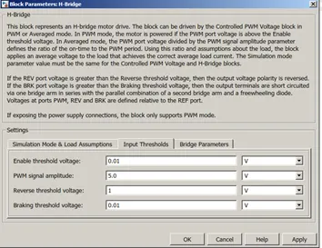
In the above input configuration the thresold voltage are given for enable , breaking and reverse thresold voltage.
Rate transition block:
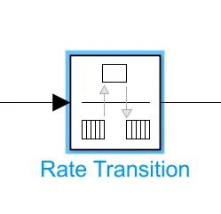
Rate transition block is used to handle the rate of transfer of data. It is act as a unit delay in the given system, and prevent from the error due to the calculation of the state.
Gain:
Gain block is used as multiplier to the input data. It can multiply the data where the block is placed in between.
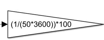
In the simulation it is used in SOC sub system and to convert the speed from m/s to km/hr.
Go to and from block:
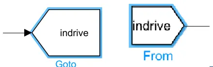
As name suggests the goto and from block are like a wireless connection between them.
Basically that are used for the model to look more tidy and clean.
Discrete integration block:
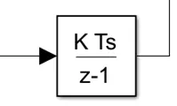
As name suggest that block is used as the integrator in the system in discrete manner. In the simulation it is used in the SOC sub system.
Constant block:
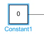
As name suggests that block is a constant block providing a particular value as a constant.
Although , the value can be controlled by many ways i.e., slider gain bar.
Electrical and mechanical references:
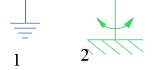
First one is Electrical reference, used as the reference point or ground point is the electrical system.
Second one is the mechanical rotating reference point. It is reference point in the mechanical system and act as reference in the system. Both of them are important in the system without them there will no reference that means there is no zero potential and for rotation there is no starting point for rotation.
Solver Configuration:
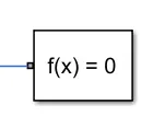
Solver configuration is essential in the simscape domain. It provides the different solver to solve various equation of the system during the execution of model.
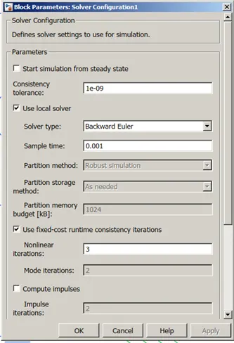
As shown in the block parameter the Backward Euler solver type is used for the sample time of 0.001 second.
PS-Simulink converter and Simulink- PS converter:
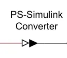
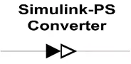
As name suggest the PS-Simulink converter is the communication path from Physical simscape blocks to Simulink block.
Similarly, the Simulink-PS Converter is the communication gate or path between Simulink block to physical simscape block.
Integrator:
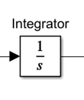
Integrator is simply do a integration of whatever input is given to the block.
Scope:
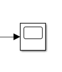
Scope is viewer of the signal. It is like DSO and CRO in the Simulink.
Simulation Model:
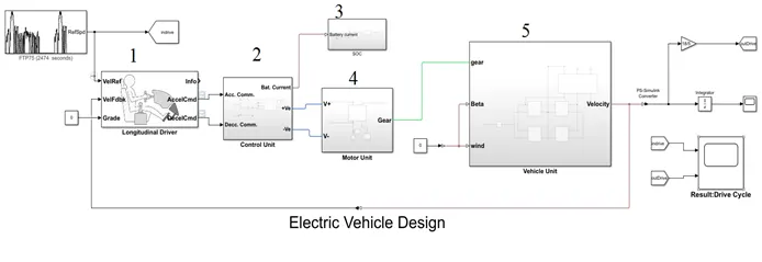
The Simulink model is connected like
- References and actual speed to longitudinal driver
- Control unit: controlled PWM and H- Bridge
- SOC measuring unit
- Motor unit: DC motor connected to vehicle
- Vehicle unit: Tire, vehicle body and output is velocity
Working:
Actual and reference speed are compared in the longitudinal driver and that produces the acceleration , deceleration and brake command. That command are given to the controlled voltage. Controlled voltage act as reference for Controlled PWM , that produces the PWM pulses according to the reference signal given.
That generated pulses are given to H- bridge and it produce the voltage and current for the motor to act accoring to reference speed. That H -bridge is connected to DC motor and drive line of vehicle. The battery SOC is also meaured from the H-bridge output terminal.
References and actual speed to longitudinal driver:
In this System the actual speed of the vehicle and the reference speed from the driver cycle is given to the longitudinal driver. The longitudinal driver is nothing but a PI controller which reduces the error between reference and actual signal.
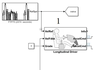
To reduce the error, the longitudinal driver produces brake and acceleration command, which can be send to the control unit.
Control Unit:
As name suggests the control unit is a unit in which controlling signals are generated to control the motor action. That control signals are produced due to the command given from the longitudinal driver.
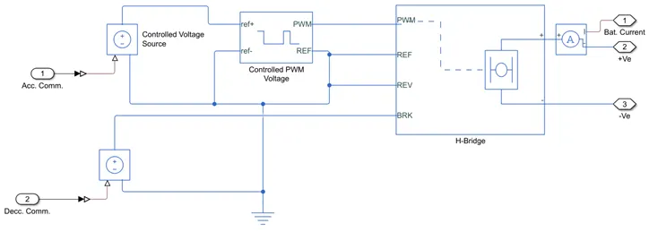
Control unit consists of controlled voltage source, controlled PWM, and H-Bridge. The acceleration or brake command are given to the controlled voltage source which produces the reference signal for the controlled PWM source. That controlled PWM pulses are given to the H- bridge to act according to the command.
SOC measuring unit:
SOC stands for states of charge of battery. This indicates that how much charge is still left out of the battery capacity.
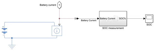
In H- bridge configuration the voltage source is configured as internal, hence to measure the SOC there must be other arrangement.
The battery used has capacity of 50 Ahr.
To measure SOC the battery current is required. For that current sensor is used. The output of current sensor measurement is given to the controlled current source, which is connected across the battery. This is because the current drawn from the internal voltage source will be replicated in that external battery.
Now, to measure the SOC , it is needed to decide the battery capacity in Ahr. Which is specified in that external battery.
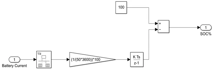
`I = (dq)/(dt)`
Therefore, `q = int_0^t I *dt (Ampere* sec)` or Coulomb
Battery capacity
`x Ah = 3600 A sec = x*3600` Coulomb
x= 50
Hence 50 Ahr = 50*3600 Coulomb = 18X10^4 C
Now to calculate SOC in real time, both the term can be divided to know how many percentage value of the total charges is being transferred from battery or to the battery.
`[q/ (x*3600)] * 100 %`
Now That percentage should be subtracted or added to 100% initial charge depending upon the current direction.
The above discussion is implemented in the simulation.
Motor unit: DC motor connected to vehicle:
Motor unit consists of a Permanent Magnet motor connected to the mechanical rotational shaft and the vehicle.
Vehicle unit: Tire, vehicle body and output is velocity
Vehicle unit consists of vehicle body and tire are connected together. That all parts are connected represent the vehicle assembled with different parts such as tires, vehicle body and all the transmission system.
Results:
As seen in the below plot the reference speed and vehicle output speed are plotted in the same graph..
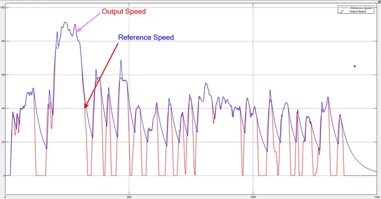
Here FTP75 driving cycle is used and running time for this is 1500 second. As seen the vehicle is almost following the reference speed. Although, vehicle is bad at braking or it couldn’t get enough time to decelerate and stop the vehicle.
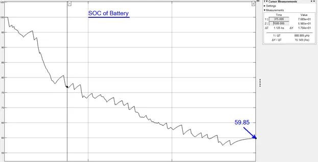
Next plot is the SOC of the battery, showing how much charge is used during the driving cycle.
As seen from the plot at the end of 1500 seconds the SOC remaining in the battery is 59.85%.
Here the regenerative braking effect also seen in the plot. During the braking the current gets reverse direction and that means it is charging and increase little bit charging of the vehicle.
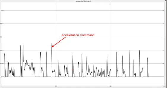
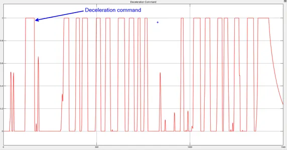
According to the driving cycle given from the FTP75 the acceleration and deceleration command are generated from the longitudinal driver. The maximum braking and acceleration command generated from the longitudinal driver is 1.
The acceleration and deceleration command from the longitudinal driver are given in below.
Next plot is the distance travelled by vehicle in the given period of driving cycle.
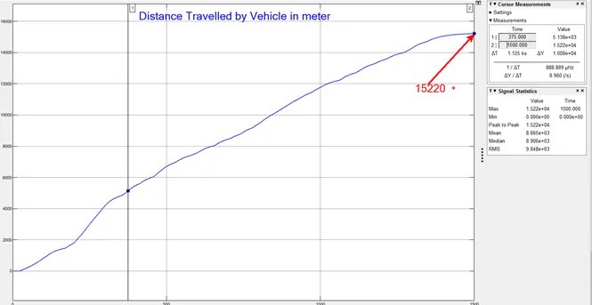
As seen from the below plot the distance travveled at the end of 1500 seconds is 15220 meter, that means 15.22 km.
Next scope output is the battery current from the H-bridge or say DC motor drawing current.
As seen here the current is variable and the amount of current is deped uon the vehicle load and speed. There is also negative region of current provide the regenerative braking.
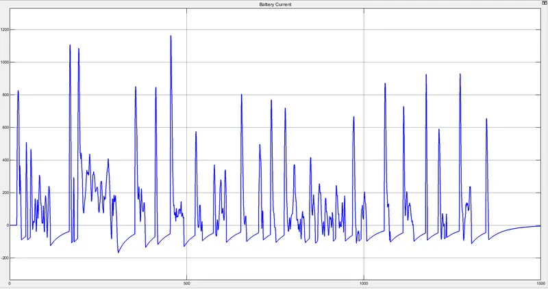
At some point the current crosses the zero line and becomes negative, that region is the regenerative braking where the current flows from load to back to the battery.
Conclusion:
From the above results and the discussion, it is concluded that the electrical vehicle is Designed with DC motor and with regenerative braking. The implemented electric vehicle follows the driving cycle properly. Although, the vehicle is bad at braking or couldn’t get enough time to stop from that such high speed. Battery State of Charge is also observed during discharging and charging through regenerative braking. At the end of 1500 seconds the SOC 59.85% is and distance travelled is 15.22km .