Final Project: Design of an Electric Vehicle
Design of Electric Vehicle
Theory -
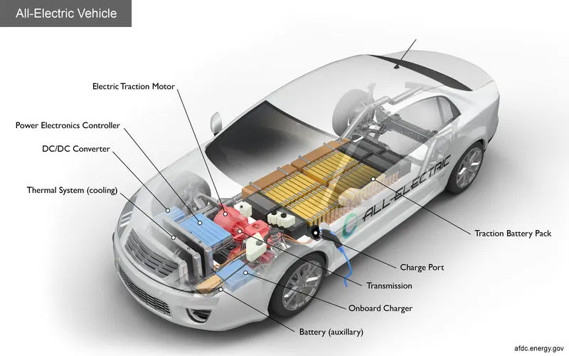
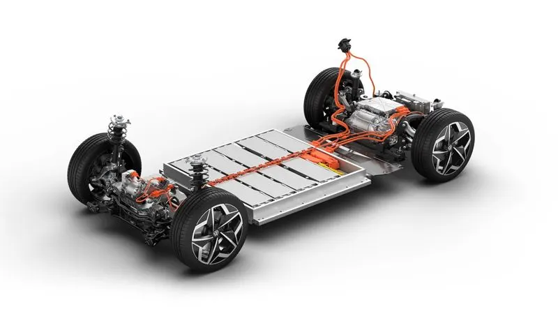
All-electric vehicles (EVs), also referred to as battery electric vehicles, have an electric motor instead of an internal combustion engine. The vehicle uses a large traction battery pack to power the electric motor and must be plugged in to a wall outlet or charging equipment , also called electric vehicle supply equipment (EVSE). Because it runs on electricity, the vehicle emits no exhaust from a tailpipe and does not contain the typical liquid fuel components, such as a fuel pump, fuel line, or fuel tank .
Key Component of Electric Vehicle -
Battery (all-electric auxiliary): In an electric drive vehicle, the auxiliary battery provides electricity to power vehicle accessories .
Charge port: The charge port allows the vehicle to connect to an external power supply in order to charge the traction battery pack .
DC/DC converter: This device converts higher-voltage DC power from the traction battery pack to the lower-voltage DC power needed to run vehicle accessories and recharge the auxiliary battery .
Electric traction motor: Using power from the traction battery pack, this motor drives the vehicle's wheels. Some vehicles use motor generators that perform both the drive and regeneration functions .
Power electronics controller: This unit manages the flow of electrical energy delivered by the traction battery, controlling the speed of the electric traction motor and the torque it produces .
Thermal system (cooling): This system maintains a proper operating temperature range of the engine, electric motor, power electronics, and other components .
Steps -
1) Tire (Magic Formula) -

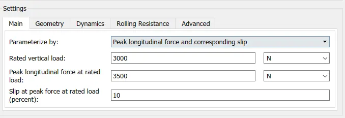
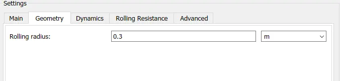
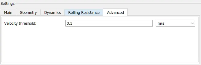
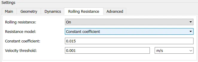
We start with designing the tires of the vehicle . Firstly four tires has been selected two for rears and two for front as shown in model design figure . The specifications of the tire is shown below ,
2) Vehicle Body -
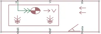
Represents a two-axle vehicle body in longitudinal motion. The block accounts for body mass, aerodynamic drag, road incline, and weight distribution between axles due to acceleration and road profile. The vehicle can have the same or a different number of wheels on each axle. Optionally include pitch and suspension dynamics or additional variable mass and inertia. The vehicle does not move vertically relative to the ground . The settings of the vehicle body is shown in the figure below ,
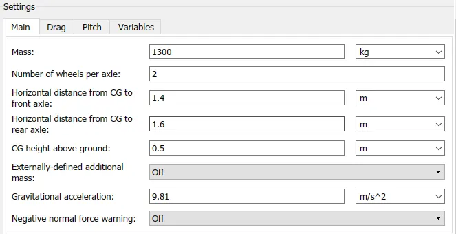
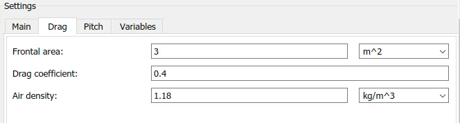
The value of wind is taken 2 m/s and Slope angle is considered Zero .
3) Gear Box -
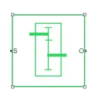
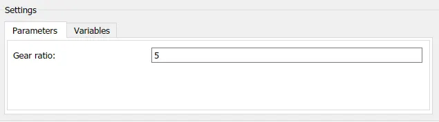
A gear ratio is the ratio of the number of rotations of a driver gear to the number of rotations of a driven gear .
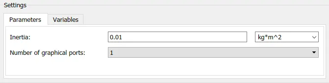
4) Inertia -

The block represents an ideal mechanical rotational inertia .
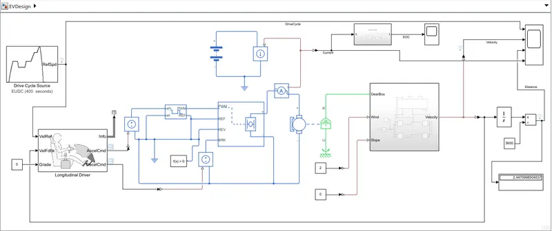
5) The final connections of these blocks is shown in figure down below ,
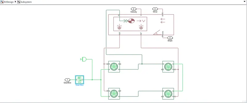
These blocks have been merged into a subsytem .
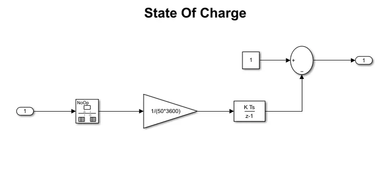
6) State Of Charge -
7) DC Motor -
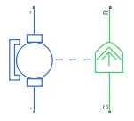
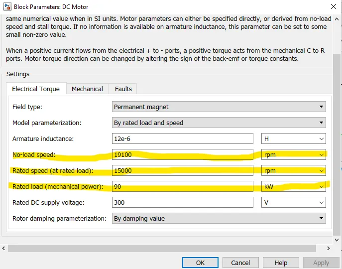
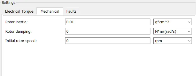
The advantages of this motor are easy speed control and it can also withstand a sudden increase in load . All these characteristics make it an ideal traction motor. The main drawback of DC series motor is high maintenance due to brushes and commutators. The specifications of DC motor is shown in figure down below . Some changes have been done which has been highlighted ,
8) H-Bridge -
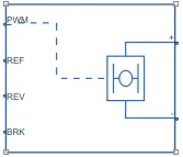
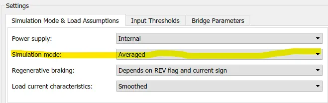
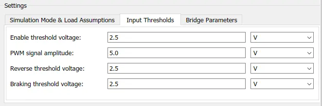
This block represents an H-bridge motor drive. The block can be driven by the Controlled PWM Voltage block in PWM or Averaged mode. In PWM mode, the motor is powered if the PWM port voltage is above the Enable threshold voltage. In Averaged mode, the PWM port voltage divided by the PWM signal amplitude parameter defines the ratio of the on-time to the PWM period. Using this ratio and assumptions about the load, the block applies an average voltage to the load that achieves the correct average load current. The Simulation mode parameter value must be the same for the Controlled PWM Voltage and H-Bridge blocks .
The simulation mode changed to Averaged so to simulate the model fastly .
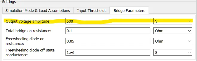
The output voltage amplitude value kept to 500 V .
9) Controlled PWM Voltage -
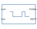
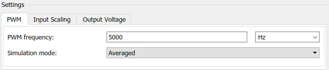
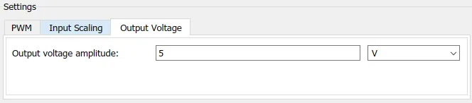
This block creates a Pulse-Width Modulated (PWM) voltage across the PWM and REF ports. The output voltage is zero when the pulse is low, and is equal to the Output voltage amplitude parameter when high. Duty cycle is set by the input value. Right-click the block and select Simscape->Block choices to switch between electrical +ref/-ref ports and PS input u to specify the input value . The PWM frequency is set to 5000 Hz and output voltage is set to 5 V .
10) Longitudinal Driver (mask) (link) -
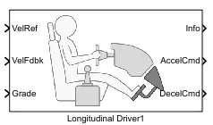
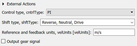
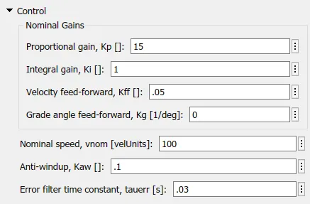
A parametric longitudinal speed tracking controller for generating normalized acceleration and braking commands based on reference and feedback velocities .
11) Drive Cycle -
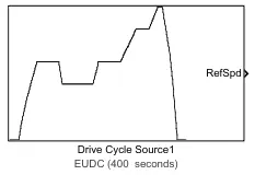
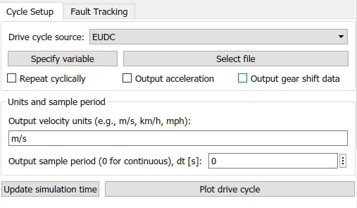
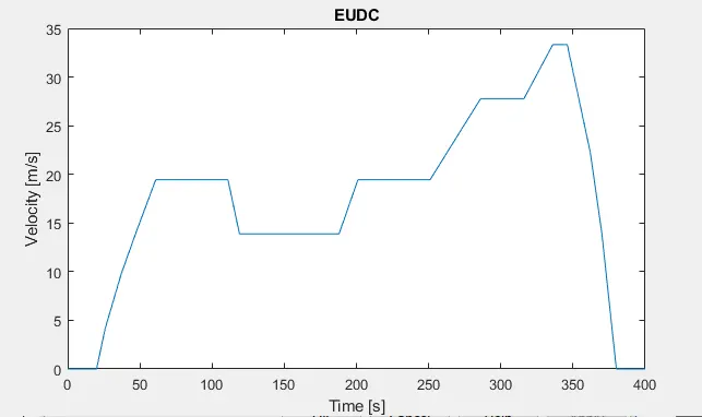
A driving cycle is a series of data points representing the speed of a vehicle versus time . There are many drive cycles . Here we have selected EUDC Drive Cycle . EUDC stands for Extra Urban Drive Cycle which is used to account more aggressive, high speed driving modes .
12) Controlled Voltage Source -
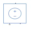
The block represents an ideal voltage source that is powerful enough to maintain the specified voltage at its output regardless of the current passing through it. The output voltage is V = Vs, where Vs is the numerical value presented at the physical signal port .
13) Current Sensor -
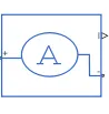
The block represents an ideal current sensor, that is, a device that converts current measured in any electrical branch into a physical signal proportional to the current .
14) Current Sensor -
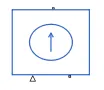
The block represents an ideal current source that is powerful enough to maintain the specified current through it regardless of the voltage across it .
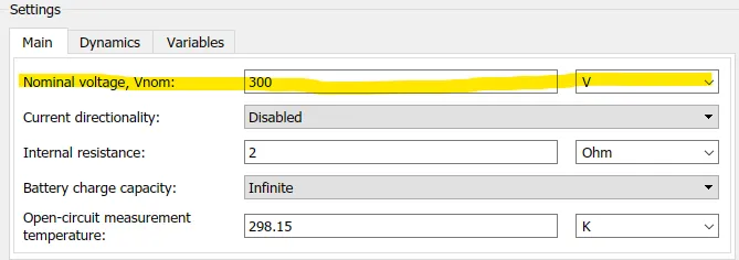
15) Battery -

The battery output voltage is kept to be 300 V and rest of the settings are kept unchanged .
16) Integrator -
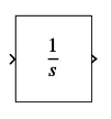
It is Continuous-time integration of the input signal .This block has been used for integrating velocity which will give us the Distance value .
RESULTS -
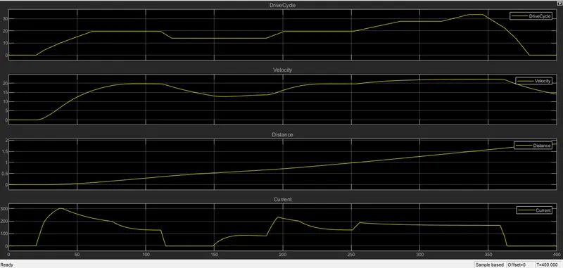
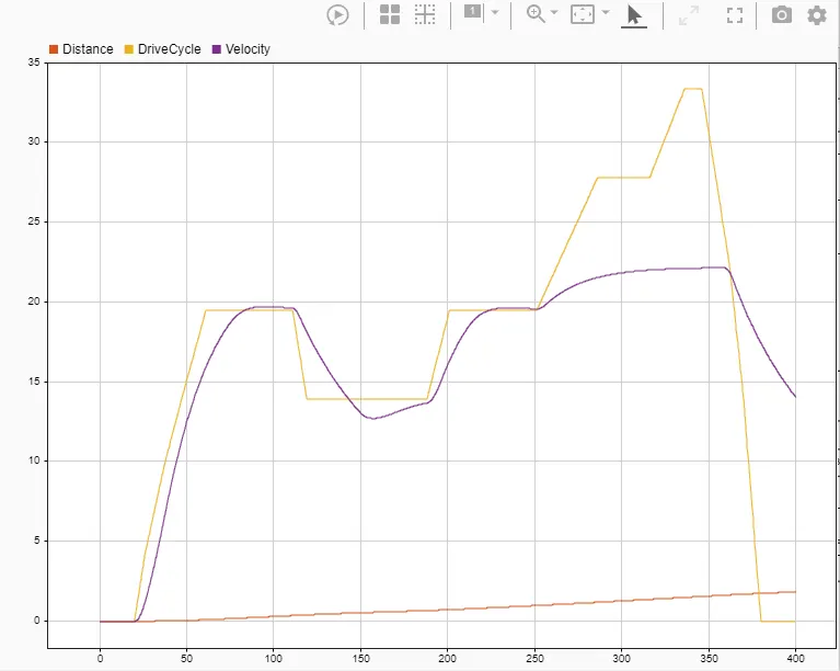
The ode15s solver has been selected . And the model has been run for 400 sec .
SOC -
Conclusion -
- The total distance covered by vehicle is 1.8 m/s at velocity 19.5 kmph depending upon EUDC Drive cycle and total time for simulation is 400 sec .
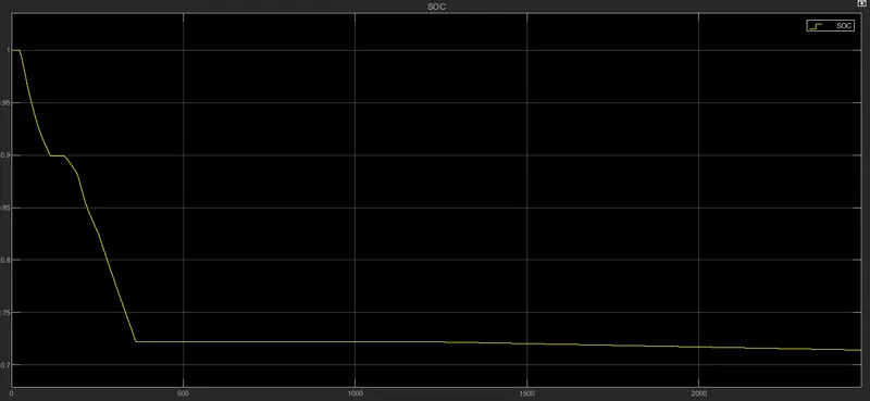
- The battery is having nominal voltage 300 V and we have calculated the state of charge .
- The battery starts discharging after 23 sec and discharge upto 400 sec .
- The peak current is 301.74 Amp and starts decreasing to -35.02 uA .