Final Project: Design of an Electric Vehicle
1. Title :-
Create a MATLAB model of electric car which uses a battery and a DC motor.
2. Introduction :-
An electric car has to be model with the help of blocks present in powertrain blockset in MATLAB-simulink .
The blocks used to modelled the electric car project are:-
- Transmission and differential (It is not available in matlab library but has to be modelled seperately) it contains tire (magic formula),vehicle body ,gear box block.
- DC motor
- H-bridge motor drive
- Controlled PWM voltage
- Longitudinal driver
- Drive cycle source
- Scope,display,solver,electrical refrence ,mechanical rotational refrence
- Current sensor,controlled voltage source from simscape library.
- PS-simulink and simulink-PS converter.
3. Workdone :-
The modelling of electric car project is as shown :-
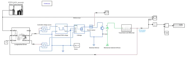
Functionality and parameterization of each block's in model are disscuss below:-
a. Transmission and differential :-
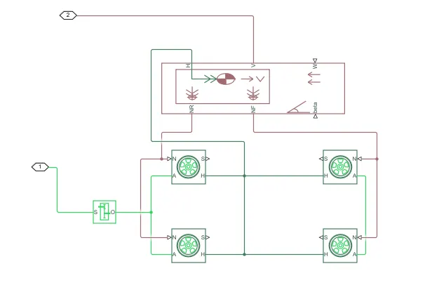
This is the modelling of transmission and differential block. As it contains tire,vehicle body and gear box.
We are using rear wheel drive as gear box is connected to axel of rear wheel.
Tire(magic formula) block has four terminal "N" is the input which is normal force applies on tire ,"A" axel,"H" hub and "S" is output which is releative slip between tire and road in this slip consider to 0.
Vehicle body block has six terminal they are "NR and NF" connected to N of rear and front tire respectively,"H" of all tire are common and connected to H of vehicle body."w and beta " represent wind velocity and grade in this case we consider to be 0.And "V" is the output velocity .
Gear ratio set as 5 and parameter of tire and vehicle body are set as it is(by default values)
b. DC motor :-
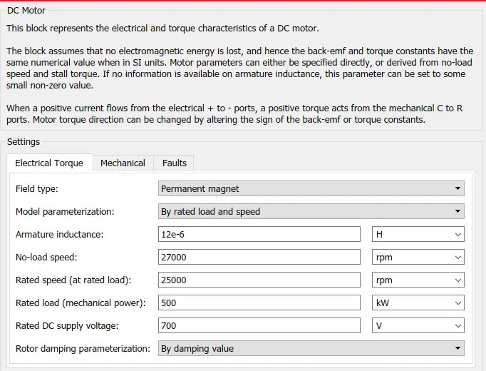
This are the specification of dc motor.
Field type selected as permanent magnet ,model parameterization as rated load and speed.
The most important point of selection is the supply volatge and capacity of motor . If not correct then vehical will not responds as per given input .
So, depending on desired input select the motor specification.
Here DC supply is set to 700 volt with no load and full load speed to be 27000 and 25000 RPM respectively for 500KW mechanical load.
Mechanical and fault parameter are not changed.
c. H-Bridge motor drive :-
It contains an power electronic converter (chopper circuit)which provides variable dc voltage at the output as per dc motor demanded.
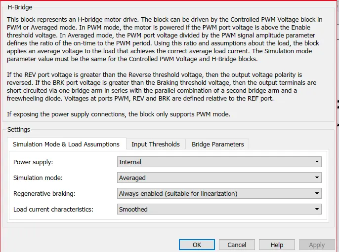
In this we can select power supply as internal and external .For simulation mode also two type averaged and PWM mode and regenerating option is also enable.
In this model we select the power supply as internal of simulation mode to be averaged.
The disadvantage of PWM mode is that it take more time to simulate because it takes the value at each and every instant of time and as compared to it,averaged mode is fast.
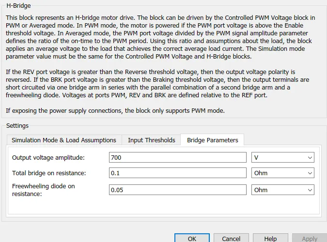
This is the output voltage of H-Bridge at 700 volt which is applied to dc motor armature terminal at rated load.As the speed changes the voltage applied to dc motor aslo changes as speed is directly proportional to voltage.other parameter is as it is.
H-Bridge block has four input PWM,REV,REF and brake.
d. Controlled pwm voltage :-
It has two input ref+ and ref- and depending on this PWM pulses are generated.
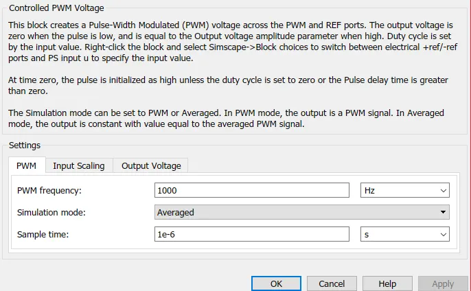
In this also simulation is set to averaged mode.
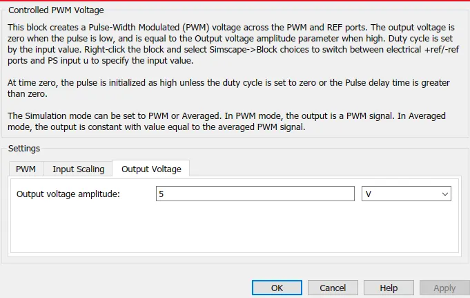
The amplitude of PWM voltage is set at 5 volt.
e Longitudinal driver :-
It contains PI controller .
In which input is refrence drive cycle,gradibilty,and vehicle feedback and output are acceleration command and decceleration command.
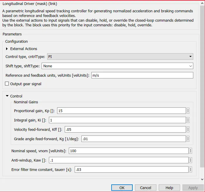
Here controller are set to PI and refrence and feedback velocity are in m/sec.And all gain constant are set as it is and grade is set to 0.
e. Drive cycle source :-
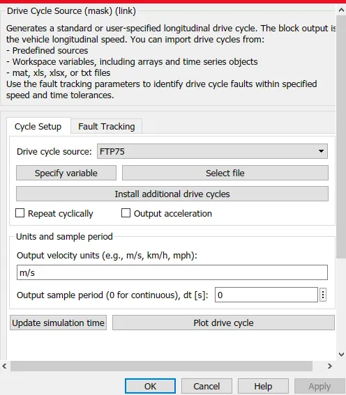
The FTP 75 is the drive cycle selected and its plot is as follows:-
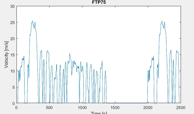
This is the plot of FTP75 drive cycle as refrence input with velocity in m/sec on yaxis and time in seconds on x-axis.
Working:-
- As we are given refrence input as drive cycle FTP75 in m/sec which is applied to longitudinal driver block .
- Longitudinal block contains PI controller. In this block the difference between refrence input and feedbck output in m/sec are calculated and this difference is error.
- The amount of error is given as input to thr PI controller which produces the actuating signals .And the output of block is acceleration and decceleration signal which ultimately depends on drive signal nature.
- The acceleration and decceleration commands are the physical signal that has to be apply to controlled pwm voltage block ,so it needs to be a convert from physical signal to electrical signal with help of controlled voltage source block in simscape.
- The output of controlled voltage source corresponds to acceleration command is given to PWM block which genrates the pwm pulses accordingly and given to PWM terminal of H-Bridge and controlled voltage source respective to deccelration command is directly given to brake terminal of H-bridge.
- So according to input of H-bridge the output volyage is applied to dc motor.
- The dc motor output is rotational whose torque is multiplied with help of gear box and then apply to axel of vehicle body which then results in vehicle movement.
4. Result :-
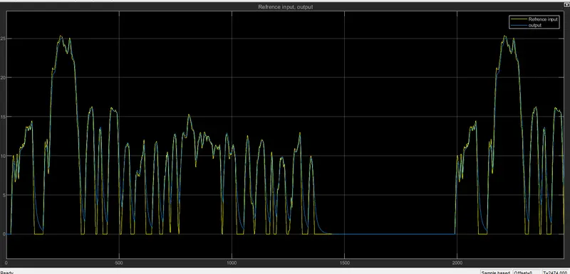
If we see this graph both yellow graph and blue graph almost coinside with each other it means the vehicle are tracking the refrence input correctly.
And selection of motor parameter are correct.
Yellow graph is refrence input and blue graph is output response of vehicle.
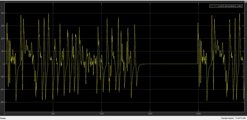
This the graph of current through dc motor . As the demand of vehicle varies the current demanded by dc motor varies.
Positive current represent acceleration and negative current represent regenerative braking while decceleration that is charging of battery.
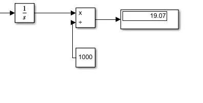
To calculate how much vehicle travel it can be calculated as above.
We have velocity in m/sec pass through integrator to get distance in meter to convert in km divide by 1000.
So we get 19.07 km as vehicle cover.
5. Conclusion :-
Above project on modelling of electric car are modelled in matlab-simulink and results are analysed.