Final Project: Design of an Electric Vehicle
The powertrain of an Electric Vehicle (EV) consists of an electric drive system with a battery serving as an energy buffer. Often there is only one electric machine, typically of three phase AC type, connected to the wheel shaft via a gearbox and a differential. However some applications may utilize several electric machines, e.g. hub wheel motors. The energy is stored chemically in a battery, which is electrically connected to the machine via a DC/AC power electronic converter accompanied by a control system. The control system controls the frequency and magnitude of the three phase voltage that is applied to the electric machine, and these are depending on the driver’s present request, which is communicated via the acceleration and/or brake pedal. In vehicle applications, it is usually desirable to keep the physical volume of the electric machine down. This can be done by designing it for higher speed levels. As a general design guideline a reduction in gear ratio towards the wheels, is inherently needed. Additionally, in order to give the left and right traction wheels a chance to spin at slightly different speeds during turning, there is also a need for a differential to be connected between the wheels.
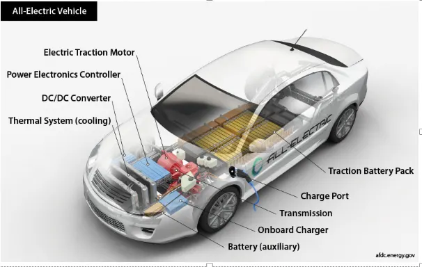
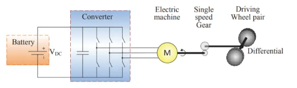
Key Components of an All-Electric Car [Ref 1]
Battery (all-electric auxiliary): In an electric drive vehicle, the auxiliary battery provides electricity to power vehicle accessories.
Charge port: The charge port allows the vehicle to connect to an external power supply in order to charge the traction battery pack.
DC/DC converter: This device converts higher-voltage DC power from the traction battery pack to the lower-voltage DC power needed to run vehicle accessories and recharge the auxiliary battery.
Electric traction motor: Using power from the traction battery pack, this motor drives the vehicle's wheels. Some vehicles use motor generators that perform both the drive and regeneration functions.
Onboard charger: Takes the incoming AC electricity supplied via the charge port and converts it to DC power for charging the traction battery. It also communicates with the charging equipment and monitors battery characteristics such as voltage, current, temperature, and state of charge while charging the pack.
Power electronics controller: This unit manages the flow of electrical energy delivered by the traction battery, controlling the speed of the electric traction motor and the torque it produces.
Thermal system (cooling): This system maintains a proper operating temperature range of the engine, electric motor, power electronics, and other components.
Traction battery pack: Stores electricity for use by the electric traction motor.
Transmission (electric): The transmission transfers mechanical power from the electric traction motor to drive the wheels.
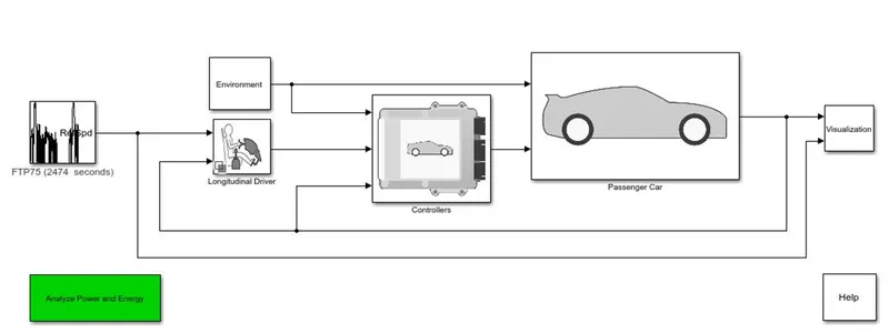
Base model considered for simulation
The below model shows the basic layout of an electric vehicle (referred from powertrain blockset), it consists of a drive cycle, environmental considerations, a driver, controller unit of the vehicle driving a passenger car. The inside locks of passenger car consists of electric plant made of battery and motor unit and a drive train plant consists of rotational inertia, driveshaft compliance, drive train configurations, differential an compliance, wheels and brakes, those which makes up a mechanical structures of the vehicle and finally leading to vehicle output interface).
Next Steps
Converting the above model into an actual vehicle model by developing the relevant physical vehicle, motor and controller, battery subsystem and state of charge estimate model, speed & distance estimation models and drive cycles . The new developed model is given below.
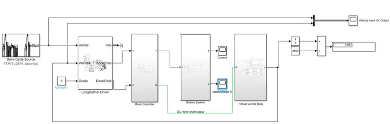
Further moving forward each of the individual blocks in the above figure are given in detail with their spec and circuit diagrams.
Virtual Vehicle Body
Following are the default settings and assumptions of the components that are considered for physical model of the vehicle
- Gear Teeth ration = 3.7
- Block parameters of tire
+ tire vertical load = 4000N
+ gravity = 9.81m/s^2
+wind velocity = 1 m/s (assumed value)
+hill climbing angle (beta) = 0 (assumed value)
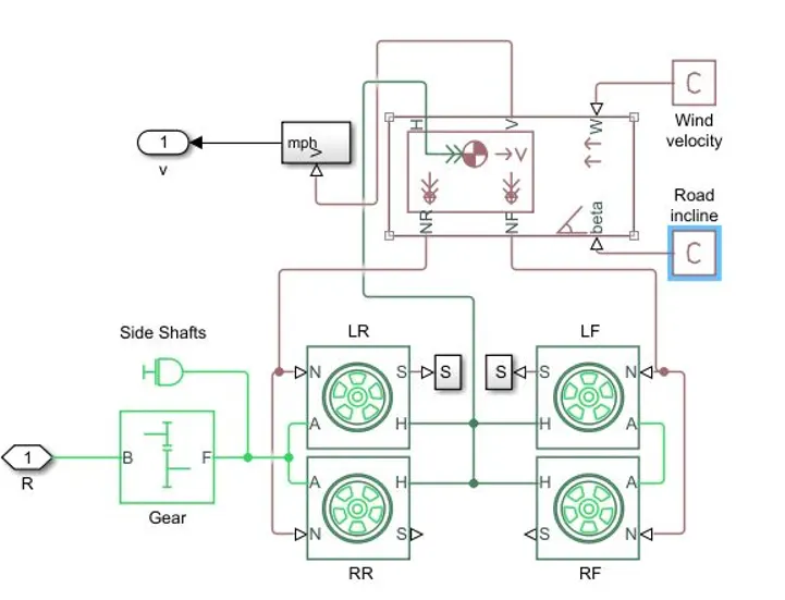
Fig-1: Virtual model of a vehicle (a subsystem to be integrated)
- Motor and Controllers: Key Components required to build a motor and controller are
- PWM voltage generator (controlled)
- H-Bridge
- Current sensor
- voltage source (controlled)
- DC motor (with both electrical and mechanical sides)
Note: these components are chosen from simscape and are connected through 'PS converter' to the Simulink components wherever required
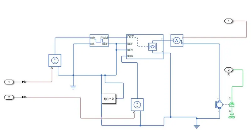
Fig-2: Motor model (a subsystem to be integrated)
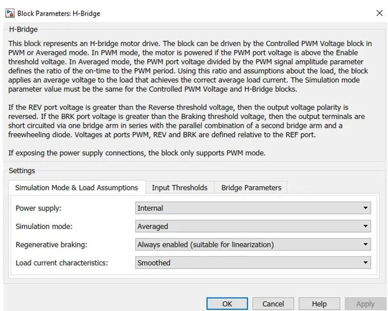
The default setting values of the components in H bridge and DC motor are given below
H Bridge
DC Motor
Field type: Permanent magnet
model parameterisation: by rated load and speed
armature inductance : 12e^-6 H
No load speed : 7000 rpm
rated speed: 3000rpm
rated load: 60KW
DC supply: 300V
Controlled PWM voltage
PWM frequency = 3000 Hz
Input scaling : input voltage for 0% duty cycle = 0V, input voltage for 100% duty cycle = 5V
Output voltage: output voltage amplitude = 5V
Controlled voltage source
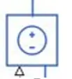
To provide the necessary voltage that is powerful to maintain the output irrespective of the current through it's subsystem controlled voltage sources.
Also these voltage sources are grounded conveniently
Solver function f(x) = 0 is used to solve the relevant model equations
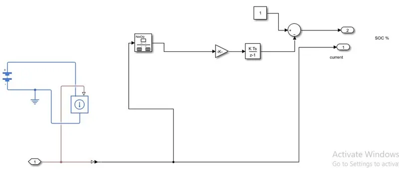
Battery System: A battery model with an SoC (state of charge) and Current estimation is given below
- The battery system is made up of following components
- DC voltage source (nominal voltage = 300V, internal resistance = 0.2ohm)
- Controlled current source
- SOC estimator (Integrator --> to handle data transfer and integrate the values of current signal, Gain factor --> to multiply and divide the signal coming from integrator, constant --> assumption that the battery is 100% charged always (1 to 0 scale), subtractor --> to have the SoC decline over a period of drive)
Longitudinal Drive cycle
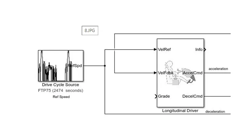
The longitudinal drive block is used to give acceleration and deceleration commands to the motor controller using reference velocity 'Velref' (actual drive cycle) and feedback velocity ' VelFdbK (from vehicle body).
if the reference velocity is greater than the feedback, then the acceleration commands shall be guided, else the other way. In this case the Greadability is assumed to be Zero
Drive cycle
A drive cycle is the two dimensional matrix of time vs. velocity. This reference is drive cycle is used to drive the model of an electric vehicle. There are different ways of choosing a drive one is by means of selecting the available drive cycle data from the Simulink library & the other way is to choose our own drive cycle based on the experience or available data
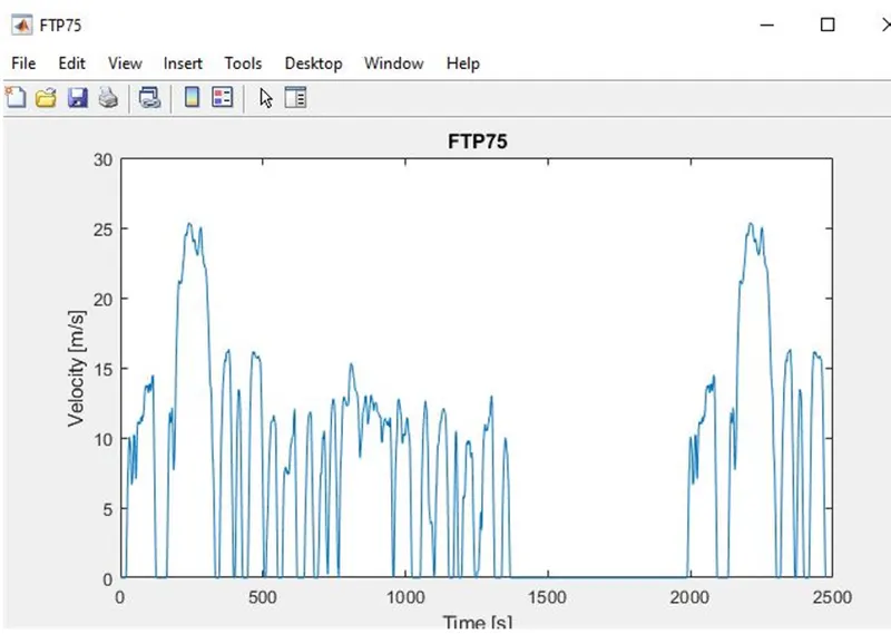
With these settings, the simulations was executed and follwoing observations were seen.
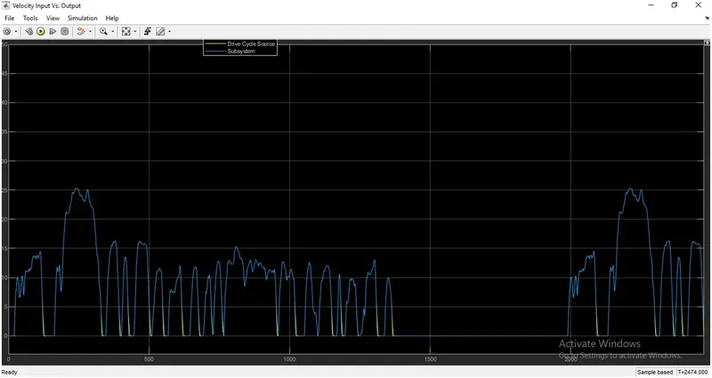
1. Input vs output velocity (comparions of drive cycle sources with the actual model output)
yellow line represents drive cycle source
blue line represents the outcome of the EV model
Output follows input for selected parameter values
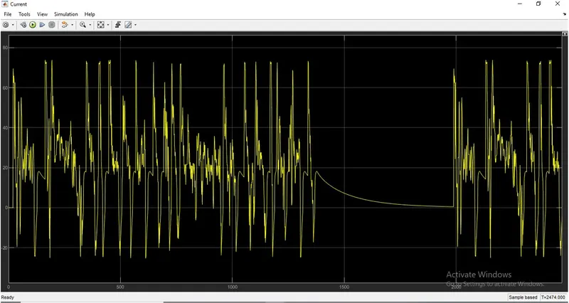
2. Current Demand by the DC Motor from the Battery is shown below
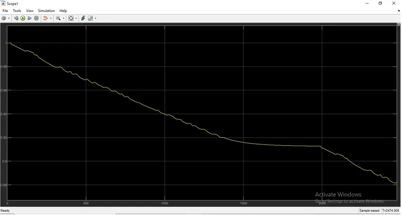
3. State of Charge of the Battery during charging and discharging is given below
Conclusion
A MATLAB model of electric car which uses a battery and a DC motor was built using simulink libraries (mainly powertrain block set). A complete information of System level configurations, Model parameters and Results are reported as above
To Conclude:
- Output velocity of the model is mapped against the input drive sources and for selected parameters the output follows the input drive cycle. In case of gradient considerations, the output velocity might not catch at the peaks
- SoC (state of charge) demand over the drive cycle is observed both w.r.t charge depletion at demand and charging during regenerative braking
- Current draw pattern observed due to motor demand during acceleration and deceleration.
- Actual model is attached with this submission