Final Project: Design of an Electric Vehicle
Electric Vehicle
An electric vehicle (EV) is a vehicle that uses one or more electric motor propulsion. It can be powered by a collector system, with electricity from extravehicular sources, or it can be powered autonomously by a battery.
Electric Vehicles first came into existence in the mid-19th century, when electricity was among the preferred methods for Motor vehicle propulsion, providing a level of comfort and ease of operation that could not be achieved by the gasoline cars of the time. Internal Combustion Engines were the dominant propulsion method for cars and trucks for about 100 years, but electric power remained commonplace in other vehicle types, such as trains and smaller vehicles of all types.
In the 21st century, EVs have seen recovery due to technological developments, and an increased focus on renewable energy and the potential reduction of Transportation impact on climate change and other environmental issues.
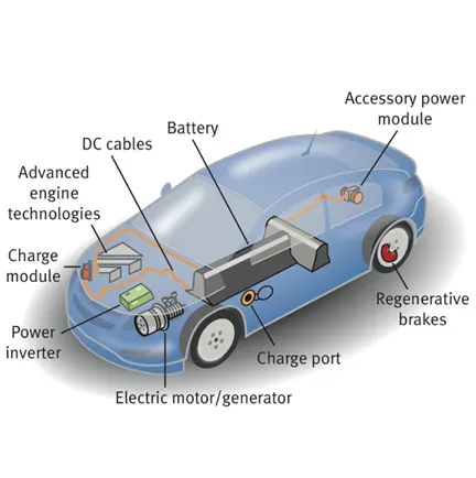
Figure (1): Electric Car and its Components
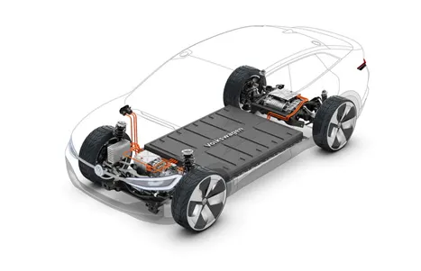
Figure (2): EV connected to the Battery
There are two types of EV technology Pure Electric and Hybrid
Fully Electric Car
The main parts in an electric car are a rechargeable battery, controller and electric motor. First, the battery is powered and then the controller converts the current from DC-AC so that it can be used by the motor. The motor converts electrical energy to mechanical energy.
Hybrid Car
The same technology exists in hybrid cars, alongside a small gasoline engine running a generator. This powers the car at cruising speed, and batteries provide extra power when accelerating. Batteries can recharge themselves when the car is decelerating or standing still. Hybrid technology means that your petrol goes much further, saving you money and reducing environmental impact.
Some Important Components of Electric Vehicle:
1.Motor or Electric Traction Motor(D)
The Induction motor that converts Electrical energy into Mechanical energy. A three-phase, four-pole induction motor is made of two main parts a stator and a rotor. The stator is made of three parts a stator core, conducting wire, and frame. The stator core is a group of steel rings that are insulated from one another and then laminated together these rings include slots on their inside that the conducting wire will wrap around to form the stator coils. Simply put, in a three-phase induction motor, there are three different wire types like Phase 1, Phase 2, and Phase 3. Each wire type is wrapped around the slots on opposite sides of the inside of the stator core. Once the conducting wire is in place within the stator core, the core is placed within the frame. The Electric vehicle uses the Brushed type DC induction motor and Brushless DC Induction motor. The Brushless DC Induction motor most popular used in Electric vehicle. The stator of the 3-ɸ induction motor and DC brushless motor are similar. The main difference between two machines is with the rotor. The DC brushless motor has a Stator and Rotor. These two components are important to any machine. The rotor includes two or more permanent magnets that generate a magnet field around it. This magnet field enters the stator core interacts with current flowing within the windings to produce the torque between the rotor and stator. When the rotor starts rotates the necessary magnitude and polarity of the stator currents be continuously varied then torque remains constant. When a 3-phase induction motor is connected to 3-ɸ power, the motor requires high starting torque under load condition. A brushless DC motor produces no starting torque when directly connected to fixed frequency utility power.
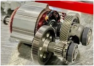
figure (3): Traction motor
2.Reducer or Transmission
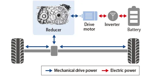
A reducer adjusts the number of revolutions by the motor and conveys those revolutions to the tires (drive shaft). The function of the reducer is equivalent to a conventional transmission. This gear box inherits the DNA of EV reducers to support e-POWER, a completely new innovation in EVs. The compact and high-efficiency gear box adds a power-generating multiplier to the reducer which supports motor drive. Through combination with a generator engine, this technology balances a new feeling of enjoyment in driving and outstanding fuel efficiency.
3.Battery(A)
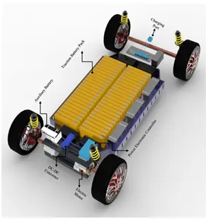
A Lithium-ion (Li-ion) battery is a type of rechargeable battery used in electric vehicles and a number of portable electronics. They have a higher energy density than typical lead-acid or nickel-cadmium rechargeable batteries. Lithium is also the lightest of all metals. Lithium-ion (Li-ion) batteries contain no lithium metal, they contain ions. For those wondering what an ion is, an ion is an atom or molecule with an electric charge caused by the loss or gain of one or more electrons. Battery electric vehicles (BEVs) operate only on stored electricity, and their main components consist of a high-voltage battery, one or more electric motors either Alternating current [AC] or Direct current [DC], and a controller to manage the power electronics. Compared with ICEs, which deliver their peak torque within a limited range of engine rpm, the electric motor is able to deliver a constant and high torque over a broad range of speeds from zero kmph thus, most BEVs neither need a reduction gearbox nor do they require the increasingly complex engine management systems that have been added to ICEs and their transmissions to comply with emissions legislation while retaining drive-ability. As a result, the complete EV drive train is less complex, compared with conventional vehicles with ICE.
Battery Management System
The main functions of a Battery Management System for electric vehicles are:
Battery protection in order to prevent operations outside its safe operating area.
Battery monitoring by estimating the battery pack State of Charge (SoC) and State of Heealth (SoH) during charging and discharging. Battery optimization thanks to cell balancing that improves the battery life and capacity, thus optimizing the driving range for hybrid (HEV), plug-in (PHEV) and full electric vehicles (BEV). The battery can be rechargeable into two ways. If the vehicle is deceleration or braking the motor acts as a generator it can applied the regenerative braking than the battery will charge to some extent. From the On Board Charger single phase AC supply connected to the battery.
4.Electric Power Control Unit (EPCU)
Power Inverter(B)
The inverter function to change the direct current (DC) on the battery into an alternating current (AC) and then this alternating current is used by an electric motor. In addition, the inverter on an electric car also has a function to change the AC current when regenerative braking to DC current and then used to recharge the battery. The type of inverter used in some electric car models is the bi-directional inverter category. The inverter can change the speed at which the motor rotates by adjusting the frequency of the alternating current. It can also increase or decrease the power or torque of the motor by adjusting the amplitude of the signal.
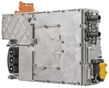
DC – DC Converter
Converts fixed dc input voltage to a controlled dc voltage. The batteries of an electric vehicle typically output several hundred volts of DC. The electric components inside the vehicle vary in their voltage requirements, with most running on a much lower voltage. This includes the radio, dashboard readouts, air conditioning, and in-built computers and displays. In electric vehicles which use a DC motor, actually running the motor can use up to three times the voltage provided by the battery. A simplified step-down converter work by generating a series of on-off pulses, and then using a combination of inductors and capacitors to smoothen this into a consistent DC signal, whose current is constant and whose voltage is determined by the duty cycle (that’s the duration of ‘on’ states relative to “off” ones).
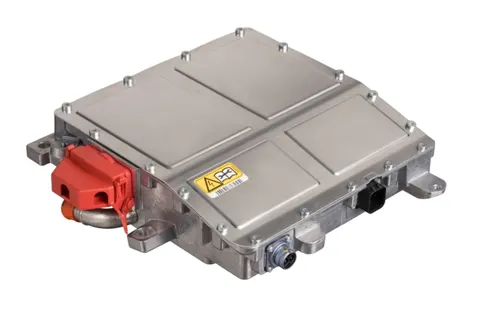
Controller (C)
The main function of the controller is as a regulator of electrical energy from batteries and inverters that will be distributed to electric motors. While the controller itself gets the main input from the car pedal which is set by the driver. This pedal setting will determine the frequency variation or voltage variation that will enter the motor, and at the same time determine the car’s speed. In brief, this unit manages the flow of electrical energy delivered by the traction battery, controlling the speed of the electric traction motor and the torque it produces. This component will determine how electric car work.
Thermal System – Cooling
This system maintains a proper operating temperature range of the engine, electric motor, power electronics, and other components.
Working of the Electric Car
When the car pedal is pressed, then Controller [C] takes and regulates electrical energy from batteries [A] and inverters [B] With the controller set, the inverter then sends a certain amount of electrical energy to the motor (according to the depth of pressure on the pedal) Electric motor [D] converts electrical energy into mechanical energy (rotation) Rotation of the motor rotor rotates the transmission so the wheels turn and then the car moves.
MATLAB Modelling
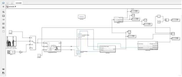
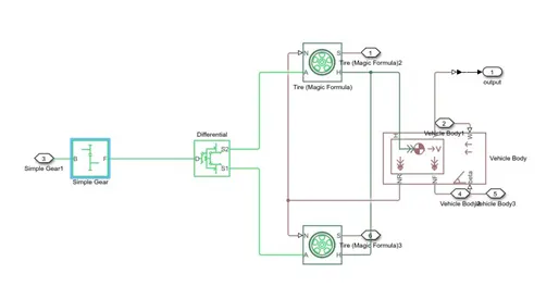
The above figure represents the block diagram of electric vehicle. The vehicle is model as per the block diagram of EV.
Modeling of Vehicle Body
In the vehicle body subsystem the Simulink blocks are used as simple gear, differential, tire, vehicle body.
The vehicle body represents a two-axle vehicle body in longitudinal motion. The block accounts for body mass, aerodynamic drag, road incline, and weight distribution between axles due to acceleration and road profile. The vehicle can have the same or a different number of wheels on each axle. Optionally include pitch and suspension dynamics or additional variable mass and inertia. The vehicle does not move vertically relative to the ground. Connection H is the mechanical translational conserving port associated with the horizontal motion of the vehicle body. The resulting traction motion developed by tires should be connected to this port. Connections V (Velocity), NF, and NR are physical signal output ports for vehicle velocity and front and rear normal wheel forces, respectively. Wheel forces are considered positive if acting downwards. Connections W and beta are physical signal input ports corresponding to headwind speed and road inclination angle, respectively. Here I have assumed vehicle mass as 600Kg, frontal area as 2 m2, Drag coefficient as 0.25.
Tire
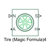
Tire represents the longitudinal behavior of a highway tire characterized by the tire Magic Formula. The block is built from Tire-Road Interaction Wheel and Axle blocks. Optionally, the effects of tire inertia, stiffness, and damping can be included. Connection A is the mechanical rotational conserving port for the wheel axle (A). Connection H is the mechanical translational conserving port for the wheel hub (H) through which the thrust developed by the tire is applied to the vehicle. Connection N is a physical signal input port that applies the normal force (N) acting on the tire. The force is considered positive if it acts downwards. Connection S is a physical signal output port that reports the tire slip (S).
Simple Gear
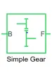
Simple Gear represents a fixed-ratio gear or gear box. No inertia or compliance is modeled in this block. Connections B (base) and F (follower) are mechanical rotational conserving ports. Specify the relation between base and follower rotation directions with the Output shaft rotates parameter.
Controller Subsystem
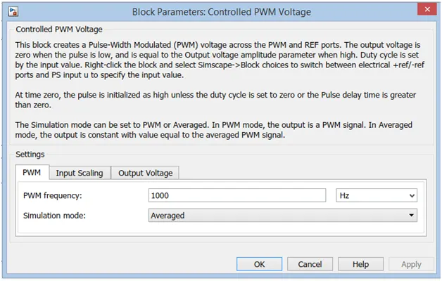
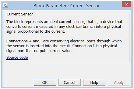
In the Controller subsystem the Simulink blocks are used as Dc motor, H-bridge, controlled pwm voltage source, solver configuration, electrical reference, mechanical rotational reference.
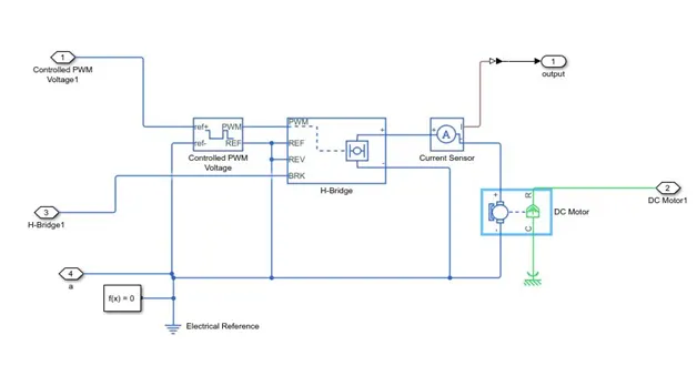
H-bridge
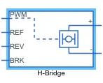
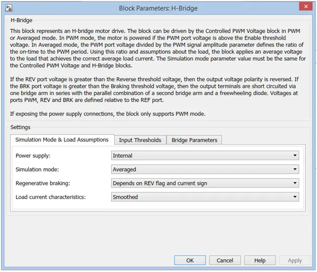
Here I have assumed the input thresholds values of H-bridge as threshold voltage, reverse and braking threshold voltage as 0.0001 and pwm signal amplitude as 1, output voltage parameters as 50v.
Controlled PWM voltage source

Current sensor

Longitudinal Driver
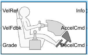
A parametric longitudinal speed tracking controller for generating normalized acceleration and braking commands based on reference and feedback velocities. The output of the Acceleration command is connected to the controlled pwm voltage source and the output of the Deceleration command is connected to the braking.The input of the velocity reference is from the driving cycle and velocity feedback is connected to the actual velocity of the vehicle. Here I am considering the grade as 0.
Battery Subsystem
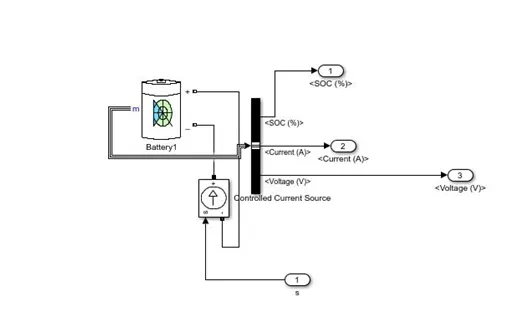
The battery SOC (State of Charge) is charge whenever the engine is ON & whenever the pps is sufficiently charge to the certain value the engine turn OFF.
Results
Battery SOC%
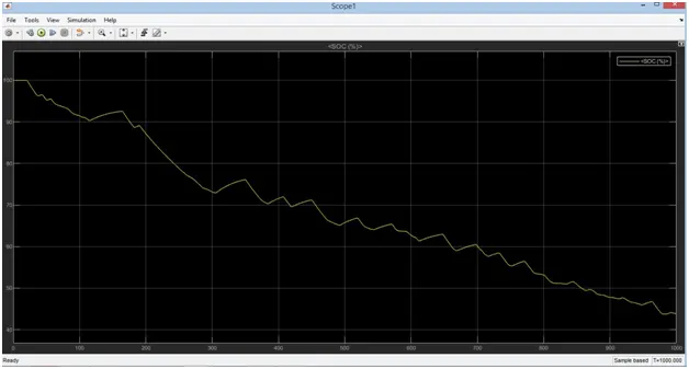
The battery has discharge non-linearly for the 110 seconds and Battery has charge and discharge at according to the feedback.
Battery Current
Battery Voltage
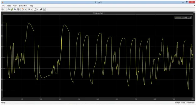
FTP75 Driving Cycle
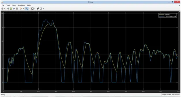
The velocity of the vehicle is also most matched with the given input.
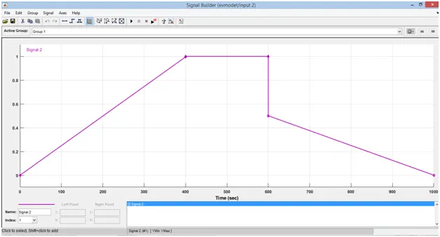
When the SIGNAL BUILDER is given as Input
The velocity of the vehicle is increase to the maximum upto 400 seconds and next 200 seconds the vehicle is constant and remaining 400 seconds the velocity is decrease to 0.5 amplitude.
Battery SOC
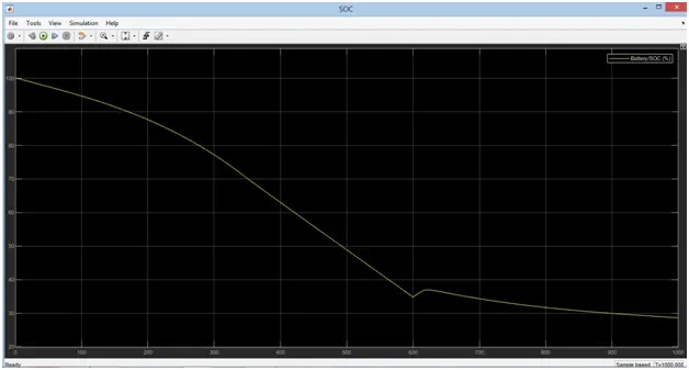
The Battery has discharge non-linearly for first 400seconds and after the battery discharge linearly and remaining 400seconds the battery has charge and discharge at according to the feedback.
Vehicle Velocity
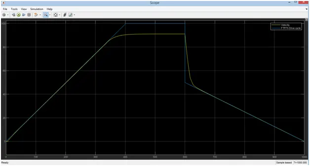
The Actual speed is trying to follow the reference speed is given to the signal builder and the averaged is of 50km/hr. To calculate the average speed manually divides distance by time. The distance is 13.41 km/hr for 1000seconds.
Conclusion
This is about Modeling of Electric Vehicle using Simulink we can use the simulation to see how the different type of motors and controllers are performing. Thus the MATLAB model of electric car which uses a battery and a DC motor has been simulate successfully with FTP75 Driving cycle and Signal Builder.