Final Project: Design of an Electric Vehicle
PROJECT: DESIGN OF AN ELECTRIC VEHICLE
AIM:
DESIGN OF AN ELECTRIC VEHICLE USING MATLAB SIMULATION
OBJECTIVE:
- SYSTEM-LEVEL CONFIGURATION
- MODEL PARAMETER
- RESULT
- CONCLUSION
ABSTRACT:
Nowadays electric vehicles are making revolutionary in the history of fuel vehicles like petrol and diesel. Electric vehicles are also known as EV's, the electric motors are very efficient using 90-95% of the input energy to power the movement of the vehicle and offer Zero vehicle emission driving. But the use of batteries poses the two main challenges for battery electric vehicles (BEV) The cost and driving range.
The present design of the Electric Vehicle model for this project is taken from BATTERY ELECTRIC VEHICLE (BEV), Here the battery is the primary source of fuel to operate the motor, and DC MOTOR is connected to run the propulsion to the vehicle through the simple gearbox. The vehicle body of the car is connected to tires of the front and rare axels to move the vehicle through the gearbox.
WHAT IS AN EV ( ELECTRIC VEHICLE):
An electric vehicle (EV) is a vehicle that uses one or more electric motors or traction motors for propulsion. An electric vehicle may be powered through a collector system by electricity from off-vehicle sources or may be self-contained with a battery, solar panels, fuel cells, or an electric generator to convert fuel to electricity.
TYPES OF ELECTRIC VEHICLES:
- There are two main types of electric vehicles (EV):
- Battery electric vehicles (BEV):
- The Battery electric vehicle uses only batteries for energy storage and must be plugged in to be recharged.
- Most current models of BEV do not store enough energy to provide a “normal” driving range and are limited to below 250 km (160 miles) per recharge. However, some new and forthcoming models offer substantially more range, up to 400 km.
- Regarding on-going cost reductions of batteries have helped enable the growth of EV's
- Plug-in hybrid electric vehicles (PHEV):
- The Plug-in hybrid electric vehicle has both batteries and liquid-fuel storage and refueling systems.
- PHEVs already offer 500 km or more due to the availability of their liquid-fuelled internal combustion engine. Both technologies are expensive, with battery costs estimated at around USD 350/kWh in 2015 and the cost of a hybrid system of several thousand dollars in PHEVs
- The Plug-in hybrid electric vehicle has both batteries and liquid-fuel storage and refueling systems.
- Battery electric vehicles (BEV):
SYSTEM-LEVEL CONFIGURATION:
- DRIVING CYCLE:
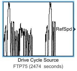
- The Drive Cycle Source block generates a standard or user-specified longitudinal drive cycle. The block output is the specified vehicle longitudinal speed, which you can use to:
- Predict the engine torque and fuel consumption that a vehicle requires to achieve desired speed and acceleration for a given gear shift reference.
- Produce realistic velocity and shift references for closed-loop acceleration and braking commands for vehicle control and plant models.
- Study, tune, and optimize vehicle control, system performance, and system robustness over multiple drive cycles.
- The plot for the FTP75 Drive Cycle Source is shown below,
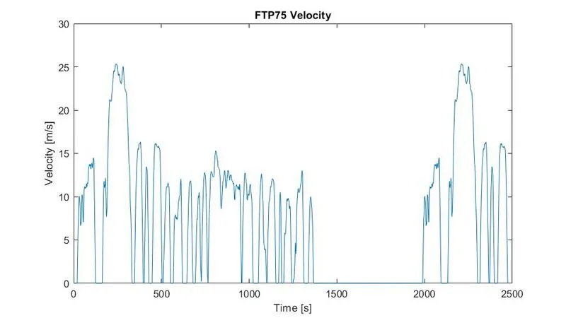
- The Time in seconds at the x-axis and Velocity in meters per second at the y-axis. At which the plot shows the acceleration of the vehicle and deceleration of the vehicle for the period of 2474 seconds in which approx 41.2 minutes. The vehicle will run by using this drive cycle source.
- The Drive Cycle Source block generates a standard or user-specified longitudinal drive cycle. The block output is the specified vehicle longitudinal speed, which you can use to:
- LONGITUDINAL DRIVER:
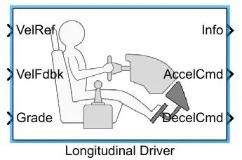
- The Longitudinal Driver block implements a longitudinal speed-tracking controller. Based on reference and feedback velocities, the block generates normalized acceleration and braking commands that can vary from 0 through 1. You can use the block to model the dynamic response of a driver or to generate the commands necessary to track a longitudinal drive cycle.
- In the Longitudinal Driver block there some types of control type parameters to specify
- PI: Proportional-Integral (PI) control with tracking windup and feed-forward gains
- Scheduled PI: PI control with tracking windup and feed-forward gains that are a function of vehicle velocity.
- Predictive:
- controller: PI Speed-Tracking:
- The control type to PI or scheduled PI, the block implements proportional-integral (PI) control with tracking windup and feed-forward gains. For the scheduled PI configuration, the block uses feed-forward gains that are a function of vehicle velocity.
- To calculate the speed control output, the block uses these equations.
-
Setting
Equation PI
`y=(K_(ff))/(v_(nom))*v_(ref)+(K_pe_(ref))/(v_(nom))+int((K_ie_(ref))/(v_(nom))+K_(aw)e_(out))dt+K_gθ`
Scheduled PI
`y=(K_(ff)(v))/(v_(nom))*v_(ref)+(K_p(v)e_(ref))/(v_(nom))+int((K_i(v)e_(ref))/(v_(nom))+K_(aw)e_(out))e_(ref)dt+K_g(v)θ` - So in longitudinal Driver block in this design to control the PI speed Tracking we use PI controller instead of Scheduled PI controller because for smooth simulation and less time-consuming.
-
- CONTROLLER:
- H-BRIDGE CONTROLLER:
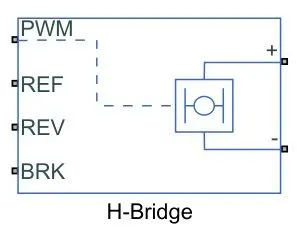
- The H-Bridge block represents an H-Bridge motor driver. For H-Bridge it has Two different Power supply Internal and External. Now for this power supply, it goes with the Internal power supply.
- In Internal power supply, it deals with PWM
- The H-Bridge block output is a controlled voltage that depends on the input signal at the PWM port. If the input signal has a value greater than the Enable threshold voltage parameter value, the H-Bridge block output is on and has a value equal to the value of the Output voltage amplitude parameter. if it has a value less than the Enable threshold voltage parameter value,
- The block maintains the load circuit using one of the following three Freewheeling modes Options:
- One semiconductor switch and One freewheeling diode
- Two freewheeling diode
- Two semiconductor switches and One freewheeling diode
- The signal at the REV port determines the polarity of the output.
- If the value of the signal at the REV port is less than the Reverse threshold voltage parameter value, the output has positive polarity.
- If the value of the signal at the REV port is higher than the Reverse threshold voltage parameter value, the output has negative polarity.
- Braking mode is invoked when the voltage presented at the BRK port is larger than the Braking threshold voltage.
- CONTROLLED PWM VOLTAGE:
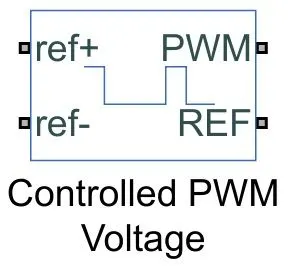
- The Controlled PWM Voltage block represents a pulse-width modulated (PWM) voltage source. This block has two modeling variants, accessible by right-clicking the block in your block diagram and then selecting the appropriate option from the context menu, under Simscape - Block choices:
- Electrical input ports: The block calculates the duty cycle based on the reference voltage across its ref+ and ref-ports. This modeling variant is the default.
- PS input: Specify the duty cycle value directly by using an input physical signal port.
- Electrical input ports: The block calculates the duty cycle based on the reference voltage across its ref+ and ref-ports. This modeling variant is the default.
- Here in Controlled PWM Voltage, it goes with Electrical input ports for this modeling.
- For Electrical input ports The variant of this block the demanded Duty cycle is `(V_(ref)-V_(min))/(V_(max)-V_(min))*100%`
- where,
- `V_(ref)`is the reference voltage across the ref+ and ref- ports.
- `V_(min)`is the minimum reference voltage.
- `V_(max)`is the maximum reference voltage.
- where,
- Use a fixed-step or local solver and the discrete-time switching event type we going to use, So we can use the SOLVER CONFIGURATION block to calculate all the multiple simulation step sizes.
- For Electrical input ports The variant of this block the demanded Duty cycle is `(V_(ref)-V_(min))/(V_(max)-V_(min))*100%`
- The Controlled PWM Voltage block represents a pulse-width modulated (PWM) voltage source. This block has two modeling variants, accessible by right-clicking the block in your block diagram and then selecting the appropriate option from the context menu, under Simscape - Block choices:
- H-BRIDGE CONTROLLER:
- BATTERY:
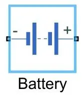
- The Battery block represents a simple battery model.
- This block has four modeling variants which are:
- Uninstrumented | No thermal port:
- The basic model does not output battery charge level or simulates thermal effects and also this modeling variant is the default.
- Uninstrumented | Show thermal port:
- The model with an exposed thermal port and also this model does not measure the internal charge level of the battery.
- Instrumented | No thermal port:
- The model with an exposed charge output port and also this model does not simulate thermal effects.
- Instrumented | Show thermal port:
- The model lets you measure the internal charge level of the battery and simulate thermal effects with both the thermal port and the charge output port are exposed.
- Uninstrumented | No thermal port:
- This Battery block represents the energy source for the electric vehicle.
- If by selecting Infinite for the battery charge capacity parameters, the block models the battery as a series internal resistance and a constant voltage source.
- If by selecting Finite for the Battery charge capacity parameter, the block models the battery as a series internal resistance plus a charge dependent voltage source will be defined by
- `V=(V_(nom)*SOC)/(1-beta*(1-SOC)`
- DC MOTOR:
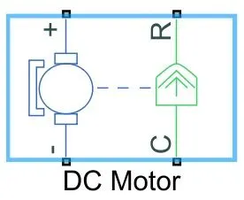
- The DC Motor block represents the electrical and torque characteristics of a DC motor.
- This DC motor block assumes that no electromagnetic energy is lost, and hence the back-emf and torque constants have the same numerical value when in SI units. Motor parameters can either be specified directly or derived from the no-load speed and small torque. If no information is available on the armature, Inductance, these parameters can be set to some small non-Zero values.
- When a positive current flows from the electrical + to - ports, a positive torque acts from the mechanical C to R ports. Motor torque can be changed by altering the sign of the back-emf or torque constants.
- VEHICLE MODELING:
- TIRE:
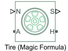
- This Tire block Represents the longitudinal behavior of a highway Tire characterized by the tire Magic Formula. The block is built from Tire-Road Interaction (Magic Formula) and Simscape Foundation Library Wheel and Axle blocks. Optionally, the effects of tire inertia, stiffness, and damping can be included.
- Connection A is the mechanical rotational conserving port for the wheel axle.
- Connection H is the mechanical translational conserving port for the wheel hub through which the thrust developed by the tire is applied to the vehicle.
- Connection N is a physical signal input port that applies the normal force acting on the tire. The force is considered positive if it acts downwards.
- Connection S is a physical signal output port that reports the tire slip.
- Optionally physical signal port M by setting Parameterize by to Physical signal Magic Formula coefficients. Physical signal port M accepts a four-element vector corresponding to the B, C, D, and E Magic Formula coefficients.
- This Tire block Represents the longitudinal behavior of a highway Tire characterized by the tire Magic Formula. The block is built from Tire-Road Interaction (Magic Formula) and Simscape Foundation Library Wheel and Axle blocks. Optionally, the effects of tire inertia, stiffness, and damping can be included.
- SIMPLE GEAR:
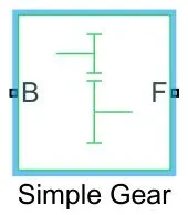
- This block represents a fixed-ratio gear or gearbox. No inertia or compliance is modeled in this block. You can optionally include gear meshing and viscous bearing losses.
- Connections B (base) and F (follower) are mechanical rotational conserving ports.
- Specify the relation between base and follower rotation directions with the Output shaft rotates parameter. Optionally thermal effects include and expose thermal conserving port H by right-clicking on the block and selecting Simscape block choices to switch between variants
- VEHICLE BODY:
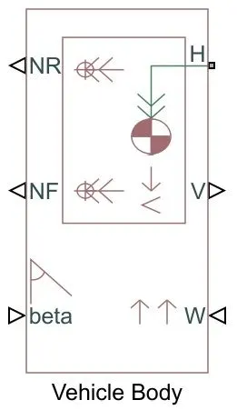
- This block represents a two-axle vehicle body in longitudinal motion. The block accounts for Body mass, Aerodynamic drag, Road incline, and Weight distribution between axles due to acceleration and Road profile. The vehicle can have the same or a different number of wheels on each axle. Optionally pitch includes and suspension dynamics or additional variable mass and inertia.
- The vehicle does not move vertically relative to the ground.
- Connection H is the mechanical translational conserving port associated with the horizontal motion of the vehicle body. The resulting traction motion developed by tires should be connected to this port.
- Connections V are physical signal output ports for vehicle velocity
- Connections NF and NR are physical signal output ports for front and rear normal wheel forces, respectively.
- Connections W and beta are physical signal input ports corresponding to headwind speed and road inclination angle, respectively.
- Wheel forces are considered positive if acting downwards.
- If the variable mass is modeled, the physical signal input ports CG and M are exposed. CG accepts a two-element vector representing the x and y distance offsets from vehicle CG to additional load mass CG. M represents the additional mass.
- If both variable mass and pitch dynamics are included, the physical signal port J accepts the inertia of the additional mass about its own CG.
- TIRE:
MODEL DESIGN OF ELECTRIC VEHICLE:
- SIMULINK MODEL OF EV:
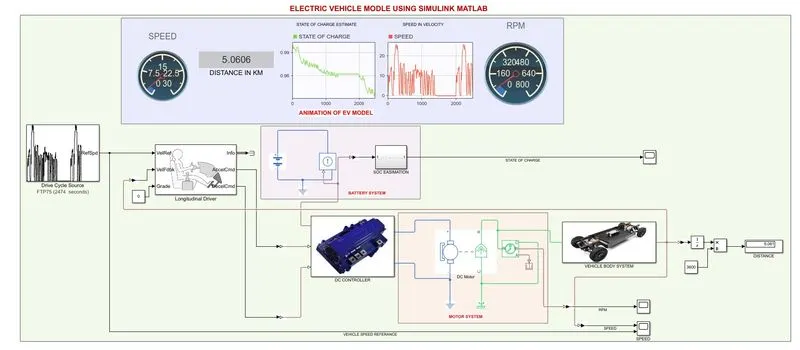
- Explanation:
- The Electric vehicle (EV) is constructed in a manner of FOUR step by step processes, So to design the EV model always starts within the order:
- Construction Of Vehicle Body Design.
- Construction Of Motor or Engine/ Selecting Of Motor or Engine.
- Suitable Control Unit For Motor or Engine.
- Source of Energy for Motor or Engine.
- Let's start with step-1: Construction Of Vehicle Body Design.
- The construction of vehicle body design mainly depends upon The vehicle Body block, Tire block, Simple Gear block, DC Motor (Mechanical Rotar side) block, and Longitudinal Driver block
- Tire connection to vehicle body:
- Basically, a car has four wheels. It is constructed in a way of Two wheels at the Front side and Two wheels at the Rare side
- Each Tire consists of an H-port which is a wheel Hub, A-port which is a wheel Axle, and N-port which is a Normal force.
- The Tire 1 & Tire 2 are Front Tire systems and The Tire 3 & Tire 4 are Rare Tire system
- The Front Tire system
- From Tire 1 block and Tire 2 block, the ports of Wheel Axle A1 are connected to Wheel Axle A2, and this intersection point is connected to the Follower(F) from Simple Gear.
- From Tire 1 block and Tire 2 block, the port of Wheel Hub H1 is connected to Wheel Hub H2, and this intersection point is connected to the Hub (H) of the Vehicle Body.
- From Tire 1 block and Tire 2 block, The port of Normal Force N1 is connected to Normal Force N2, and this intersection point is connected to Normal Front Force (NF) of the Vehicle Body.
- From Tire 1 block and Tire 2 block, The Slip of the Tire is Neglected.
- The Rare Tire system
- From Tire 3 block and Tire 4 block, the ports of Wheel Axle A3 are connected to Wheel Axle A4.
- From Tire 3 block and Tire 4 block, the port of Wheel Hub H3 is connected to Wheel Hub H4, and this intersection point is connected to the Hub (H) of the Vehicle Body
- From Tire 3 block and Tire 4 block, The port of Normal Force N3 is connected to Normal Force N4, and this intersection point is connected to Normal Rare Force (NR) of the Vehicle Body
- From Tire 3 block and Tire 4 block, The Slip of the Tire is Neglected
- Vehicle Body connection to Longitudinal Driver:
- The Vehicle Body Velocity (V) is connected directly Feedback to The Longitudinal Vehicle Velocity (VelFdbk)
- step-2: Construction Of Motor / Selecting Of Motor.
- Selecting of Motor is taken as DC Motor:
- The Motor system mainly depends upon DC Motor, Ideal Rotational Motion Sensor, H-Bridge controller, and Current Sensor
- The DC MOTOR is connected to Ideal Rotational Motion Sensor to find the RPM of the vehicle's speed.
- The DC Motor has Two systems:
- Electrical system:
- The Electrical system has two ports, a Positive (+) port and a Negative (-) Port
- The DC Motor Positive(+) port is connected to the Current Sensor of Negative(-) port
- The DC Motor Negative(-) port is connected to H-Bridge Negative(-) port and these two signals ports are connected through the Electrical Reference
- Mechanical System:
- The Mechanical system has two ports, Motor Caseing (C) port and Motor Rotor (R) Port
- The DC Motor of Motor Caseing (C) port is connected to the Motor Caseing (C) port of Ideal Rotational Motion Sensor and these two signals ports are connected through Mechanical Rotational Reference
- The DC Motor of Motor Rotor (R) port is connected to the Motor Rotor (R) port of Ideal Rotational Motion Sensor and this intersection point is connected to the Base (B) port Of the Simple Gear.
- Electrical system:
- step-3: Suitable Control Unit For Motor
- The Suitable Control Unit For Motor mainly consists of an H-Bridge controller, Controlled PWM Voltage, Controlled Voltage Source, Longitudinal Driver, and Driving Cycle Source
- H-Bridge Controller To DC Motor:
- The DC Motor Positive(+) port is connected to the Current Sensor of Negative(-) port and the Current Sensor of Positive (+) port is connected to the Positive(+) port of the H-Bridge
- The DC Motor Negative(-) port is connected to H-Bridge Negative(-) port and these two signals ports are connected through the Electrical Reference.
- H-bridge Motor drive To Controlled PWM Voltage:
- H-Bridge drive has PWM port, REF port which is ZERO VOLT REFERENCE, REV port which is REVERSE, and BRK port which is BREAKING
- Controlled PWM Voltage has PWM port, REF port which is ZERO VOLT REFERENCE, (ref+) port is Positive Terminal, and (ref-) port is Negative Terminal
- Connections OF H-Bridge and Controlled PWM Voltage
- The H-Bridge PWM port is connected directly to the PWM port of the Controlled PWM Voltage
- The H-Bridge REF port is connected directly to the REF port of the Controlled PWM Voltage and there is an interconnection between the REV port of the H-Bridge.
- The H-Bridge REV port is connected to Solver Configuration and Electrical Reference
- The H-Bridge BRK port is connected to the Positive (+) port of the controller voltage Source 1 and the controller voltage Source 1 of the Negative(-) port is connected to the Electrical Reference Junction point.
- The Controlled PWM Voltage ref+ port is connected to the Controlled Voltage Source Positive(+) and Negative (-) port of the Controlled PWM Voltage connected to the ref- port of the Controlled PWM Voltage and interconnection through the Electrical Reference Junction point.
- Longitudinal Driver Command Connected to Controlled Voltage sources:
- Longitudinal Driver Consists of VelRef port which is Vehicle Reference, VelFbdk port which is Vehicle Feedback Reference, Grade port which is Gradiante percentage, AccelCmd port which is Acceleration Command, and DecelCmd port which is Deceleration Command
- Acceleration Command:
- The AccelCmd port of the Longitudinal drive of the Physical system is connected to the Physical system of the Controlled Voltage source for the Acceleration Motion or Forward Movement of the vehicle.
- Deceleration Command:
- The DecelCmd port of the Longitudinal drive of the Physical system is connected to the Physical system of Controlled Voltage source-1 for the Breaking the Vehicle or Deceleration of the vehicle
- Acceleration Command:
- The Driving Cycle Source output velocity is directly connected to the VelRef port of Longitudinal Driver, which is Vehicle Reference Input source Velocity values
- Longitudinal Driver Consists of VelRef port which is Vehicle Reference, VelFbdk port which is Vehicle Feedback Reference, Grade port which is Gradiante percentage, AccelCmd port which is Acceleration Command, and DecelCmd port which is Deceleration Command
- H-Bridge Controller To DC Motor:
- The Suitable Control Unit For Motor mainly consists of an H-Bridge controller, Controlled PWM Voltage, Controlled Voltage Source, Longitudinal Driver, and Driving Cycle Source
- step-4: Source of Energy for Motor
- The Source of Energy for Motor is BATTERY Power supply of 300 volts
- The power supply is directly connected to DC Motor through Controlled Current Source and Current Sensor of the DC Motor
- In Battery System, It consists of Battery, Controlled current Source, and State Of Charge Estimation Calculation
- In the Battery system, The current is controlled through a Controlled current Source at which how much the amps flow in the Battery system
- The Value of Current Sensor (I) is Integrated to the value of Gain of `1/(80*3600)` is subtracted from 1
- The Electric vehicle (EV) is constructed in a manner of FOUR step by step processes, So to design the EV model always starts within the order:
- Explanation:
- SIMULINK MODEL OF DC CONTROLLER SUBSYSTEM:
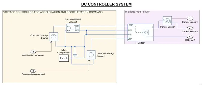
- Control Unit For DC Motor mainly consists of an H-Bridge controller, Controlled PWM Voltage, Controlled Voltage Source, Longitudinal Driver, and Driving Cycle Source
- H-Bridge Controller To DC Motor:
- The DC Motor Positive(+) port is connected to the Current Sensor of Negative(-) port and the Current Sensor of Positive (+) port is connected to the Positive(+) port of the H-Bridge
- The DC Motor Negative(-) port is connected to H-Bridge Negative(-) port and these two signals ports are connected through the Electrical Reference.
- H-bridge Motor drive To Controlled PWM Voltage:
- H-Bridge drive has PWM port, REF port which is ZERO VOLT REFERENCE, REV port which is REVERSE, and BRK port which is BREAKING
- Controlled PWM Voltage has PWM port, REF port which is ZERO VOLT REFERENCE, (ref+) port is Positive Terminal, and (ref-) port is Negative Terminal
- Connections OF H-Bridge and Controlled PWM Voltage
- The H-Bridge PWM port is connected directly to the PWM port of the Controlled PWM Voltage
- The H-Bridge REF port is connected directly to the REF port of the Controlled PWM Voltage and there is an interconnection between the REV port of the H-Bridge.
- The H-Bridge REV port is connected to Solver Configuration and Electrical Reference
- The H-Bridge BRK port is connected to the Positive (+) port of the controller voltage Source 1 and the controller voltage Source 1 of the Negative(-) port is connected to the Electrical Reference Junction point.
- The Controlled PWM Voltage ref+ port is connected to the Controlled Voltage Source Positive(+) and Negative (-) port of the Controlled PWM Voltage connected to the ref- port of the Controlled PWM Voltage and interconnection through the Electrical Reference Junction point.
- H-Bridge Controller To DC Motor:
- Control Unit For DC Motor mainly consists of an H-Bridge controller, Controlled PWM Voltage, Controlled Voltage Source, Longitudinal Driver, and Driving Cycle Source
- SIMULINK MODEL OF VEHICLE BODY SUBSYSTEM:
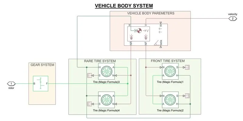
- The construction of vehicle body design mainly depends upon The vehicle Body block, Tire block, Simple Gear block, DC Motor (Mechanical Rotar side) block, and Longitudinal Driver block
- Tire connection to vehicle body:
- Basically, a car has four wheels. It is constructed in a way of Two wheels at the Front side and Two wheels at the Rare side
- Each Tire consists of an H-port which is a wheel Hub, A-port which is a wheel Axle, and N-port which is a Normal force.
- The Tire 1 & Tire 2 are Front Tire systems and The Tire 3 & Tire 4 are Rare Tire system
- The Front Tire system
- From Tire 1 block and Tire 2 block, the ports of Wheel Axle A1 are connected to Wheel Axle A2, and this intersection point is connected to the Follower(F) from Simple Gear.
- From Tire 1 block and Tire 2 block, the port of Wheel Hub H1 is connected to Wheel Hub H2, and this intersection point is connected to the Hub (H) of the Vehicle Body.
- From Tire 1 block and Tire 2 block, The port of Normal Force N1 is connected to Normal Force N2, and this intersection point is connected to Normal Front Force (NF) of the Vehicle Body.
- From Tire 1 block and Tire 2 block, The Slip of the Tire is Neglected.
- The Rare Tire system
- From Tire 3 block and Tire 4 block, the ports of Wheel Axle A3 are connected to Wheel Axle A4.
- From Tire 3 block and Tire 4 block, the port of Wheel Hub H3 is connected to Wheel Hub H4, and this intersection point is connected to the Hub (H) of the Vehicle Body
- From Tire 3 block and Tire 4 block, The port of Normal Force N3 is connected to Normal Force N4, and this intersection point is connected to Normal Rare Force (NR) of the Vehicle Body
- From Tire 3 block and Tire 4 block, The Slip of the Tire is Neglected
- Vehicle Body connection to Longitudinal Driver:
- The Vehicle Body Velocity (V) is connected directly Feedback to The Longitudinal Vehicle Velocity (VelFdbk)
- The Simple Gear Port B (base) is connected to the DC Motor port of Mechanical Rotor (R)
- SIMULINK MODEL OF STATE OF CHARGE ESTIMATION SUBSYSTEM:
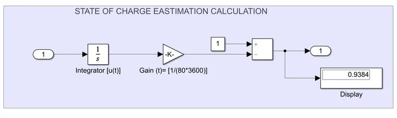
- In Battery System, It consists of Battery, Controlled current Source, and State Of Charge Estimation Calculation
- In the Battery system, The current is controlled through a Controlled current Source at which how much the amps flow in the Battery system
- The Value of Current Sensor (I) is Integrated to the value of Gain of `1/(80*3600)` is subtracted from 1
- where 80 is amps, 3600 is time (t)
- The SOC Calculated by `SOC=[(int(1/(amp*t)))-1]`
- DISTANCE CALCULATION:
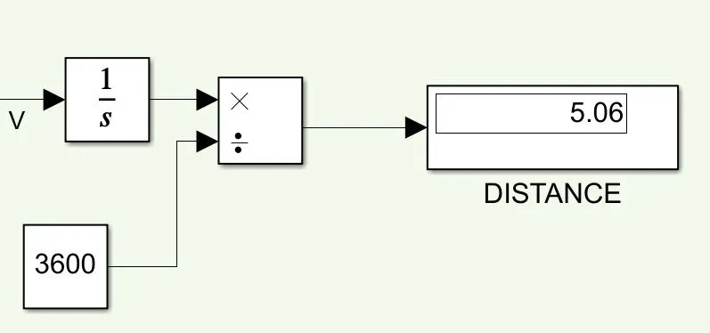
- To calculate the distance of the vehicle, we know that the Integration of velocity is Displacement or Distance and by divided with 3600 seconds gives Distance in Km/s
- Here The Total distance Of the Electric Vehicle is Travel around 5.06 km/s
MODEL PARAMETERS FOR ALL THE COMPONENTS:
- DRIVING CYCLE:
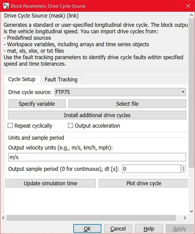
- The driving cycle source block generates the standard plot at which the vehicle can accelerate and decelerate for a time period. Here the FTP75 driving cycle is chosen.
- The output velocity units are taken as a meter per second.
- In the driving cycle source there plenty of plots can be chosen. The driving cycle source acts as a different output velocity source with (n) number of accelerating and decelerating in a graph.
- The term decelerating is acts as the breaking of the vehicle or slowdown of the vehicle.
- The parameters for this block are in-build data. No changes in the parameters for the driving cycle source.
- Now The output of the driving cycle source is connected to Longitudinal Driver.
- LONGITUDINAL DRIVER:
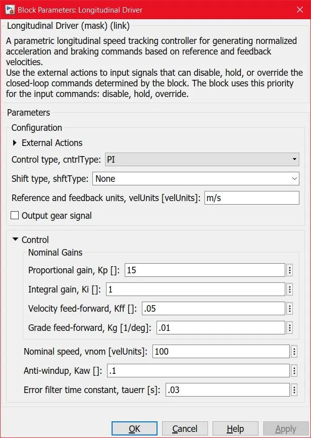
- The Longitudinal Driver block parameters consist of configuration and control.
- In Configuration setting It has External Actions in that Control Type, Shift Type, and Reference and Feedback units
- Now Control Type Parameters are set to PI (Proportional-Integral), and Shift Type to None, and Reference and Feedback units to m/s
- Now Control has Nominal Gains under this Proportional Gain, Integral gain, velocity feed-forward, and grade feed-forward.
- It also has Nominal speed, Anit-windup, and Error filter time constant.
- Now a subset of Control is going to be at Default Settings
- CONTROLLER:
- H-BRIDGE CONTROLLER:
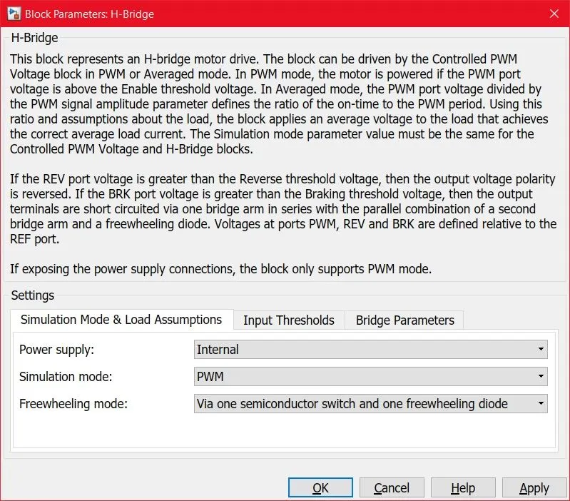
- The H-Bridge controller has three types of parameters which are simulation Mode & Load Assumptions, Input Thresholds, and Bridge Parameters.
- Now In Simulation Mode & Load Thresholds, It has a Power supply, Simulation mode, and Freewheeling mode.
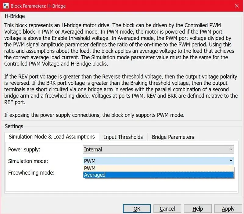
- Now In Simulation Mode & Load Thresholds:
- The Power supply is set Internal
- Simulation mode is set to Averaged from PWM
- Freewheeling mode is set to Via one semiconductor switch and one freewheeling diode.
- Now In Simulation Mode & Load Thresholds:
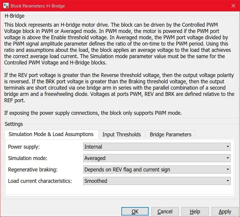
- Now In Simulation Mode & Load Thresholds
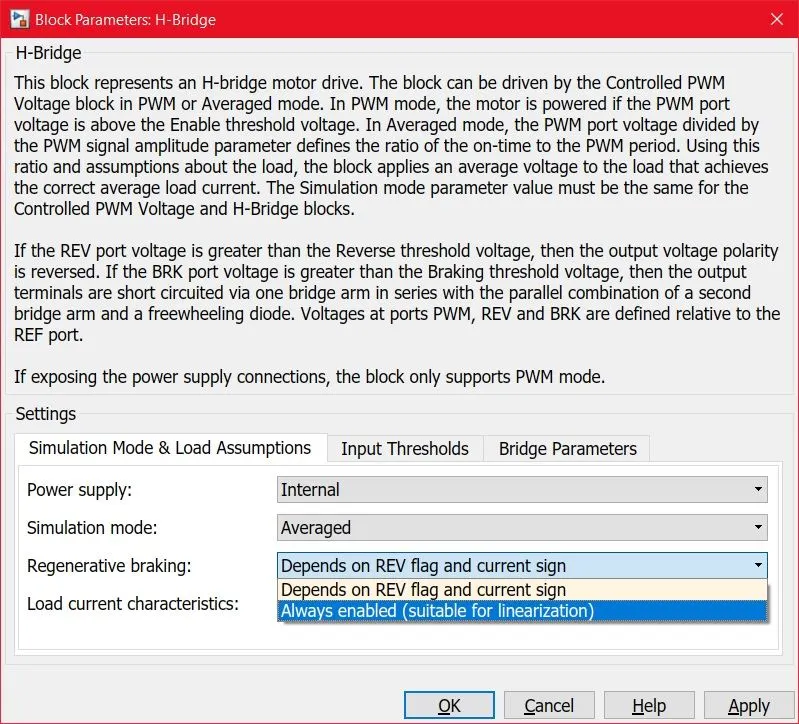
- When The Simulation mode is set to Averaged, Two different modes will popups which are:
- Regenerative braking
- Load current characteristics
- When The Simulation mode is set to Averaged, Two different modes will popups which are:
- Now In Simulation Mode & Load Thresholds
- Now In Simulation Mode & Load Thresholds
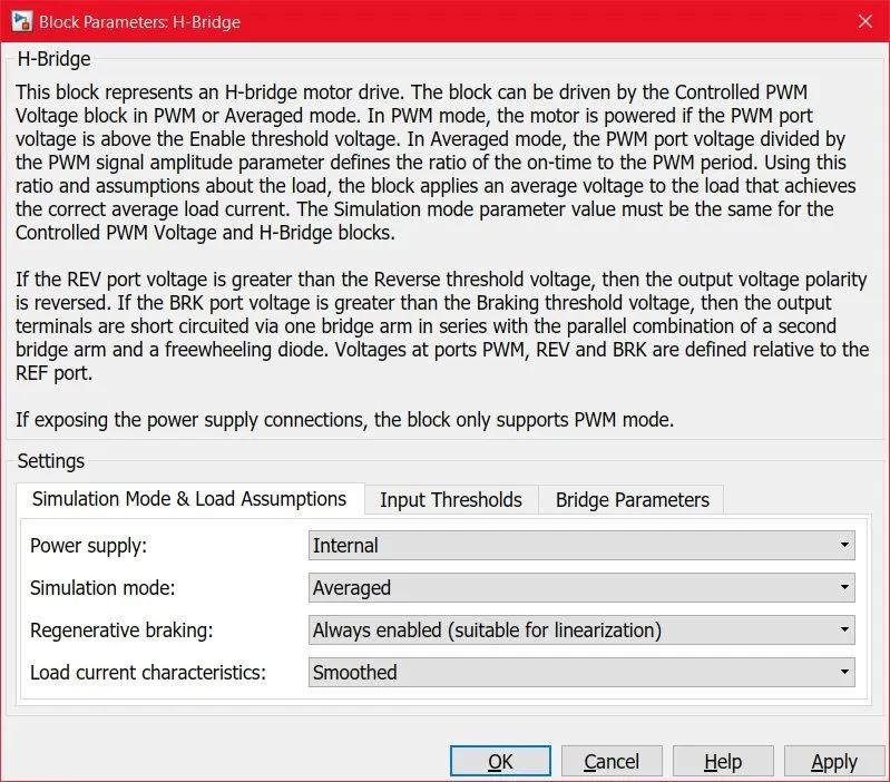
- Now Regenerative breaking is set to Always enable. which means Regenerative breaking is present in this model
- Now In Simulation Mode & Load Thresholds
- Now In Simulation Mode & Load Thresholds
- Load current characteristics are set to Smoothed
- Now In Simulation Mode & Load Thresholds
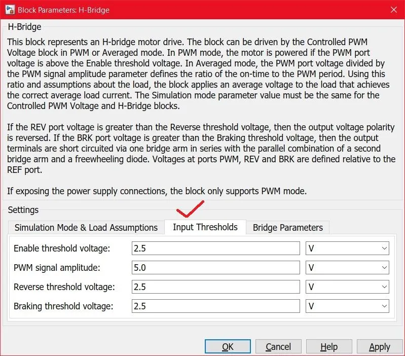
- Now Input Thresholds are set to default parameters. This consists of Enable threshold voltage, PWM signal amplitude, Reverse threshold voltage, and Breaking threshold voltage.
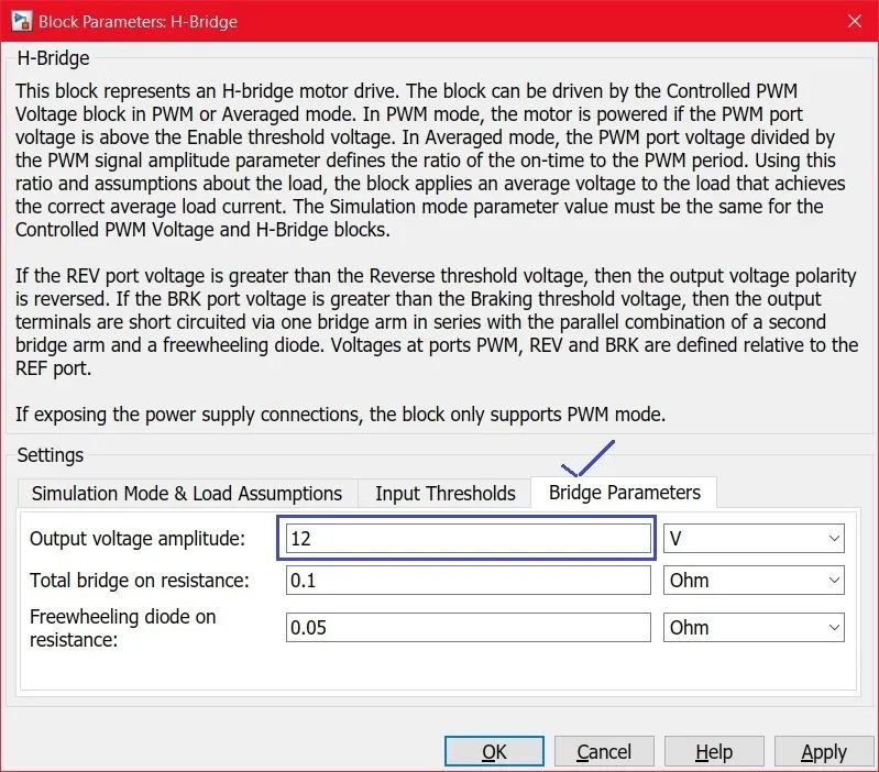
- Now Bridge Parameters consists of:
- output voltage amplitude
- Total bridge on resistance and Freewheeling diode on-resistance are default parameters
- Now Bridge Parameters consists of:
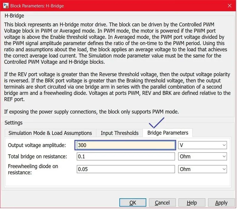
- Now In Bridge Parameters
- output voltage amplitude is set to 300 volts. Because the Input Voltage source is 300 volts.
- Now In Bridge Parameters
- H-BRIDGE CONTROLLER:
- CONTROLLED PWM VOLTAGE:
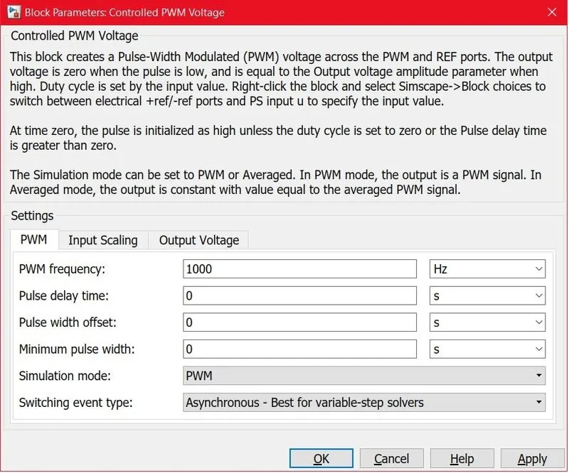
- The controlled PWM voltage parameters have PWM, Input Scaling, and Output Voltage
- In PWM it consists of:
- PWM frequency
- Pulse delay time
- Pulse width offset
- Minimum pulse width
- Simulation mode
- Switching event type.
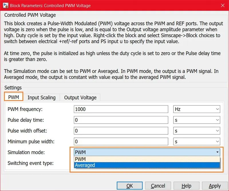
- In PWM, when Simulation mode is set Averaged from PWM settings it converts to
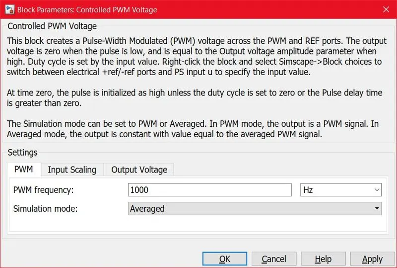
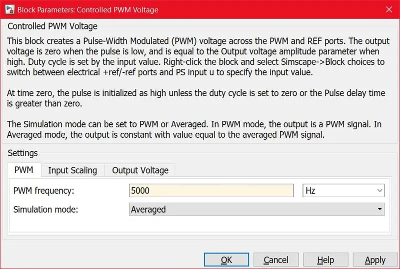
- In PWM, when Simulation mode is set Averaged. It eliminates all other settings to run a smooth simulation. It has only PWM frequency and it is set to a default of 1000 `H_z`
- Now in PWM
- PWM frequency is set to 5000`H_z` for better Pulse
- Now in PWM
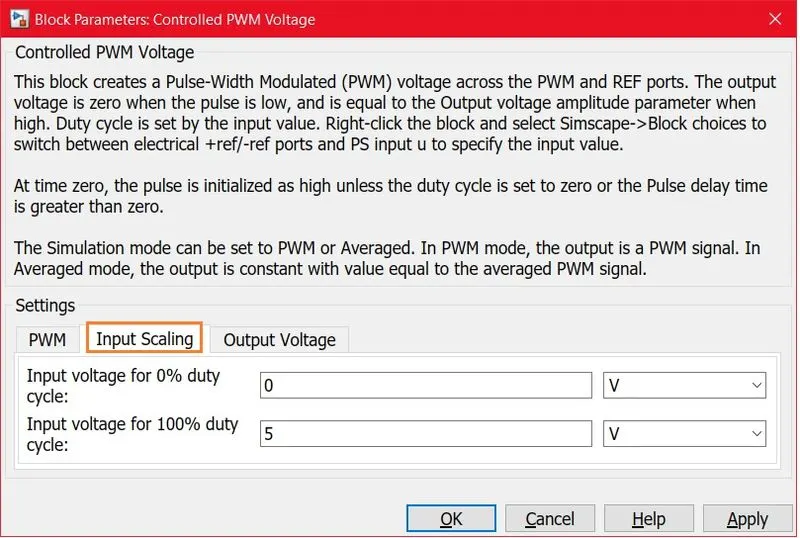
- In Input Scaling the above values are set to default parameters
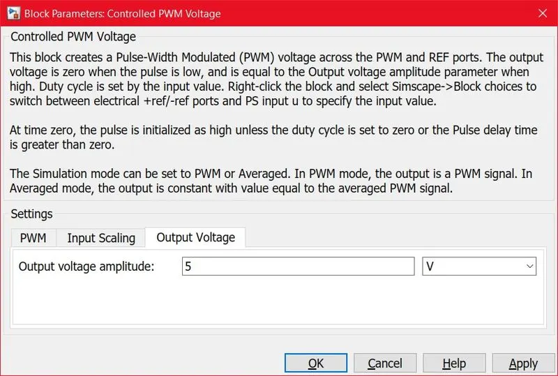
- In Output voltage, it has Output voltage amplitude which is set to 5 volts as default
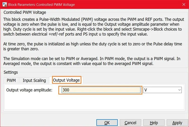
- Now Output voltage amplitude is set to 300 volts because the Input voltage source is 300 volts
- BATTERY:
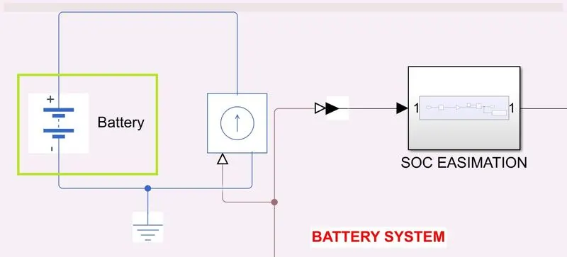
- In Battery System, It consists of Battery, Controlled current Source, and State Of Charge Estimation Calculation
- In the Battery system, The current is controlled through a Controlled current Source at which how much the amps flow in the Battery system
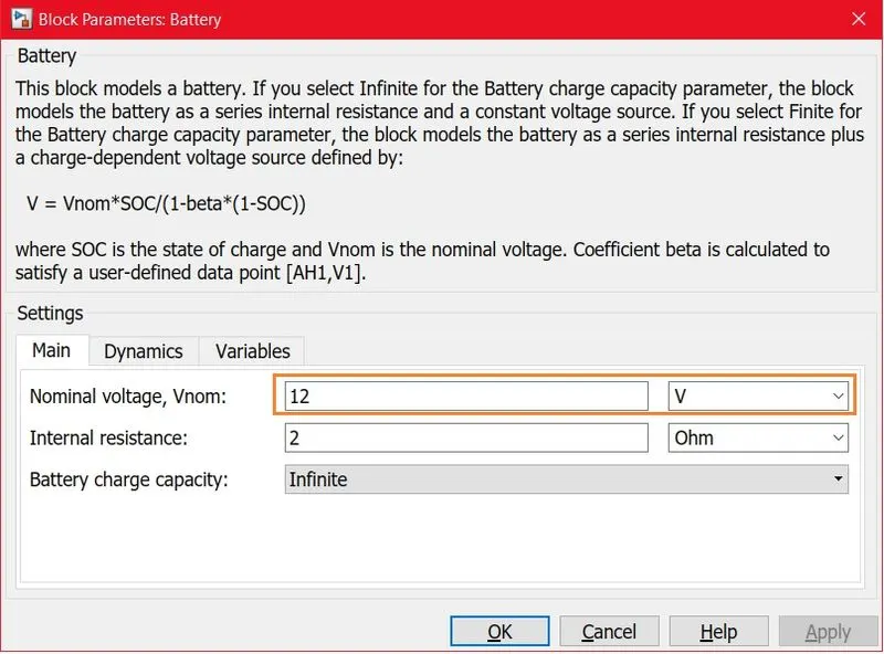
- The Battery consists of Main, Dynamic, and Variables
- The Dynamic conditions are OFF and Variables are at Default conditions
- In battery it's Initially the Nominal Voltage is set to 12 volts
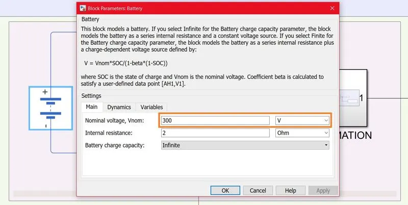
- In Battery, The Nominal voltage is set to 300 volts
- DC MOTOR:
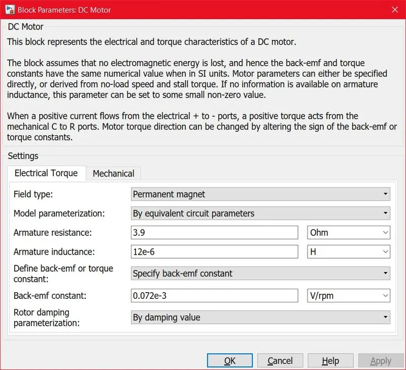
- The DC motor Represents Electrical Torque and Mechanical Parameters
- In Electrical Torque it consists of
- Field Type
- Model parameterization
- Armature resistance
- Amature Inductance
- Define back-emf to torque constant
- BAck-emf constants
- Rotor damping Parameterization
- These parameters are in default conditions when the block opens
- In Electrical Torque it consists of
- The DC motor Represents Electrical Torque and Mechanical Parameters
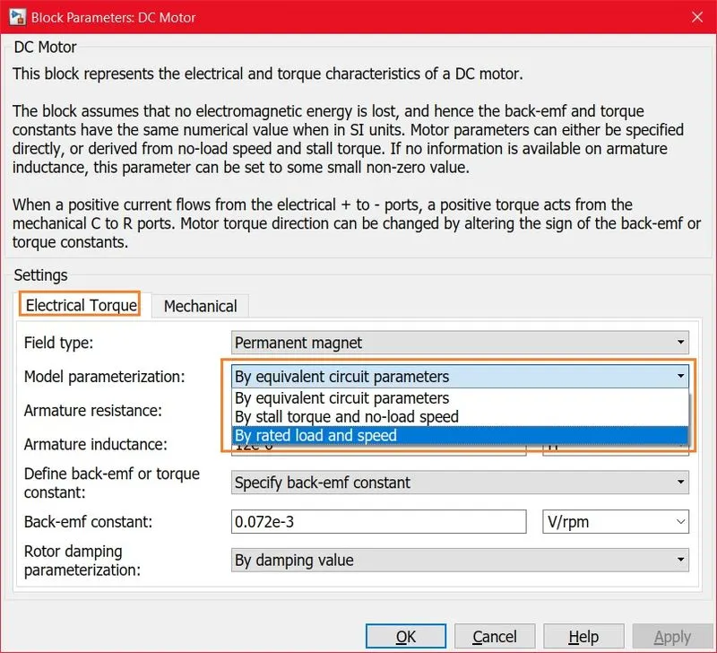
- In Electrical Torque
- When the Model Parameterization is set to By rated load speed from By equivalent circuit parameters it changes to complete different sets
- In Electrical Torque
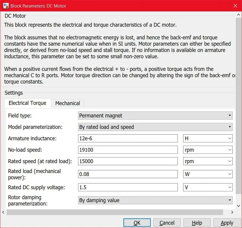
- In Electrical Torque
- When the Model Parameterization is set to By rated load speed
- It removes Armature resistance, Define back-emf or torque constant, and Back-emf constant
- It adds No-load speed, Rated speed (at rated load), Rated speed (mechanical power), and Rated DC supply voltage
- Which are at its default conditions values
- When the Model Parameterization is set to By rated load speed
- In Electrical Torque
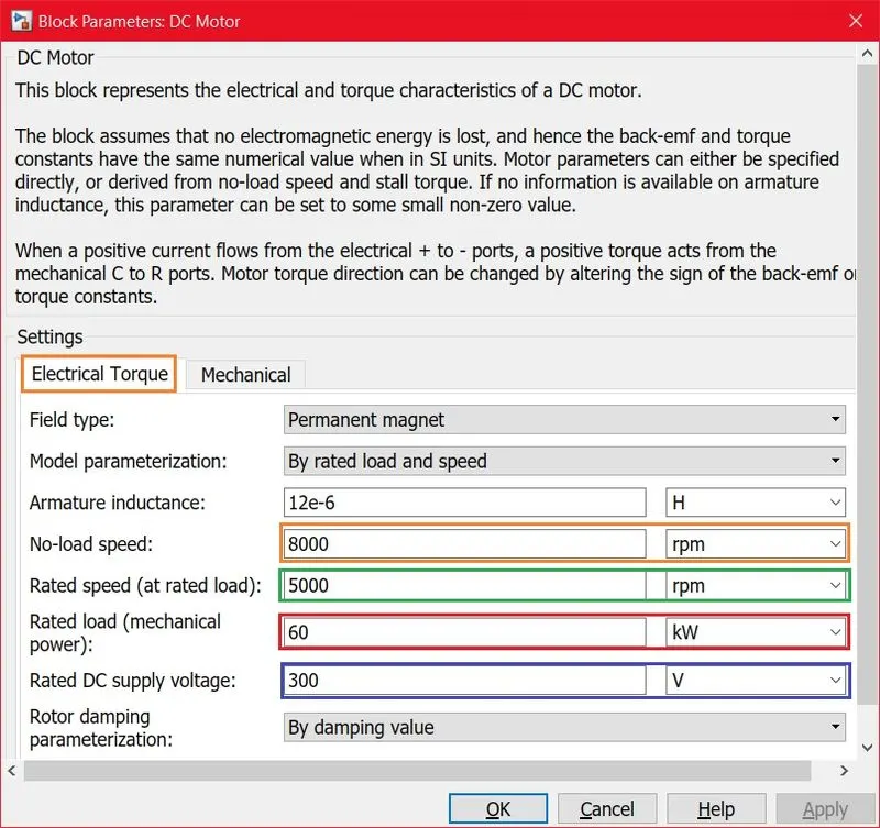
- In Electrical Torque
- When the Model Parameterization is set to By rated load speed
- No-load speed is set to 8000 rpm
- Rated speed (at rated load) is set to 5000 rpm
- Rated speed (mechanical power) is set to 60 KW
- Rated DC supply voltage is set to 300 volts
- When the Model Parameterization is set to By rated load speed
- In Electrical Torque
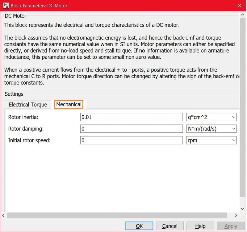
- The DC motor Mechanical parameters are set to the default condition without changes from the popup folder menu.
- It has Rotor inertia, Rotor damping, and Inertia rotor speed.
- The DC motor Mechanical parameters are set to the default condition without changes from the popup folder menu.
- VEHICLE MODELING:
- TIRE:
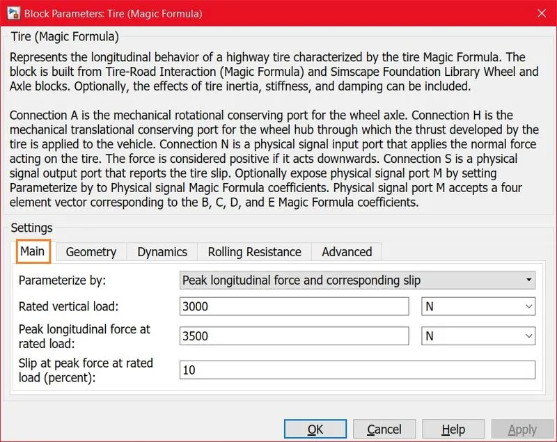
- The Tire helps the vehicle to move Forward and Backward with certain conditions to the parameters
- The Tire consists of Main, Geometry, Dynamics, Rolling Resistance, and Advance
- The Tire, the Main parameter is set to default condition values with without change in parameters
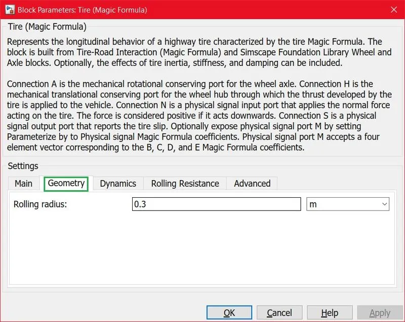
- The Rolling radius is set to 0.3 meters
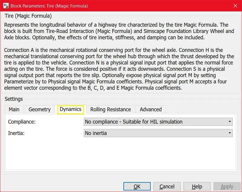
- Inertia is neglected
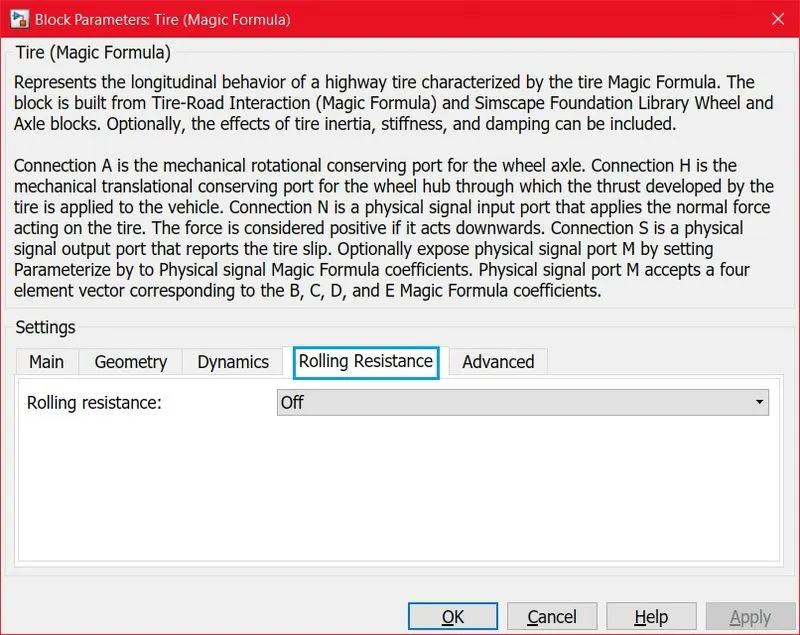
- No rolling resistance is present in this model parameters
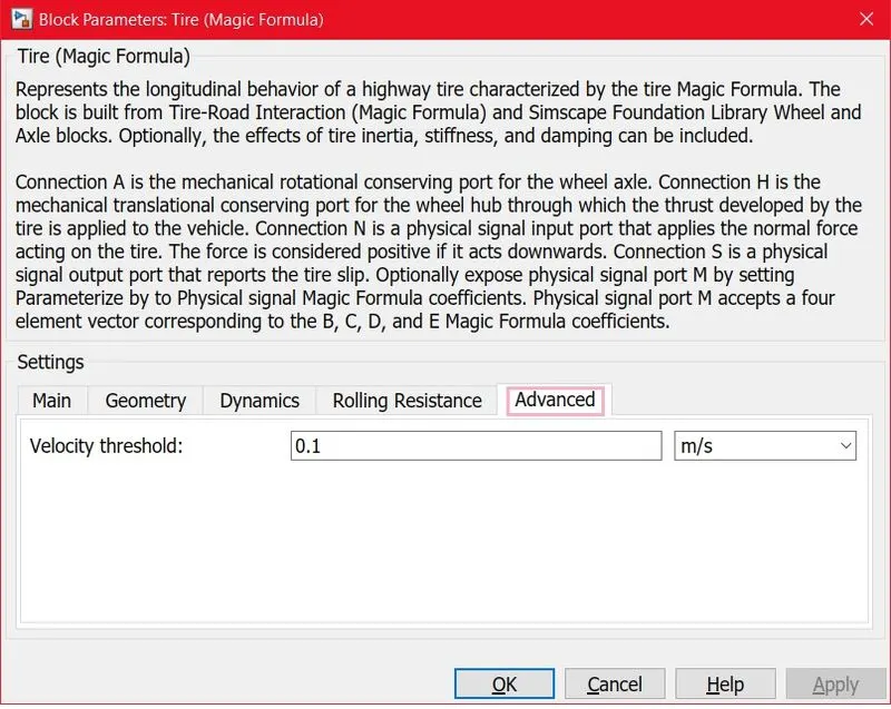
- The velocity threshold is set to 0.1 m/s
- SIMPLE GEAR:
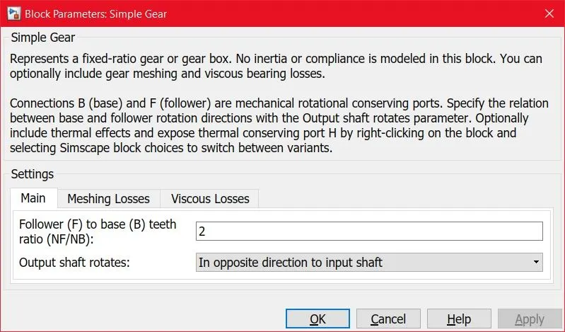
- The Simple Gear is consists of Main parameters, Meshing Losses, and Viscous Losses
- The main parameters consist of
- Follower(F) to Base (B) teeth ratio is initially set to 2
- Output shaft rotates
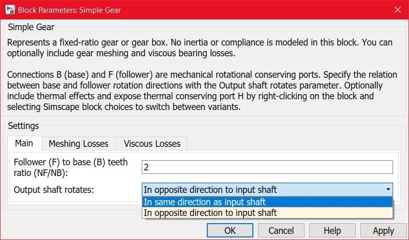
- Now the Output Shaft Rotates set to In the same direction to an input shaft
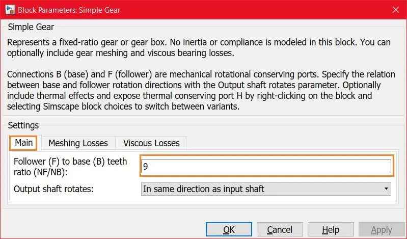
- Follower(F) to Base (B) teeth ratio is set to 9
- VEHICLE BODY:
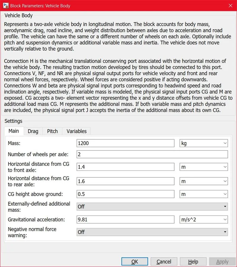
- The vehicle body parameters are consists of Main, Drag, Pitch, and Variables
- In Main Parameters
- Mass is set to 1200 Kg
- The number of wheels per axle is set to 2
- Gravitational Acceleration is set to 9.81 `m/s^2`
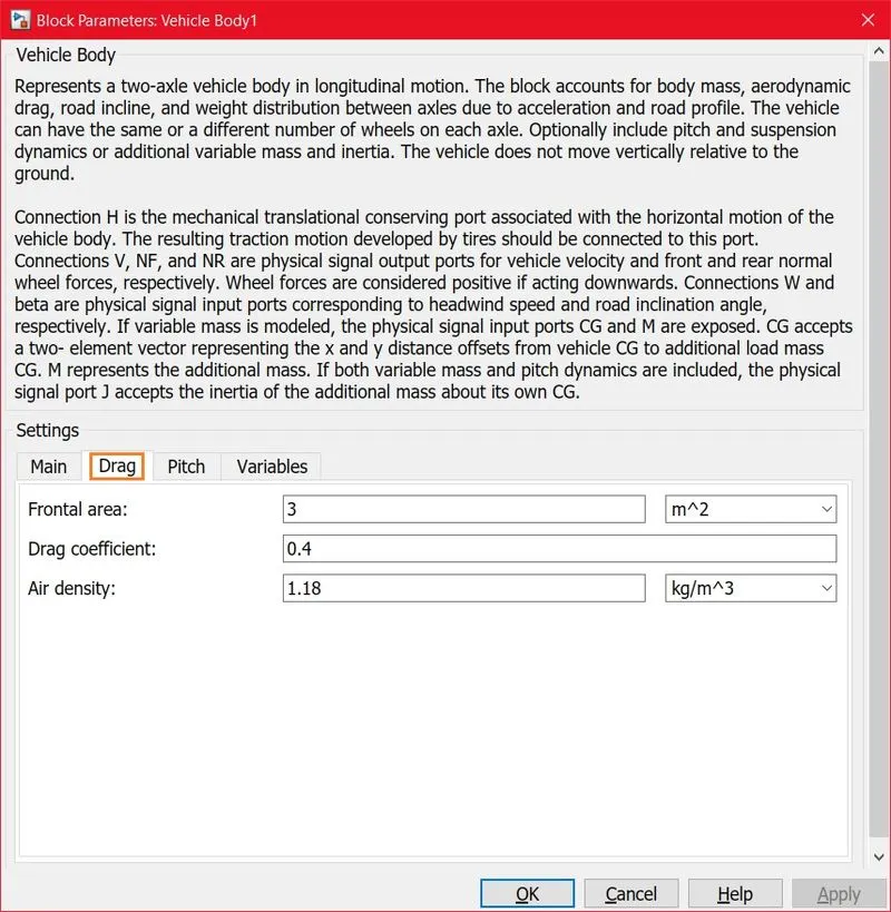
- In Drag parameters
- The frontal area is set to 3 `m^2`
- The Drag coefficient is set to 0.4
- Air density is set to 1.18 `k_g/m^3`
- In Drag parameters
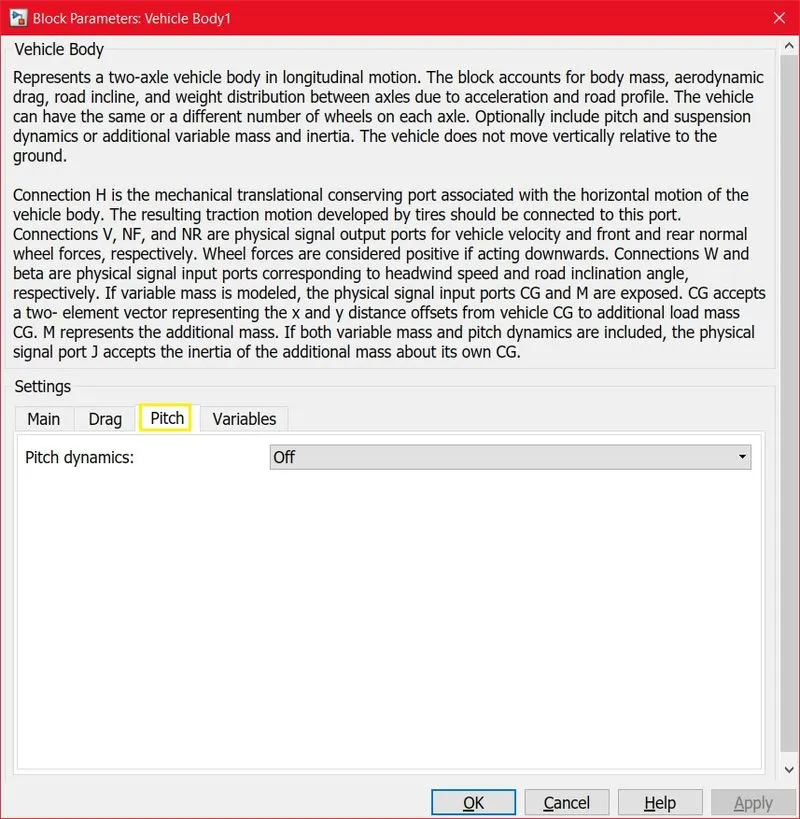
- The Pitch dynamic is neglected
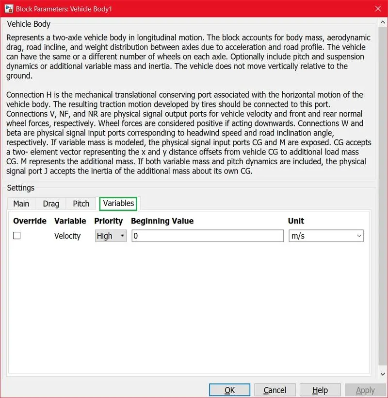
- Variables Velocity value Beginning from Zero and Priority is set to High.
- TIRE:
RESULTS:
- STATE OF CHARGE:
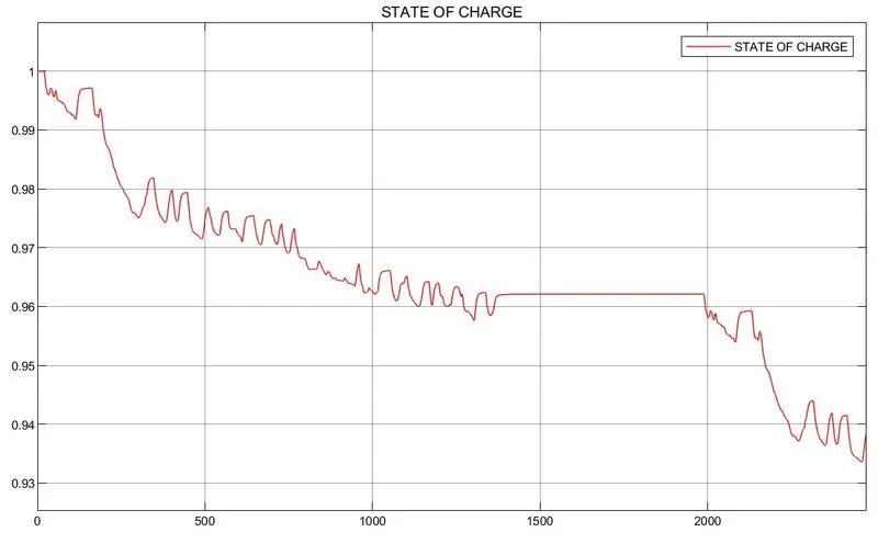
- This plot represents the State Of Charge Estimation in percentage. Here value 1 indicates 100% Fully Charged Battery and 0 indicates 0% Fully Drained Battery.
- Now from the Vehicle Speed is noted down from Driving Cycle Source at where the Vehicle Runs up to 2474 seconds for approximate 41.2 minutes, The battery dropped from 100% to 93.8%
- So the battery dropped 6.2% for 300 Volt Battery.
- VEHICLE SPEED DATA:
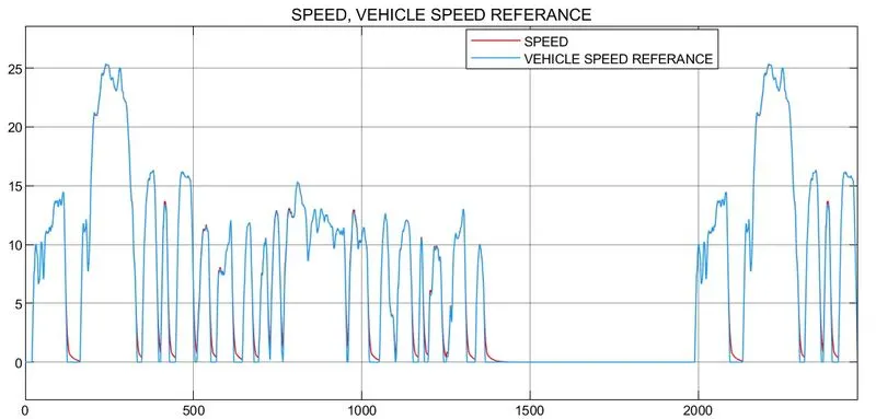
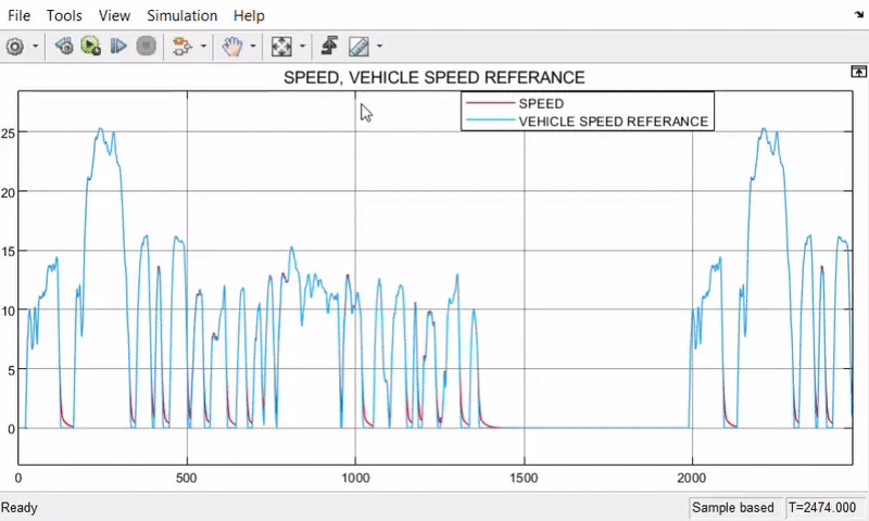
- The Driving Cycle Source of FTP75 is the Vehicle Speed Reference for the time period up to 2474 seconds
- The Orginal Speed Of the vehicle is trying to reach the accurate values of Vehicle Speed Reference
- The Maximum Speed Of the Vehicle reaches two times at 25 m/s
- VEHICLE RPM DATA:
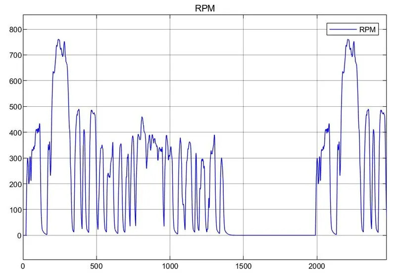
- The Vehicle RPM Data is Taken From Ideal Rotational Motion Sensor at which port (w) which is Angular Velocity in units rad/s
- The Maximum RPM reaches 761 rad/s
MODEL ANIMATION WORKING:
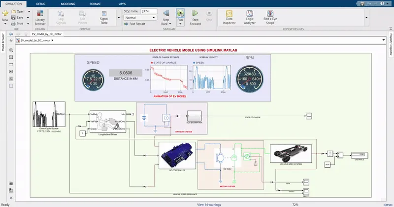
VEHICLE SPEED RESULT:
CONCLUSION:
- THE ELECTRICAL VEHICLE OF (EV) MODEL IS SUCCESSFULLY DESIGN THROUGH THE HELP OF MATLAB SIMULATION
- THE ELECTRICAL VEHICLE ACHIEVED THE TOTAL DISTANCE OF TRAVELED BY VEHICLE IS 5.06 KM/S. AT WHICH THE DRIVING CYCLE OF FTP75 SOURCE IT RUN FOR ABOUT 2474 SECONDS
- THE STATE OF CHARGE AT WHICH THE BATTERY OF 300 VOLTS OF MAXIMUM CHARGE IS DROPPED TO 93.8%, SO THE BATTERY IS DROPPED FROM 100% TO 93.8%.
REFERENCE LINK: