Final Project: Design of an Electric Vehicle
Project: Create a MATLAB model of electric car which uses a battery and a DC motor. Choose suitable blocks from Powertrain block set. Prepare a report about your model including following:
Objectives:
- System level configurations
- Model parameters
- Results
- Conclusion
Title: Design and Simulation of Electric vehicle using MATLAB
Objectives:
- System-level configurations
- Model parameters
- Results
- Conclusion
Introduction:
In recent days the transportation system is in transformation of fuels. Battery is one of the alternative energy source to run the vehicle. This project is about designing Electric vehicle using DC motor, Where the vehicle simulation is done using MATALAB Simulink R2020b.
To design the Electric vehicle, Matlab Power train block set is used.
System Level configurations of the Model:
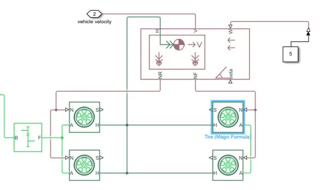
To design the Electric vehicle, the Vehicle body is simulated with 4 tires using Magic formula, Vehicle body.
To design the Electric vehicle, the Vehicle body is simulated with 4 tires using Magic formula, Vehicle body.
Battery with 12 V, DC Motor, FTP 75 Drive cycle, Longitudinal Driver, PWM controlled voltage source, H-bridge are the blocks selected from the power train block set.
Model Parameters:
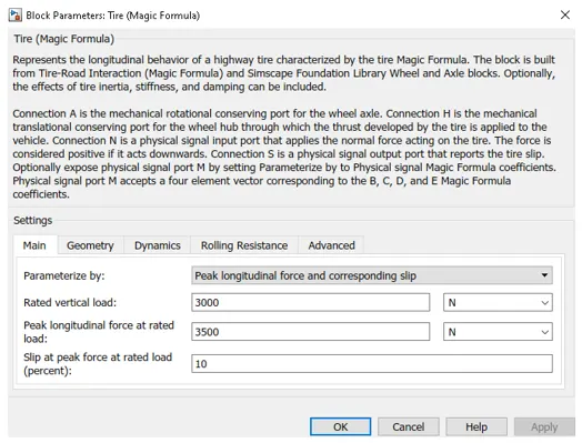
Tire:

The Tire (Magic Formula) block models a tire with longitudinal behavior given by the Magic Formula. The longitudinal direction of the tire is the same as its direction of motion as it rolls on pavement. This block is a structural component based on the Tire-Road Interaction (Magic Formula) block.
Tire Parameters:
Vehicle Body:
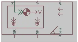
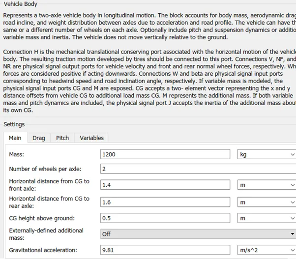
The Vehicle Body block represents a two-axle vehicle body in longitudinal motion. The vehicle can have the same or a different number of wheels on each axle. The block accounts for body mass, aerodynamic drag, road incline, and weight distribution between axles due to acceleration and road profile. The vehicle does not move vertically relative to the ground.
Vehicle Model and its simulation:
DC Motor Model and its simulation:
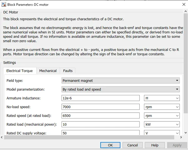
DC Motor:

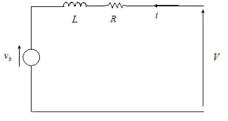
The DC Motor block represents the electrical and torque characteristics of a DC motor using the following equivalent circuit model:
H-Bridge:
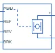
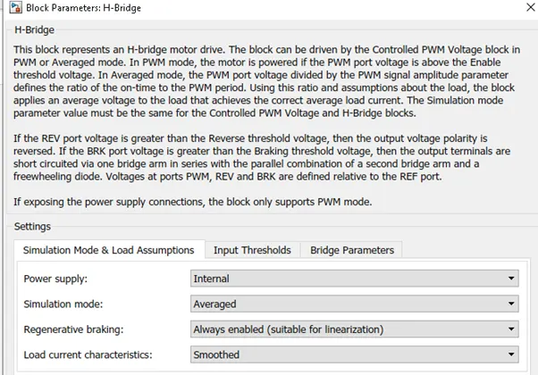
The H-Bridge block represents an H-bridge motor driver.
PWM voltage source:

The Controlled PWM Voltage block represents a pulse-width modulated (PWM) voltage source.
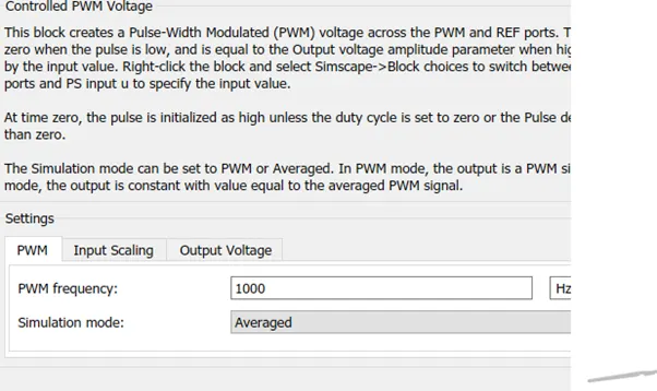
DC Motor is connected with H-bridge and H-bridge is connected with controlled PWM voltage.
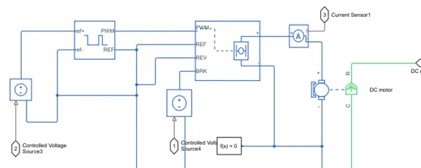
Controlled Pwm voltage is connected to the longitudinal driver block. which intern connected to the Drive cycle.
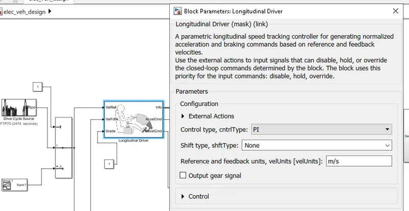
Drive cycle used:
Drive Cycle used is FTP75.
Overall Model of the Designed Electric vehicle:
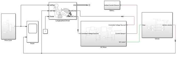
Results:
The Drive cycle chosen is FTP75 and below is the reference plot being used by FTP 75.
Fig: Drive cycle FTP75 (velocity Vs Time)
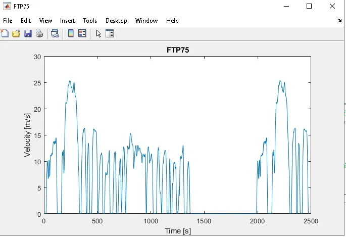
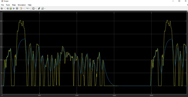
Fig: Scope result showing the comparison of Drive cycle reference and Vehicle velocity. (Yellow plot is the reference drive cycle and the Blue plot is the vehicle velocity which is fed to the longitudinal Driver.
Conclusion:
The vehicle is operating with a DC motor and battery as an energy source.
The conclusions made are that vehicle velocity is dependent on the vehicle reference speed.
Drive cycle shows the speed time characteristics. and the designed vehicle is showing a similar speed ratio with respect to the reference speed of the drive cycle.
While the speed-time curve shows immediate variation in speed from peak to zero, but the vehicle is decelerating with some delay. The same is happening with the acceleration of the vehicle.